Note : Les descriptions sont présentées dans la langue officielle dans laquelle elles ont été soumises.
CA 02486202 2004-11-22
Specification
The proposed method and air conditioning system were develop to solve the
problem of
purification, cooling and refreshing of the indoor air to eliminate root cause
of a "Sick
building syndrome" and create healthy conditions for people who live in large
cities, that
are affected by smog, such as Toronto and Hamilton in Canada, New York and
Buffalo in
the USA, Mexico City. The symptoms attributed to this syndrome include
headache,
nausea, shortness of breath, sinus congestion, and eye-nose-throat irritation.
The
invention can be used for improving of the indoor air in individual homes,
offices and
production facilities.
Traditional air conditioning cooling systems that are described in Canadian
patents
1,298,470; 1,086,499, 1,248807 and 1,248,807 and US patents 6,775,995;
6,796,140;
6,434,963; 6,282,913 and 6,796,375 include a compressor, a condensing unit, an
expansion valve and an evaporator. The compressor compresses gaseous
refrigerant
exiting the evaporator and discharges the high-pressure refrigerant to the
condensing unit.
The condensing unit operates as a heat exchanger enabling heat transfer from
the gaseous
refrigerant to a heat sink such as air or water. The refrigerant condenses
within the
condensing unit and a state change occurs from gas to liquid. The liquid
refrigerant exits
the condensing unit and flows to the evaporator through the expansion valve.
The
evaporator also operates as a heat exchanger enabling heat transfer from the
atmosphere
surrounding the evaporator to the liquid refrigerant. As the heat transfer
occurs, the
temperature of the refrigerant increases until a state change occurs from
liquid to gas. The
gas refrigerant is drawn into the suction side of the compressor and the
cooling cycle
continues. The condensing unit can be one of an air-cooled condensing unit or
a water-
cooled condensing unit. All these systems do not refresh indoor air and in
many cases
have caused so called "Sick building syndrome" which has resulted due to the
accumulation of harmful impurities in indoor air.
The air purification system for a central air conditioning unit per the US
patent 6,761,756
includes a pan assembly including a pan member having bottom and side walls,
and also
having plurality of ports being spaced about and being disposed through the
bottom wall
with the pan member being adapted to hold water and to be disposed in a duct
for a
central air conditioning system; and also includes a plurality of air intake
members being
disposed in the ports of the pan member; and further includes cap assemblies
including a
plurality of tubular cap members being spaced above and disposed about the air
intake
members. This purification system produces significant amount of water and
humidity.
CA 02486202 2004-11-22
2
Humidity results in multiplication and growing of different types of harmful
bacteria and
respiratory infections. As a result such air conditioning system must be
equipped with
humidifiers.
Moisture separators per the US 6,782,709 or W08000468 and collectors for the
liquid
phase of a working medium of an air conditioning system per the US patent
6,792,773
significantly reduce humidity of indoor air. However, all these systems have
two major
weaknesses. First of all, they do not refresh indoor air. Secondly, these
cooling systems
still remain a breading place for harmful bacteria.
The air conditioner per Canadian patent 1,312,553 comprises water-absorbing
polymers
that are included in the path of a refrigeration cycle to remove accumulated
water or
water vapor that inherently develops. This filter still results in
contamination of the
indoor air with water and harmful bacteria.
Filters and ultraviolet light emitting devises per the US patents 6,743,279;
6,790,265 and
6,707,044 have been used to remove bacteria from the indoor air. The air
filter device
includes a filter net and one or more ultraviolet light-emitting diodes (UV
LEDs). The
filter net is disposed at an air passageway of the exhaust device. The UV LED
is disposed
on the exhaust device and located at one side of the filter net to irradiate
UV light toward
the filter net, hence accomplishing filtering and sterilizing effects to air
passing through
the exhaust device and thus improving the quality of indoor air. All know
filters and UV
devises provide disinfections of indoor air. However, they do not refresh
indoor air.
Carbon dioxide, heavy hydrocarbons and other contaminants affect human health.
Most advanced method of air conditioning per Canadian Application 2,472,752 of
2004/07/08 comprises injecting of purified liquid or cooled to cryogenic
temperature
oxygen and nitrogen or mixture of these gases into the air passage of the air
conditioning
system. This method resolved refreshing problem, but direct injection of cold
mixture of
oxygen and nitrogen can result in precipitation of moisture in the air passage
close to
injection valves. Also, direct injection of fresh air does not resolve
purification of indoor
air problem.
We have found that most disadvantages of all known methods and air
conditioning
systems can be overcome by cooling of inflowing air to cryogenic temperature,
separation of frozen or liquefied contaminants from airflow, followed by
preheating of
outgoing air to required temperature that is produced by an air conditioning
system.
Method as above wherein cooling and purification of inflowing air is performed
by
injecting of refreshing mixture of oxygen and nitrogen or either of these
gases at
cryogenic temperature into airflow through a heat exchanger that is placed
inside the air
passage of an air conditioning system.
Other embodiment of the proposed method allows performing deep purification of
indoor
air by cooling it to cryogenic temperature with using a cryogenic generator
that is
connected to an air passage of an air conditioning system.
CA 02486202 2004-11-22
In order to execute the proposed method, an air conditioning system that
includes a
compressor, air passages, outlets and inlets, oxygen and nitrogen storage
units, regulating
valves, comprises also a heat exchange that is placed in the air passage and
connected by
one opening to a liquid nitrogen and oxygen storage units while second one is
provided
with a nozzle for injecting of cryogenic oxygen-nitrogen mixture into outgoing
air.
To improve efficiency of an air conditioning system during continues heavy-
duty cycle
last on is provide with a bypass that is equipped with a heat exchanger for
the continues
cooling and purification of indoor air during removal of contaminants from a
major air
passage.
To speed up defrosting and removal of contaminants an air conditioning system
can also
be provided with a heat, ultraviolet or high frequency radiator that is placed
near a heat
exchanger and connected to a power supply.
The proposed air conditioning system can be manufactured as fully autonomous
or as a
module that is connected to a standard air conditioning system.
To improve energy efficiency by using outdoor air for preheating of injected
gases a heat
exchanger or mixer can be mounted with partial interface with outdoor air.
To ensure uneven usage and simultaneous refilling of an oxygen and nitrogen
storage
units, last one is manufactured with capacity that is 3 - 3.5 times greater
than capacity of
an oxygen one.
Other embodiment of the proposed air conditioning system allows performing
deep
purification by cooling and liquefying of inflowing air with using a cryogenic
generator
that is connected to an air passage of an air conditioning system.
For small compartments an air conditioning system can comprise a heat
exchanger that is
connected by one opening through a regulation valves and mixer to an oxygen
and
nitrogen storage units, while other opening is provided with a pipe line that
is at least
partially located inside a compartment and equipped with a nozzle and pan that
is adapted
to hold and disposed water.
Common air consists of approximately 78% nitrogen, 21 % oxygen, 1 % argon,
small
amounts of carbon dioxide and other impurities and contaminants. In addition,
variable
amounts of water vapor is present in air depending upon humidity as well as
other
contaminants that are produced by natural processes and human activities.
Differences in
boiling points provide the basis for purification of the indoor air by cooling
it to
cryogenic temperature that is accompanied by condensation and freezing of
contaminants. For example, boiling temperature of oxygen is -183°C,
nitrogen is -196°C,
carbon dioxide sublime at temperature -78° C. Liquid temperature of
most common
hydrocarbons is above -82.5°C (CHa). It is also well know that most
airborne microbes,
bacteria, mold, spores and other living and mineral contaminants are
affiliated with water
CA 02486202 2004-11-22
4
and large hydrocarbon molecules. Therefore, full purification of outgoing air
can be done
by cooling of inflowing air inside an air conditioning system to cryogenic
temperature
followed by separation of liquid and solid contaminants. This method can
produce
chemically pure and fresh air without any traces of impurities.
In drawings which illustrate embodiments of the inventions, Figure 1 is the
air
conditioning system that produces cooling and purification of indoor air by
injecting of
mixture of oxygen and nitrogen at cryogenic temperature into outgoing air
through the
heat exchanger that is placed in the air passage, Figure 2 is the air
conditioning system
that comprises the cryogenic generator that is connected to the air passage of
the air
conditioning system, Figure 3 is the air conditioning system produces
refreshment and
cooling of indoor air by direct injection and purging a small compartment with
fresh
oxygen - nitrogen mixture .
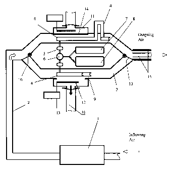
In the Figure 1, that illustrates the preferred embodiment, the compressor 1
is connected
by the air passage 2 to the cooling - purification module with the heat
exchangers 4. The
bypass 3 is connected to the main air passage 2. One opening of the heat
exchanger 4 is
connected through the regulation valves 5 and mixer 6 to the oxygen 7 and
nitrogen 8
storage units, such called small capacity Dewars or large capacity tanks for
bulk gases.
Other opening of the heat exchanger is provided with the nozzle 9. Hatches 10
on other
side of the bypass separate the bypass 3 and major air passage 2. The air
passage 2 and
bypass 3 are equipped with the defrosting section 11 for removing of moisture
and
contaminants. To speed up defrosting and ensure sterilization both defrosting
sections are
equipped with the heat, ultraviolet or high frequency radiators 12 that are
connected to
the power supplies 13. Both defrosting sections 11 are separated from the main
air
passage 2 and bypass 3 by hatches 14. The outgoing air passage area is
equipped with the
heater 15. All valves, ports and radiators are connected electronically to a
central control
board (which is not shown in the Figure 1 ). Each defrosting section 11 is
connected to the
duct 16 to enable removal of water and other contaminants during defrosting of
the heat
exchanger 4.
During working cycle the compressor 1 directs inflowing air throughout the air
passage 2
to the heat exchanger 4 whereby it is refreshed by injected mixture of oxygen
and
nitrogen. Heat exchange between injected gases and inflowing air takes place
on the outer
surfaces of the heat exchanger 4. As a result of this heat exchange, most
contaminants are
frozen or liquefied on the outer surface of the heat exchanger 4. Airborne
microbes and
bacteria, which are affiliated with moisture, are captured and hold by the
outer surface of
the heat exchanger 4 as well.
Environmental and temperature control is exercised by regulating of indoor air
flow rate
along the outer surface of the heat exchanger and flow rate of injected
mixture of cooled
to cryogenic temperature oxygen and nitrogen through the heat exchanger.
Outgoing air
also can be preheated to required temperature by the heater 15. After that air
is distributed
by the air conditioning system to compartments.
CA 02486202 2004-11-22
Purification of indoor air results in accumulation of significant amount of
contaminants
on the surfaces of the heat exchanger 4. To maintain high level of efficiency
of the air
conditioning system the hatch 8 is closed when it required redirecting
inflowing air into
the bypass 3 whereby purification, refreshing and cooling of outgoing air is
continued.
During this time the main air passage heat exchanger 4 is defrosted. The
defrosting
section 14 can be equipped with an infrared, ultraviolet or high frequency
radiator 14 to
speed up defrosting cycle. Water and other contaminants are disposed into the
duct 16
and removed from the air conditioning system. After that airflow is redirected
into the
major air passage again to perform defrosting of the bypass section.
Injecting of cryogenic mixture of oxygen and nitrogen can result in
overcooling of
outgoing air. To reduce overcooling and energy consumption partial preheating
of
injected mixture of oxygen and nitrogen can be performed by utilization of
energy of
outdoor air. For this purpose the mixer 8 can be mounted outside of the air
passage 2 or
the heat exchanger 4 can be partially protruded through the main air passage 2
to
interface with outdoor air. Both embodiments are illustrated in Figure 1
wherein the
protruded heat exchanger 4 is shown in the main air passage.
The described above embodiment can also produce enrichment of indoor air with
oxygen
from 20-21% in the beginning to 21.1-25% by the end of a workday by
proportional
changing flow rates of injected oxygen and nitrogen. It will significantly
reduce fatigue,
increase productivity and improve health conditions.
This embodiment can be assembled with using standard subassemblies and units.
For example, the liquid nitrogen and oxygen Dewars models 03-CL-160-C and 03-
CL-
240-C with capacity of 160 and 240 liters of liquid gases consequently can be
used for a
single home air conditioning system. These Dewars will produce approximately
344,000
liters of fresh purified air based on expansion ration of liquid oxygen to gas
as 1 to 860.
Fresh air supply and productivity of the proposed system depends on
consumption of
oxygen. For private homes it could be determined based on number of family
members.
Above-mentioned Dewars with liquid gases might be located outside of a home to
ensure
safety. Control of an air conditioning system can be done from a computer that
is placed
conveniently inside a home.
Standard tanks for storage of bulk gases with capacity of 1,000 - 25,000
liters can be
used for air conditioning systems for production facilities, schools,
hospitals and office
buildings.
The air conditioning system that is shown in Figure 2 illustrates another
embodiment that
produces purification and refreshing of indoor air with using the cryogenic
generator that
is connected to the air passage of the building with four floors wherein each
floor is
marked 17 through 20.
CA 02486202 2004-11-22
6
The air conditioning system comprises compressor 1 that directs inflowing air
into the
cryogenic generator 21. Outlet of the cryogenic generator 21 is connected to
the heating
section 15 whereby the outgoing air is preheated to required temperature. Each
floor is
equipped with the air inlet 22 for distribution of fresh purified air. Also
each floor is
equipped with outlets 23 of the exhaust passage 24 of the air conditioning
system. The
inflowing air passage 24 is equipped with the valve 25 to provide more outdoor
air into
the building to create excessive pressure inside compartments and compensate
oxygen
consumption. The cryogenic generator 21 is connected by the duct 16 to the
unit 26 for
collection of air contaminants. This unit is also equipped with the valve 27
that is used to
dispose contaminants. The compressor 1, cryogenic generator 21, heating
section 15, unit
26, valves 25 and 27 are connected electronically to the control board 28. The
air
conditioning system might be also equipped with the oxygen analyzers,
temperature
control units and other devises that execute temperature, moisture and
contamination
control to ensure proper function of the system.
During working cycle indoor air through the outlets 23 of the exhaust air
passage 24 is
directed by the compressor 1 into the cryogenic generator 21. The compressor
can be
provided also as a subassembly of the cryogenic generator 21. Indoor air is
cooled down
by the cryogenic generator 21. During cooling all contaminants are frozen or
liquefied
and separated from air. Solid or liquid contaminants are continuously or
periodically
disposed through the valve 27. Most contaminants can be extracted from air at -
90° C.
Therefore, to complete partial purification of indoor air cooling cycle can be
discontinued
and outgoing air can be redirected into the heating section 15. However, to
perform full
purification and produce air, which will comprise mixture of chemically pure
oxygen and
nitrogen, cooling cycle should be continued to reduce temperature of oxygen to
-183°C
and nitrogen to -196°C. After that liquid oxygen and nitrogen forwarded
into the mixer
wherein air with required concentration of oxygen and nitrogen is recreated
and directed
into the heating section I5.
This air conditioning system can be assembled with using the standard
equipment and
modules such as StirLIN-8 cryogenic generator or similar models, depending
upon
required productivity.
Direct injection of oxygen - nitrogen mixture into indoor air can simplify the
air
conditioning system for small compartments. Main features of such system are
shown in
Figure 3.
An air conditioning system shown if Figure 3 comprises a heat exchanger 4 that
is
connected by one opening through the regulation valves 5 and mixer 6 to the
oxygen 7
and nitrogen 8 storage units, while other opening is provided with the pipe
line 28 that is
at least partially located inside the compartment 17 and equipped with the
nozzle 9 and
pan 29 to hold and disposed water.
The heat exchanger 4 can be located outside to utilize energy of outdoor air
and preheat
oxygen-nitrogen mixture or inside the compartment 17. Injected mixtures of
oxygen and
CA 02486202 2004-11-22
7
nitrogen would refresh indoor air and cool it down to required temperature
while the pan
29 disposes water and other contaminants. This system can also produce partial
purification of indoor air, significant refreshment and required cooling to
create
comfortable and healthy conditions for example inside a recreation room.
The standard dosing systems such as NORHOF LN2 can be used for regulation of
oxygen and nitrogen flow rates in conjunction with LN Dewars with capacity
from 5 to
3 5 liters.
Fresh air supply and productivity of the proposed system depends upon
consumption of
oxygen.
Below is example of calculation of consumption of fresh air for family of
three persons:
It is well known that the average pair of human lungs can hold about 6 liters
of air, but
only small amount of it is used during normal breathing. 'The average-sized
(70 kg.) adult
mail has Tidal Volume (TV), or other word the amount of air breathed in or out
during
normal respiration, between 0.450 - 0.500 liter. At rest an average person
makes from 15
to I 8 breaths per minute. While breathing this person exchanging about 9
liters of air
thought his lungs. However, the human body consumes only 10% of this air, or
0.9 liter
per minute. Therefore, 1.2 liter of fresh air per minute is required to supply
the average
person with fresh air and remove carbon dioxide by purging. However, to
produce
significant refreshment effect, dilute and remove contaminants by purging
productivity of
this system must be 5 -10 times greater. Based on the foregoing productivity
of the
proposed system can vary from 6 to 12 liter per person per minute. Therefore,
two
Dewars with total capacity about 344,000 liters can provide average person
with fresh air
for 20 - 40 days or family of three persons for about 7 -14 days around a
clock.
Implementation of described above air conditioning method and systems will
eliminate
the root cause of "Sick building syndrome" and supply people who live and work
in big
polluted cities with fresh air. These systems also do not produce any
pollution.