Note : Les descriptions sont présentées dans la langue officielle dans laquelle elles ont été soumises.
CA 02486703 2007-03-12
HIGH PRESSURE AND TEMPERATURE SEAL FOR DOWNHOLE USE
FIELD OF THE INVENTION
[0002] The field of this invention is a seal for use in temperatures of over
300 degrees
Fahrenheit and over 10,000 pounds per square inch (PSI) and more particularly
a seal adapted
for wireline use where insertion forces are limited.
BACKGROUND OF THE INVENTION
[0003] Currently, in downhole applications, there are different types of seals
to
handle high temperature and pressure applications. The present limits of
service of these
designs are roughly about 350 degrees Fahrenheit and about 13,500 PSI. Under
more severe
temperature or/and pressure conditions, the presently known designs have been
tested and
have failed to perform reliably.
[0004] Depending on the application, there are different types of seals for
high
temperatures or/and pressures. In the case of packers set in high temperature
applications,
U.S. Patent 4,441,721 asbestos fibers impregnated with InconelTM wire are used
in
conjunction with a stack of Belleville washers to hold the set under
temperature extremes.
Apart from packers or bridge plugs which require seal activation after
placement in the
proper position, there are other applications involving seals on tools that
have to engage a
seal bore receptacle downhole and still need to withstand these extremes of
temperature and
pressure. In many cases, the tool with the seal to land in a seal bore is
delivered on wireline.
This means that insertion forces are limited because minimal force can be
transmitted from
the surface through wireline. In these applications, the limited insertion
force is a design
parameter that has to be counterbalanced with the frictional resistance to
insertion created by
the interference of the seal in the seal bore. This interference is built into
the design of the
seal to allow sufficient contact with the seal bore after insertion for proper
seal operation.
Clearly if the interference is too great the insertion, particularly with a
wireline, will become
problematic. On the other hand, reducing the interference can result in seal
failure under the
proposed extreme conditions of pressure and temperature.
CA 02486703 2004-11-16
WO 03/102360 PCT/US03/15697
[0005] There are other design considerations for seals that engage a seal bore
downhole. Clearly, on the trip downhole, the seal is exposed to mechanical
contact with well
tubulars or otlier equipment. The materials for the seal must be rugged enough
to withstand
such mechanical impacts as well as to withstand the temperatures and pressures
anticipated in
the dowi-Aiole location.
[0006] These seals also need to control extreme pressure differentials in an
uphole and
a downhole direction. Such seals may be inserted and removed from several seal
bores during
their service life. The design has to be flexible enougli to allow long
service periods under such
extreme conditions as well as the resiliency to allow removal and reinsertion
witllout daniage
to the seal or the surrounding seal bore.
[0007] Figure 1 illustrates the current commercially available seal that is
promoted for
severe duty applications. It illustrates a mirror image arrangement around a
central adapter 16.
A pair of chevron packing rings 14 are disposed about the adapter 16 and
outside of the rings
14 is a baclc-up v-ring 12 and outside of v-ring 12 is an end ring 10 to
complete one half of the
mirror image arrangement shown in Figure 1. The open portions of the v-shaped
rings open
toward the central adapter in an effort to position the rings to withstand
pressure differentials
from opposite directions. The rings are made of materials suitable for the
anticipated
temperatures. Tests at pressure extremes of over 13,500 PSI and temperatures
above 350
degrees Fahrenheit revealed that this design was unsuitable for reliable
service.
[0008] In an effort to improve on the performance of the seal shown in Figure
1, the
design of Figure 2 was tried. It featured a central o-ring 18 surrounded by a
pair of center
adapters 20. On eitlier side of the center adapters 20 the arrangement was
similar to Figure 1
except that the orientation of the v-shaped opening were now all away from the
central o-ring
18 rather than towards each other as had been the case in the design of Figure
1. Additionally,
there was an alteinating pattern of material in the rings 22and 24 of Figure 2
as compared to
the stacking of rings 14 of a lilce material as shown in Figure 1. This design
of Figure 2 showed
improved performance in higll teinperature and pressure conditions but was not
to be the final
solution. The present invention, an illustrative example of which is discussed
in the preferred
embodiment below, addresses the temperature and pressure extremes while
allowing for
insertion using a wireline. It features an internal spring mechanism and a
feature that prevents
collapse of the spring and the sealing elements under extreme conditions. The
opposing
members in the assembly are also prevented from engaging each other under
extreme
conditions. The collapse-preventing feature also has a beneficial aspect of
seal centralization as
the seal is inserted into the seal bore. Those skilled in the art from a
review of the description
2
CA 02486703 2007-03-12
of the preferred embodiment below and the claims that appear thereafter will
readily
understand these and other beneficial features of the present invention.
SUMMARY OF THE INVENTION
[0009] A seal for use in temperature and pressure extremes is disclosed. It
features
springs internal to the sealing members and the ability to seal against
pressure differentials
from opposed directions. A spacer ring prevents contact from oppositely
oriented seal
components and at the same time prevents spring and seal collapse under
extreme loading
conditions. The seal assembly is self-centering in a downhole seal bore and
can be used on
tools delivered on wireline, where the insertion forces available are at a
minimum. The seal
can withstand pressure differentials in excess of 13,500 PSI and temperatures
above 350
degrees Fahrenheit.
[0009a] Accordingly, in one aspect of the present invention there is provided
a
downhole tool seal instertable into a downhole seal bore for sealing
therewith, comprising:
a tool body having an exterior surface and uphole and downhole ends;
at least one seal member mounted to said body and comprising opposed legs
defining an annularly shaped gap having an outlet oriented toward one of said
uphole and
downhole ends of said tool body, said legs spanning the gap between said
exterior surface of
said tool body and the seal bore when inserted therein; and
at least one spring in said gap.
[0009b] According to another aspect of the present invention there is provided
a
downhole tool seal insertable into a downhole seal bore for sealing therewith,
comprising:
a tool body having an exterior surface and uphole and downhole ends;
at least one seal member mounted to said body and comprising opposed legs
defining an annularly shaped gap having an outlet oriented toward one of said
uphole and
downhole ends of said tool body, said legs spanning the gap between said
exterior surface of
said tool body and the seal bore when inserted therein; and
a support member extending between said legs, said support member guiding
movement of said seal member along said exterior surface and entering further
into said gap in
response to applied pressure on said legs.
3
CA 02486703 2007-03-12
BRIEF DESCRIPTION OF THE DRAWINGS
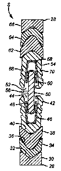
[0010] Figure 1 is a section view of a prior art seal for extreme temperature
and
pressure conditions;
[0011] Figure 2 is an early version of the present invention developed by the
inventors;
[0012] Figure 3 is a section view of the seal of the present invention in a
position
before extreme temperature and pressure conditions are applied;
[0013] Figure 4 is the view of Figure 3 shown under fully loaded conditions;
and
[0014] Figure 5 is a view showing how the seal of the present invention would
collapse if the central ring were to be omitted.
DETAILED DESCRIPTION OF THE PREFERRED EMBODIMENT
[0015] Referring to Figure 3, the seal S of the present invention is shown
without the
tool that it would be secured to. The seal bore into which the seal S is to be
inserted is also
omitted on the basis that those skilled in the art are readily familiar with
downhole tools and
seal bores into which seals such as seal S are inserted. For similar reasons,
the surface
wireline equipment and the wireline are omitted due to their familiarity to
the person skilled in
this art. It should be noted that seal S can be used on a subsurface safety
valve that can be
delivered on wireline. This is only the preferred use and those skilled in the
art will recognize
that the seal S can be used with a broad variety of tools and delivered
downhole in a variety of
ways other than a wireline. Seal S is preferably used in applications of
sealing in a seal bore
downhole under conditions of high pressure and temperature differentials. Seal
S can
withstand differentials in pressure in either direction in excess of 13,500
PSI and temperatures
well in excess of 350 degrees Fahrenheit.
[0016] The components will be described from the downhole end 26 to the uphole
end 28. A female adapter 30 has an uphole oriented notch 32, which is
preferably v-
shaped. Located in notch 32 is a chevron shaped ring 34 with a notch 36
oriented in
an uphole direction. Mounted in notch 36 is chevron shaped ring 38 with a
notch 40 oriented
in an uphole direction. Lower seal 42 sits in notch 40 and has an uphole
oriented opening 44
in which is disposed one or more generally u-shaped spring rings such as 46
and 48 that are
3a
CA 02486703 2007-03-12
shown stacked on each other with their respective openings oriented uphole.
Spring rings 46
and 48 are preferably mounted within opening 44 and in an abutting relation.
Inserted into
opening 44 and opening 52 of upper seal 54 is ring 50. Ring 50 has a radial
component 56
extending toward the downhole tool (not shown). Located preferably within
opening 52 are
stacked and abutting spring rings 58 and 60, which are preferably identical to
spring rings 46
and 48 except that they are disposed in a mirror image relation to them. In
fact, the upper
portion of the seal S above the ring 50 is the mirror image of the previously
described
components that are located below ring 50. In the preferred embodiment going
uphole or
downhole from ring 50 the hardness of the rings going from seal 42 to ring 38
to ring 34 is
progressively harder. The same goes for their mirror image counterparts, seal
54, ring 62, ring
64, and female adapter 66. The preferred material for the female adapters 30
and 66 is
InconelTM 718. For ring 64 and its counterpart ring 34 the preferred material
is virgin
polyetheretherketone. For ring 62 and its counterpart ring 38 the preferred
material is a PTFE
(TeflonTM) with 20% polyphenylenesulfide and some carbon. The preferred
material for the
seals 42 and 54 is a PTFE (TeflonTM) flourocarbon base with 15% graphite.
[0017] Seals 42 and 54 could have one ore more interior 68 or exterior 70
notches to
promote sealing contact with the tool (not shown) and the seal bore (not
shown) respectively.
These notches promote some flexibility in response to pressure or thermal
loads.
[0018] The operation of the seal S under a pressure differential from uphole
is
illustrated in Figure 4. Arrow 72 represents such pressure from uphole going
around seal 52
because its opening 52 is oriented downhole. The wings 74 and 76 flex toward
each other
responsive to the pressure differential. The seal 52 is moved with respect to
ring 50. This
movement allows the spring rings 58 and 60 to become more nested and to apply
a greater
spread force against wings 74 and 76. However, ring 50 also prevents collapse
of spring rings
4
CA 02486703 2004-11-16
WO 03/102360 PCT/US03/15697
58 and 60 because the described movement has resulted in positioning ring 50
in the openings
defines by generally u-shaped spring rings 58 and 60. For that same reason,
wings 74 and 76
are prevented from collapse toward each otller. Meanwhile, the pressure
represented by arrow
72 enters opening 44 with the result that ring 50 is pushed into spring rings
46 and 48 to not
only splay apart the wings 78 and 80 but also to keep such wings from
collapsing and
permanently deforming due to movement of ring 50 into the openings defined by
nested spring
rings 46 and 48. Ring 50 pushes the spring rings 46 and 48 into a more nested
relation but at
the same time, its presence in their openings prevents collapse of not only
spring rings 46 and
48 but also of wings 78 and 80 to their immediate exterior. Another benefit of
ring 50 is that it
is of the appropriate length to prevent wings 74 and 76 from contacting wings
78 and 80 under
maxinlum loading conditions. Contact at such high temperatures and pressures
could fuse the
wings together with a seal failure being a possibility. This is illustrated in
Figure 5 where the
ring 50 has been eliminated and wings 74 and 76 have contacted wings 78 and
80. The spring
rings in Figure 5 have all buckled and are permanently deformed. This seal is
likely to be in
failure mode.
[0019] Another advantage of having the ring 50 is that upon insertion of the
downlzole
end of seal S into a seal bore, ring 50 adds some rigidity to that portion of
seal S already
inserted into the seal bore to act as a centralizer for the reinaining
portions of seal S to facilitate
its insertion without damage. Radial component 56 also helps in the
centralizing function for
insertion of seal S into a seal bore (not shown).
[0020] Those skilled in the art will appreciate that while Figure 4
illustrates a pressure
differential from uphole that the response of seal S to a differential
pressure from downhole is
essentially the mirror image of what was described as the situation in Figure
4. The design of
seal S is unique in high temperature and pressure service and one such feature
is the internal
spring component. While spring rings having a generally u-shaped cross-section
have been
illustrated other cross-sectional shapes for the spring rings are contemplated
as long as the
response is to splay out the wings while exhibiting resiliency to return to a
neutral position
when the extreme pressure or temperature conditions are removed. The use of a
separation ring
to lceep the wings apart and to prevent their collapse and the collapse of the
spring rings inside
them allows the seal S to withstand cycles of temperature and pressure
extremes and continue
to be serviceable. The placement of the components in a nesting relation in
conjunction with
ring 50 a.nd radial component 56 helps to centralize seal S with respect to
the downhole tool to
which it is mounted as well as to facilitate its insertion into a seal bore.
This is because the
CA 02486703 2004-11-16
WO 03/102360 PCT/US03/15697
downhole end 26, upon entering the seal bore centralizes the seal S so that
the rest ot it is
simply advanced into the seal bore without damage.
[0021) While the seal S is ideal for high pressure and teniperature
applications, it caxi
also be serviceable in less severe enviromnents and can be delivered into a
seal bore by a
variety of conveyances such as coiled tubing, rigid pipe as well as wireline,
among others. Its
construction makes it easily insertable in a wireline application, when
minimal force is
available get the seal S into the seal bore.
[0022] The foregoing disclosure and description of the invention are
illustrative and
explanatory tliereof, and various changes in the size, shape and materials, as
well as in the
details of the illustrated construction, may be made witliout departing from
the spirit of the
invention.
6