Note : Les descriptions sont présentées dans la langue officielle dans laquelle elles ont été soumises.
CA 02487876 2004-11-18
FREQUENCY CHARACTERIZATION OF QUARTZ CRYSTALS
Background of Invention
Field of the Invention
[0001] The invention relates generally to the field of quartz crystals used as
highly stable
frequency standards (such as clocks). More particularly, the invention relates
to
techniques for profiling or characterizing the frequency output of crystal-
based oscillators
with reduced deviations in frequency due to environmental effects.
Background Art
[0002] Timing of operation of electronic devices, particularly digital
devices, requires an
accurate, frequency stable clock signal. Many such electronic devices are
subjected to
variations in ambient temperature during their operation. As is well known in
the art,
changes in ambient temperature affect the frequency of a typical crystal.
[0003] While quartz oscillators are considerably more stable when compared to
other
types of oscillators, their frequency output is known to exhibit some drift
under rapid
temperature variations. The effect of stresses on quartz crystals is well
known and
exploited in the design of quartz based stress and pressure sensors. Due to
the low
thermal conductivity and the anisotropic properties of quartz, heating and
cooling crystals
is known to cause stresses in the crystal, which affects the frequency. See,
Bottom,
Virgile E. Introduction to Quartz Crystal Unit Design, New York: D. Van
Nostrand,
1982. For this reason, it is generally not recommended to subject quartz
crystals to rapid
temperature gradients.
[0004] In conventional applications the frequency deviations of quartz
crystals due to
temperature are profiled or characterized during manufacture and compensated
for in real
time. Rapid temperature fluctuations in the crystal's environment and changing
temperature rates, also referred to as temperature gradients, cause the
crystal frequency to
deviate from the characterization. Though the varying temperature rates may
last for a
brief period, their effects can last for long periods of time, causing
measurement errors.
1
CA 02487876 2004-11-18
[0005] In order to achieve greater frequency stability, several methods have
been
proposed to account for these deviations. One approach is to place the crystal
in a
temperature controlled chamber, which will keep the crystal at a constant
temperature
and prevent any deviation in frequency. See, for example, U.S. Pat. Nos.
5,917,272,
5,729,181, 5,180,942, 4,586,006 and 3,619,806. Another approach taken to
compensate
for the deviations in frequency due to temperature is to use a voltage-
controlled oscillator
of which the frequency can be adjusted by changing the voltage at the control
input. In
these designs, the temperature at the crystal is measured and used to
digitally compute a
correction voltage to be applied to the voltage-controlled oscillator. See,
for example,
U.S. Pat. Nos. 5,668,506, 5,473,289, 5,214,668, 5,170,136, 5,081,431,
4,922,212,
4,746,879, 4,427,952 and 4,380,745.
[0006] One problem with using a temperature sensor and measuring the
temperature
outside the crystal is that there is a time lag between the actual crystal
temperature (at the
quartz plate) and the outside where the temperature is measured. This causes
the
oscillators to be slow in responding to a change in temperature, introducing
errors. A
proposed solution to this problem is to have the crystal oscillate in two
modes
simultaneously, where one of the two modes is temperature sensitive while the
second
mode is relatively stable with temperature. The temperature sensitive mode is
used to
obtain the temperature at the crystal itself and then used to compensate for
minor
deviations with temperature in the stable mode. See, for example, U.S. Pat.
Nos.
5,525,936 and 4,079,280. In spite of the very accurate measurement of
temperature in
these designs, high temperature gradients in the environment still introduce
errors.
Modem crystals are also cut at special angles, such as the SC cut, in an
attempt to
minimize frequency deviation due to temperature.
[0007] Another method that can be used to minimize problems due to fluctuating
temperature rates is to place the crystal in a temperature controlled chamber.
See, for
example, U.S. Pat. No. 6,606,009 (assigned to the present assignee). However,
this
option entails higher power consumption, which can be a disadvantage in
certain
applications. Thus a need remains for improved techniques to account for and
minimize
frequency deviation in crystal-based oscillators due to environmental
variations.
2
CA 02487876 2007-10-19
79350-130
Summary of the Invention
According to the present invention, there is
provided a method for determining a frequency profile of a
quartz crystal, comprising: a) subjecting the quartz
crystal to temperature cycles at various temperature rates;
b) monitoring the crystal frequencies, a crystal temperature
parameter, and the temperature rates as the crystal is
subjected to the temperature cycles; c) grouping the
monitored frequencies correlated with the monitored
temperature parameters and temperature rates; and d)
characterizing the crystal frequency (f) as a function of
the monitored temperature parameters and temperature rates
according to
.f = .f (T,T ),
where T is a temperature parameter and
_ dT
T
dt
Also according to the present invention, there is
provided a method for determining a frequency of a quartz
crystal, comprising: a) subjecting the quartz crystal to
temperature cycles at various temperature rates; b)
monitoring the crystal frequencies, a crystal temperature
parameter, and the temperature rates as the crystal is
subjected to the temperature cycles; c) grouping the
monitored frequencies correlated with the temperature
parameters and temperature rates; d) characterizing the
crystal frequency (f) as a function of the monitored
temperature parameters and temperature rates according to
3
CA 02487876 2007-10-19
79350-130
f = .f (T, T ),
where T is a temperature parameter and
. dT
T=-;
dt
e) determining the temperature and a temperature rate of the
crystal; and f) relating the determined crystal temperature
and temperature rate to the characterized frequencies to
determine the crystal frequency.
According to the present invention, there is
further provided a method for determining a frequency of a
quartz crystal disposed in a tool adapted for subsurface
disposal, comprising: a) determining a temperature of the
quartz crystal in said tool; b) deriving a temperature rate
from the determined crystal temperature; and c) relating the
crystal temperature and temperature rate to a data set
characterizing a correlation between grouped crystal
frequencies (f), temperature, and temperature rates to
determine the crystal frequency according to
f = .f (T,T ),
where T is a temperature parameter and
T=dT
dt
According to the present invention, there is
further provided a system for determining the frequency of a
quartz crystal, comprising: a quartz crystal having a
frequency output related to a temperature of the crystal;
and a processor adapted to calculate a crystal frequency
4
CA 02487876 2007-10-19
79350-130
from a measured temperature parameter of the crystal, a
temperature rate of the crystal, and observed frequencies of
the crystal grouped with observed temperature parameters and
temperature rates of the crystal; wherein the processor is
adapted to characterize a relationship between the crystal
frequency (f) and the observed temperature parameters and
temperature rates according to
f = .f (T ,T ),
where T is a temperature parameter and
T=dT
dt
[0008] An aspect of the invention provides a method for
determining a frequency profile of a quartz crystal. The
method includes subjecting the quartz crystal to temperature
cycles at various temperature rates; monitoring the crystal
frequencies, a crystal temperature parameter, and the
temperature rates as the crystal is subjected to the
temperature cycles; and grouping the monitored frequencies
correlated with the monitored temperature parameters and
temperature rates.
[0009] An aspect of the invention provides a method for
determining a frequency of a quartz crystal. The method
includes determining a temperature of the quartz crystal;
deriving a temperature rate from the determined crystal
temperature; and relating the crystal temperature and
temperature rate to a data set characterizing a correlation
between the crystal frequency, temperature, and temperature
rates to determine the crystal frequency.
4a
CA 02487876 2007-10-19
79350-130
[0010] An aspect of the invention provides a system for
determining a frequency of a quartz crystal. The system
includes a crystal having a frequency output related to a
temperature of the crystal; and a processor adapted to
calculate a crystal frequency from a measured temperature
parameter of the crystal, a temperature rate of the crystal,
and observed frequencies of the crystal correlated with
observed temperature parameters and temperature rates of the
crystal.
Brief Description of the Drawings
[0011] Examples of embodiments of the invention will now
be described with reference to the drawings in which:
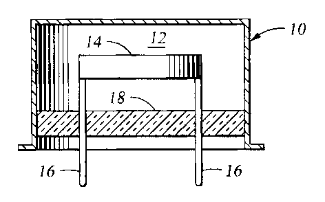
[0012] FIG. 1 is a cross-section of a quartz crystal
package in accordance with an embodiment of the invention.
[0013] FIG. 2 is an overhead detailed view of the quartz
crystal of FIG. 1.
[0014] FIG. 3 is a plot of crystal temperature cycles of
varying temperature gradients in accordance with an
embodiment of the invention.
[0015] FIG. 4 is a plot of the temperature and
temperature gradients of FIG. 3.
[0016] FIG. 5 is a plot of crystal frequency as a
function of temperature and temperature rate depicted as a
surface within Cartesian 3-D space.
[0017] FIG. 6 is an overhead view of a quartz crystal in
accordance with an embodiment of the invention.
4b
CA 02487876 2007-10-19
79350-130
[0018] FIG. 7 shows a downhole logging system disposed in
a borehole and equipped with a crystal oscillator in
accordance with an embodiment of the invention.
[0019] FIG. 8 illustrates a flow chart of a process for
determining a frequency profile of a quartz crystal
oscillator in accordance with an embodiment of the
invention.
[0020] FIG. 9 illustrates a flow chart of a process for
determining a frequency of a quartz crystal oscillator in
accordance with an embodiment of the invention.
[0021] FIG. 10 illustrates a flow chart of a process for
determining a frequency of a quartz crystal oscillator in
real time in accordance with an embodiment of the invention.
Detailed Description
[0022] In quartz crystal oscillator applications that
require significant frequency stability, the temperature
dependency of the frequency is typically profiled or
characterized during manufacturing and captured in the form
of a polynomial or look up table. During characterization,
a crystal is subjected to a temperature cycle while the
frequency and temperature are monitored. A temperature
cycle involves heating from the lowest to highest operating
temperature and then cooling down from highest to lowest
temperature. The repeatability of the crystal frequency
response is crucial to the success of high stability
applications. If the crystal were perfect, the frequency
response during heating would theoretically match perfectly
with the frequency response during cooling. In reality,
however, a crystal's responses do not match perfectly. This
effect, sometimes referred to as hysteresis, causes the
4c
CA 02487876 2007-10-19
79350-130
response during heating to be slightly different from that
during cooling. This effect is referred to as temperature
rate/gradient effects in this disclosure as a strong
dependency of this effect on the rate of heating or the
temperature rate has been observed.
[0023] An example of a basic quartz crystal device that
may be used to implement various aspects of the invention is
shown generally in FIG. 1. A quartz plate or disc 14 is
4d
CA 02487876 2004-11-18
attached to mounting clips/electrical leads 16. The disc 14 is disposed within
a housing
and sealed therein by an insulating layer 18 (e.g. glass layer). The housing
10 is
preferably evacuated to form a vacuum area 12 for the quartz disc 14 and
surroundings.
Electrical connections to electrodes on the disc 14 are made via the leads 16
passing
through the insulating layer 18. Although FIG. 1 shows one sample quartz
crystal device,
it will be appreciated by those skilled in the art that there are many
standard package
styles/configurations used in mounting quartz crystals. Further description of
quartz
crystal packages is found in Griffith, James E., "Development And Advancements
in SC-
Cut Crystals", RF Expo EAST, 1994, (http://www.corningfrequency.com).
[0024] FIG. 2 shows a more detailed view of the quartz disc 14 as viewed from
above.
The disc 14 has two metal electrodes, one electrode 24 on the top surface and
the other 22
on the bottom surface, to provide the electrical stimulus to make the disc
vibrate. The
electrodes 22, 24 are disposed on the disc 14 by means well known in the art.
The disc
14 housing 10 is metallic, which is typical for conventional crystal packages.
[0025] When one considers the characterization cycle where the crystal is
heated, one
can expect the metal housing 10 to heat first and then the disc 14. In this
situation, since
the area inside the housing 10 is a vacuum, the strongest heat flow is
expected through
the mounting clips/leads 16 connected to the electrodes 22, 24 as they are
made of metal,
which conducts heat well. Therefore, when one considers the temperature
distribution of
the quartz disc 14, one can expect the immediate areas close to the connected
leads 16 to
get hotter while areas further away from the leads remain relatively cooler
since quartz is
generally a poor heat conductor. Note that the mounting clips 16 not used as
leads for the
electrodes 22, 24 may be non-metallic in some designs. One can expect the
hottest disc
14 areas to expand most due to thermal expansion and the colder areas to
expand less.
This type of mismatch in expansion is likely to induce mechanical stresses,
causing
changes in the vibrating frequency.
[0026) During the cooling part of the cycle, the housing 10 exterior is colder
relative to
the disc 14 and heat flows in the opposite direction through the leads 16.
Thus in this
situation, the area further away from the leads 16 will be hot and expanded
while the area
closer to the leads will be cooler and contracting. This reversal in stress
states affects the
5
CA 02487876 2007-12-14
79350-130
crystal, causing frequency shifting in one direction during heating and in the
opposite
direction during cooling. These stresses induced by non-uniform teinperature
distributions are key factors in quartz crystal frequency shifts, producing
frequency
gradient effects.
[0027] As previously discussed, conventional methods of compensating for
deviations in
quartz oscillator frequency output due to temperature are characterized as
f =f(T), (1)
where f represents frequency and T the temperature. Manufactured crystals are
subjected
to a temperature cycle while the frequency and temperature are measured. This
data is
used to compute Equation (1) by optimization. This function is typically
represented as a
polynomial:
f(T)arV, (2)
i=o
and the coefficients are computed by optimization (polynoinial fit to the
data) using the
characterization data. These coefficients are typically stored and used to
compute the
actual frequency of the oscillator by measuring the temperature.
[0028] Techniques of the present invention account for temperature gradient
effects on
the crystal by performing a two-dimensional characterization where the two
dimensions
are a teniperature parameter and temperature rate. The temperature parameter
may be
any parameter representative of temperature. In one embodiment the temperature
paranieter is the ratio of frequencies (Fb/Fc) as described in U.S. Pat. No.
6,606,009,
with the temperature rate being captured by the time derivative of the
parameter. In
one process of the invention, the characterization involves subjecting the
quartz
crystal 14 to multiple tenzperature cycles witli varying temperature rates.
The crystal
fi-equency is then characterized as a function of both the teinperature pai-
ameter and
tenlperatui-e rate as follows:
.f=f(T,T), T= ~T > (3)
6
CA 02487876 2004-11-18
where f represents frequency, T represents the temperature or any parameter
representing
temperature, T represents a time derivative of T, and t represents time. The
characterization can be represented by a polynomial or look up table which may
be used
in real time to compute the crystal frequency.
[0029] In the two-dimensional approach of the invention, a crystal is
subjected to a series
of temperature T cycles 1, 2, 3, 4, 5, 6 of varying temperature rates, as
shown in FIG. 3.
During these cycles the state of the crystal can be considered as going
through the curve
shown in FIG. 4 on a plot of temperature T versus temperature rate T for a
simple case
where the heating and cooling rates are the same. Looking at temperature cycle
I in FIG.
3, the temperature is increasing at a constant rate (e.g. 20 degrees/hour),
thus the
corresponding curve 1(rate T) in FIG. 4 is a positive constant as the
temperature T
increases. In the cooling cycle 2, curve 2 (FIG. 4) remains constant as the
temperature T
decreases, but it is now a negative rate. For the next cycle 3, the
temperature rate is
higher as represented by curve 3 in FIG. 4, and so forth.
[0030] As the crystal 14 is subjected to the temperature cycles, the
frequency,
temperature parameter, and temperature rate are monitored and recorded. This
characterization data can be graphed to define the shape of a surface within
Cartesian
three-dimensional space using a standard mathematical function of two real
variables
which assigns a unique real number or point z = f(x, y) to each ordered pair
(x, y) of real
numbers in the recorded data set. In this case, the ordered pair consists of
the monitored
temperature parameters T and temperature rates T.
100311 As shown in FIG. 5, the crystal frequencies can be pictured as a set of
points
(T,T) in the xy plane and the graph of the frequency function as the surface f
= f(T,T) .
Thus as the point (T,T) varies in the data set domain, the corresponding point
(x, y, z) =
(T,T, f(T,T)) varies over the surface. Any suitable software may be used to
process the
data set and plot the surface as known in the art. Interpolation or
extrapolation
techniques known in the art may be used to derive missing points in the
surface
f = f(T, T). Once the surface is generated, it can be used in real time to
compute the
7
CA 02487876 2004-11-18
frequency more accurately by computing the temperature parameter T and
temperature
rate 7' .
[0032] Undesired gradient effects can also be reduced or eliminated by making
the
crystal 14 temperature distribution more uniform. FIG. 6 shows another
embodiment of
the invention. In this embodiment a dummy plating 26 is disposed on the quartz
disc 14
surface to improve heat conduction across the disc. One or both sides of the
disc 14 may
be equipped with the plating 26. Any suitable heat conductor may be used for
the plating
26 material (e.g. metal, which is good heat conductor). The plating 26 may be
disposed
on the disc 14 via any suitable means known in the art (e.g. electroplating,
vapor
deposition, etching, adhesives, etc.). Sufficient clearance should be left
between the
dummy plating 26, the mounting clips/leads 16, and the electrodes 22, 24 to
prevent
electrical shorts. Some embodiments may be implemented with bigger electrodes
22, 24
to cover a larger portion of the quartz disc 14 surface (not shown).
100331 It will be appreciated by those of ordinary skill in the art that the
present invention
is applicable to, and can be implemented in, any field where quartz crystal
oscillators are
used as frequency standards (e.g. in apparatus for use in outer space,
automobiles, etc.).
While not limited to any particular application, the present invention is
suitable for
subsurface applications, where rapid temperature variations are encountered.
[0034] FIG. 7 shows another embodiment of the invention. A quartz crystal
oscillator 48
is shown mounted in a downhole logging tool 28 disposed in a borehole 30 that
penetrates an earth formation. The oscillator 48 is housed within a thermally
insulated
chamber 50 to reduce heat flow to the crystal during heating and cooling. The
chamber
50 provides thermal insulation through the use of conventional insulating
materials or by
using a dewar flask as known in the art and described in U.S. Pat. No.
6,606,009. The
tool 28 also includes a multi-axial electromagnetic antenna 19, a conventional
source/sensor 44 array for subsurface measurements (e.g., nuclear, acoustic,
gravity), and
electronics 42 with appropriate circuitry. The tool 28 is shown supported in
the borehole
30 by a logging cable 36 in the case of a wireline system or a drill string 36
in the case of
a while-drilling system. With a wireline tool, the tool 28 is raised and
lowered in the
borehole 30 by a winch 38, which is controlled by the surface equipment 32.
Logging
8
CA 02487876 2004-11-18
cable or drill string 36 includes conductors 34 that connect the downhole
electronics 42
with the surface equipment 32 for signal and control communication.
Alternatively, these
signals may be processed or recorded in the too128 and the processed data
transmitted to
the surface equipment 32.
[0035] It will also be apparent to those skilled in the art that this
invention may be
implemented by programming one or more suitable general-purpose
microprocessors.
The programming may be accomplished through the use of one or more program
storage
devices readable by the processor and encoding one or more programs of
instructions
executable by the processor for performing the operations described above. The
program
storage device may take the form of, e.g., one or more floppy disks; a CD ROM
or other
optical disk; a magnetic tape; a read-only memory chip (ROM); and other forms
of the
kind well-known in the art or subsequently developed. The program of
instructions may
be "object code," i.e., in binary form that is executable more-or-less
directly by the
processor; in "source code" that requires compilation or interpretation before
execution;
or in some intermediate form such as partially compiled code. The precise
forms of the
program storage device and of the encoding of instructions are immaterial
here. Thus
these processing means may be implemented in the surface equipment 32, in the
too128,
or shared by the two as known in the art.
[0036] An embodiment of the invention relates to a process for determining a
frequency
profile of a quartz crystal. FIG. 8 outlines the process. First the quartz
crystal is
subjected to temperature cycles at various temperature rates (step 100). This
step may be
performed during manufacture of the crystal or at any suitable location (e.g.,
a laboratory,
a field location, etc.). Next, the crystal frequencies, a crystal temperature
parameter, and
the temperature rates are monitored as the crystal is subjected to the
temperature cycles
(step 105). Then a grouping is done of the monitored frequencies correlated
with the
monitored temperature parameters and temperature rates (step 110). The data
grouping
may be performed using processor means or any other suitable means known in
the art.
[0037] FIG. 9 is a flow chart illustrating a process for determining a
frequency of a
quartz crystal according to the invention. The process begins by subjecting
the quartz
crystal to temperature cycles at various temperature rates (step 200). At step
205, the
9
CA 02487876 2004-11-18
crystal frequencies, a crystal temperature parameter, and the temperature
rates are
monitored as the crystal is subjected to the temperature cycles. Then the
monitored
frequencies correlated with the temperature parameters and temperature rates
are grouped
(step 210). At step 215, the crystal temperature and a temperature rate of the
crystal are
determined. The temperature and rate determination is performed using any
means
known in the art and suitable for the particular environment. Finally, the
determined
crystal temperature and temperature rate are related to the grouped
frequencies to
determine the crystal frequency (step 220). This association is performed as
described
herein using microprocessor means or any other suitable means known in the
art.
[0038] FIG. 10 is a flow chart illustrating a process for determining a
frequency of a
quartz crystal in real time according to the invention. The process begins by
determining
a temperature of the quartz crystal (step 300). The crystal temperature may be
determined using any suitable means known in the art and appropriate for the
particular
crystal environment. A temperature rate is then derived from the determined
crystal
temperature (step 305). At step 310, the crystal frequency is determined by
relating the
crystal temperature and temperature rate to a data set characterizing a
correlation between
the crystal frequency, temperature, and temperature rates. The data set is
compiled as
described herein.