Sélection de la langue

Search

Sommaire du brevet 2488235 

Énoncé de désistement de responsabilité concernant l'information provenant de tiers

Une partie des informations de ce site Web a été fournie par des sources externes. Le gouvernement du Canada n'assume aucune responsabilité concernant la précision, l'actualité ou la fiabilité des informations fournies par les sources externes. Les utilisateurs qui désirent employer cette information devraient consulter directement la source des informations. Le contenu fourni par les sources externes n'est pas assujetti aux exigences sur les langues officielles, la protection des renseignements personnels et l'accessibilité.

Disponibilité de l'Abrégé et des Revendications

L'apparition de différences dans le texte et l'image des Revendications et de l'Abrégé dépend du moment auquel le document est publié. Les textes des Revendications et de l'Abrégé sont affichés :

  • lorsque la demande peut être examinée par le public;
  • lorsque le brevet est émis (délivrance).
(12) Demande de brevet: (11) CA 2488235
(54) Titre français: TUBES DE RACCORDEMENT RAPIDE A SURFACE PLANE INSTALLES ENTRE UN DISPOSITIF UTILISATEUR DE FLUIDE SOUS PRESSION ET UN DISPOSITIF D'ALIMENTATION EN FLUIDE
(54) Titre anglais: FLAT-SURFACE QUICK COUPLING TUBES EXTENDING BETWEEN A PRESSURIZED FLUID USER DEVICE AND A FLUID FEEDING MEANS
Statut: Réputée abandonnée et au-delà du délai pour le rétablissement - en attente de la réponse à l’avis de communication rejetée
Données bibliographiques
(51) Classification internationale des brevets (CIB):
  • F16L 37/56 (2006.01)
  • F16L 37/10 (2006.01)
  • F16L 39/00 (2006.01)
(72) Inventeurs :
  • AROSIO, MASSIMO (Italie)
(73) Titulaires :
  • FASTER, S.P.A.
(71) Demandeurs :
  • FASTER, S.P.A. (Italie)
(74) Agent: GOWLING WLG (CANADA) LLP
(74) Co-agent:
(45) Délivré:
(22) Date de dépôt: 2004-11-23
(41) Mise à la disponibilité du public: 2005-06-02
Requête d'examen: 2005-04-11
Licence disponible: S.O.
Cédé au domaine public: S.O.
(25) Langue des documents déposés: Anglais

Traité de coopération en matière de brevets (PCT): Non

(30) Données de priorité de la demande:
Numéro de la demande Pays / territoire Date
MI2003 A 002348 (Italie) 2003-12-02

Abrégés

Abrégé anglais


A flat-surface quick coupling for coupling tubes extending
between a pressurized fluid user device and fluid feeding means
comprises a quick coupling (2) female part (1) and a quick
coupling (2) male part (12), to which are coupled concentric
tubes for providing a delivery duct and a return duct for a
hydraulic fluid, the ducts delimited by the concentric tubes being
operatively coupled to a delivery duct, respectively a return duct,
made inside the quick coupling parts (1) and (12), said ducts,
upon assembling the female part (1) and male part (12) being
mutually operatively connected.

Revendications

Note : Les revendications sont présentées dans la langue officielle dans laquelle elles ont été soumises.


-9-
Claims
1. A flat-surface quick coupling for coupling tubes extending
between a pressurized fluid user device and a fluid feeding
means, characterized in that said quick coupling (2) comprises a
quick coupling female part (1) and a quick coupling male part
(12) to which are connected concentric tubes (5, 10, 15, 20) so
as to provide a hydraulic fluid delivery duct (6, 16) and a
hydraulic fluid return duct (11, 37), and that the ducts defined by
said concentric tubes (5, 10, 15; 20) are operatively coupled to a
fluid delivery duct (7) respectively a fluid return duct (17)
provided inside said female part (1) and male part (12) and that
said ducts (7, 17), upon assembling said male and female parts
(11, 12), are mutually operatively connected.
2. A flat-surface quick coupling according to claim 1,
characterized in that said male part (12) rotatively houses a ring
nut (21) adapted to be locked at an axial position thereof by a
resilient ring element (22), and that said ring-nut (21) comprises
a front inner thread (23) to be coupled with a thread (24) of said
female part (1).
3. A flat-surface quick coupling according to claim 1,
characterized in that said stem (25) operates as a guide element
for a movable tubular element (31) including a circumferential
enlarged portion (32) thereagainst abuts a spring (33)

-10-
encompassed, on a front side thereof, by a movable ring gear
(34), said ring gear (34) being brought into abutment with an
outer tubular body (36) of said female part (1).
4. A flat-surface quick coupling according to claim 1,
characterized in that said mate part (12) supports in an inside
thereof, through and enlarged portion (18), a locally fixed tubular
element (40) and that against said tubular element (40) abuts a
spring (41) thereagainst abuts an enlarged portion (42) of an
axially movable tubular element (43), which, on a front side
thereof, is encompassed by a spring (44) thereagainst a further
tubular element (45) bears.

Description

Note : Les descriptions sont présentées dans la langue officielle dans laquelle elles ont été soumises.

CA 02488235 2004-11-23
_1 _
Description of the industrial invention entitled: "Flat-surface quick
coupling tubes extending between a pressurized fluid user device
and a fluid feeding means".
Background of the invention
The present invention relates to a flat-surface quick coupling for
coupling tubes extending between a pressurized fluid user device
and a fluid feeding means.
Is already known in the prior art to use quick couplings for
coupling flexible hoses to an user device; such as an actuator
device provided in an agricultural apparatus or a civil building
apparatus, for example a grader or an excavator.
Actually, in these machines resilient tubes or hoses for supplying
through a delivery tube a hydraulic fluid, e.g. a highly pressurized
oil, to an user, such as a cylinder/piston unit or hydraulic motor,
are used.
To recover or return the hydraulic fluid from the user to the
pressure source, such as a pump, it is indispensable to also
provide a fluid return tube.
Thus, from the prior art is already known to use two separated
flexible tubes or hoses provided, at their end portions, with quick
couplings for coupling an user device t~ a pressure source.

CA 02488235 2004-11-23
-2-
It is moreover frequently necessary to disconnect the fluid
delivery tube and fluid return tube from a set user, for example to
replace an operating tool, or to carry out servicing operations to
said operating tool.
Considering that in the past it was conventional to use two
separated tubes having a delivery function, respectively a return
function, and considering that the coupling operations were to be
performed in dirty environments and, moreover, that the
pressurized fluid tube connecting operations were to be
performed with a comparatively high speed, the delivery tube
could be erroneously connected to a hydraulic fluid return fitting
or vice versa, with the risk of a failure of the auxiliary apparatus
or of irreparable damages.
Finally, a further drawback of prior quick coupling for coupling a
delivery tube separated from a return tube, was the necessity of
providing two pairs of quick couplings, thereby greatly increasing
the system cost.
Summary of the invention
The main object of the present invention is to overcome the
above mentioned drawbacks of the prior art, by allowing to use a
single, quick coupling, both for the pressurized fluid delivery line
and return line, while allowing a quick and simple coupling to be

CA 02488235 2004-11-23
-3-
obtained, while absolutely preventing any assembling errors in
resilient tube connecting operations from occurring.
The above object is achieved by a flat-surface quick coupling for
coupling tubes extending between a pressurized fluid user device
and a fluid feeding means, characterized in that to a female part
of the flat-surface quick coupling and a male part of said flat-
surface quick coupling are coupled mutually concentric tubes to
provide a hydraulic fluid delivery duct and a hydraulic fluid return
duct, and that the ducts delimited by said concentric tubes are
operatively coupled to a fluid delivery duct, respectively a fluid
return duct, said ducts being made inside said female quick
coupling part and male quick coupling part, and that said ducts,
upon assembling said quick coupling parts, are mutually
operatively connected.
Brief description of the drawings
The subject matter according to the present invention will be
disclosed in a more detailed manner hereinafter and illustrated
by an embodiment thereof, given only by way of an example, and
shown in the accompanying drawings, where:
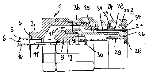
Figure 1 is a partially cross-sectioned view illustrating the female
part of the novel quick coupling;
Figure 2 is a partially cross-sectioned view illustrating the male

CA 02488235 2004-11-23
_4~
part of the novel quick coupling;
Figure 3 is a partially cross-sectioned view showing. the
components of the quick coupling at the start of the coupling
operation or step;
Figure 4 is a partially cross-sectioned view illustrating the quick
coupling components in an operatively connected condition; and
Figure 5 shows the quick coupling components at the end of the
connecting operation or step, with the flow ducts in an opened
condition to allow the hydraulis fluid to flow therethrough.
Description of the preferred embodiments
As shown in figure 1, the female part 1 of the flat-surface quick
coupling, generally indicated by 2, comprises an end fitting 3,
including an inner recess 4 for engaging therein an end portion of
a resilient tube or hose 5, defining a first annular duct 6.
The annular duct 6 is coupled to a further duct 7 formed inside
the body of the female part 1.
Inside said female part 1 is provided a ring-nut 8 defining a
recess 9 for engaging therein an end portion of a second resilient
tube or hose 10, leading to a duct 11 formed inside said female
part 1.
The fluid delivery and return tubes 5 and 10 are arranged
coaxially with respect to one another.

CA 02488235 2004-11-23
_5_
Figure 2 is a partially cross-sectioned view showing the male part
12 of the quick coupling, also indicated by the reference number
The quick coupling 2 comprises an end fitting 13 having an inner
recess 14 in which is engaged a flexible hose or tube 15 defining
a first hydraulic fluid flow duct 16 leading to a duct 17 delimited
by an insert 18, including a recess 19 therein is engaged an end
portion of a further flexible tube or hose 20 defining a further duct
37.
The fitting 12 rotatably houses a ring-nut 21 locked at an axial
position by a resilient ring element 22.
The rotary ring-nut 21 comprises, on a front side thereof, an inner
thread 23 allowing the two quick coupling parts 1, 12 to be
coupled, as the ring nut 21 is screwed on the outer thread 24 of
the female part 1.
The coupling steps for coupling the female part 1 and male part
12 are shown in figures 3, 4 and 5.
Figure 1 shows moreover that the female part 1 comprises a
locally fixed inner tubular stem 25, known per se in the prior art.
The tubular stem 25 operates as a separating element for the
ducts 7, 11. As shown, the stem 25 comprises a front enlarged
portion engaging an inner annular gasket 26, and an outer
annular gasket 27.

CA 02488235 2004-11-23
_6_
The inner annular gasket 26 is contacted by a tubular sliding ring
nut 28, urged by an urging preloaded spring 29 bearing against a
perforated bush 30, rigid with the end portion of the stem 25.
Against the outer annular gasket 27 is abutted a movable tubular
element 31, having a circumferential enlarged or bulged portion
32; thereagainst abuts a spring 33 which on a front side.thereof
is encompassed by a movable ring gear 34 which, at an
abutment point 35; abuts against an outer tubular body 36 of the
female part 1.
Figure 2 shows that the quick coupling male part 12 supports in
its inside, through the enlarged portion 18; a tubular element 40
which is locally fixed.
Against said tubular element 40 abuts a spring 41, thereagainst
abuts an enlarged portion 42 of an axially movable tubular
element 43 and which, on the front side thereof, is encompassed
by a spring 44 thereagainst a further tubular element 45 abuts.
Between the tubular element 43, the tubular element 45 and front
end portion of the body 46, a series of gaskets 47 and 48 are
provided.
The constructional elements 42, 43 and 45 are held in their
proper position by a central stem 50.
At the start of the coupling operation for coupling the quick
coupling parts 1 and 12, as shown in figure 3, the thread 23 of

CA 02488235 2004-11-23
-7-
the rotary ring nut 21 is brought into engagement with the outer
thread 24 of the tubular body 36. All the movable elements 34;
28 and 31 as well as 45 and 43, by way of an example, are yet in
their starting positions and the ducts 7, respectively 17, are shut-
off, and, accordingly, no delivery or return hydraulic fluid flow will
occur therethrough.
By further screwing on the ring nut 21 of the thread 24, the stem
25 causes the tubular body 45 to be backward displaced against
a spring 44, which will be consequently preloaded. In the
meanwhile; the tubular body 43 is also moved backward against
an urging spring 41 which is also preloaded.
This effect is obtained since the tubular elements 45 is driven by
the stem 25 included in the female part 1. Simultaneously the
tubular element 43, sliding along a stem 50 which is locally fixed
inside the male part 12, is axially displaced, thereby disengaging
the duct 9.
In figure 5, the female part 1 is fully coupled to the male part 12.
Owing to the operation of the locally fixed stem 25, the body 45
has been backward displaced against the urging spring 44 which
is preloaded and, owing to the operation of the body 46, also the
ring nut 34 and tubular body 31 will have been driven toward the
rear or back part of the female part 1, thereby disengaging or
clearing the duct 7 while allowing an unhindered hydraulic fluid

CA 02488235 2004-11-23
_ 8
flow through the duct 7, in the direction indicated by the arrows
{f) in figure 5.
Simultaneously, since also the duct 9 has been fully cleared, it
will be possible to provide return fluid, as shown by the arrows
(g) in figure 5.
Thus, a quick coupling 2 including the quick coupling parts 1 and
12 allows, for the first time, to use concentric tubes 5 and 10, and
thereby allowing a delivery flow and a return flow inside a single
quick coupling 2.

Dessin représentatif
Une figure unique qui représente un dessin illustrant l'invention.
États administratifs

2024-08-01 : Dans le cadre de la transition vers les Brevets de nouvelle génération (BNG), la base de données sur les brevets canadiens (BDBC) contient désormais un Historique d'événement plus détaillé, qui reproduit le Journal des événements de notre nouvelle solution interne.

Veuillez noter que les événements débutant par « Inactive : » se réfèrent à des événements qui ne sont plus utilisés dans notre nouvelle solution interne.

Pour une meilleure compréhension de l'état de la demande ou brevet qui figure sur cette page, la rubrique Mise en garde , et les descriptions de Brevet , Historique d'événement , Taxes périodiques et Historique des paiements devraient être consultées.

Historique d'événement

Description Date
Le délai pour l'annulation est expiré 2009-11-23
Demande non rétablie avant l'échéance 2009-11-23
Réputée abandonnée - omission de répondre à un avis sur les taxes pour le maintien en état 2008-11-24
Modification reçue - modification volontaire 2008-07-08
Inactive : Dem. de l'examinateur par.30(2) Règles 2008-01-08
Inactive : CIB de MCD 2006-03-12
Demande publiée (accessible au public) 2005-06-02
Inactive : Page couverture publiée 2005-06-01
Lettre envoyée 2005-05-16
Lettre envoyée 2005-05-03
Inactive : Transfert individuel 2005-04-11
Exigences pour une requête d'examen - jugée conforme 2005-04-11
Toutes les exigences pour l'examen - jugée conforme 2005-04-11
Requête d'examen reçue 2005-04-11
Inactive : CIB en 1re position 2005-03-04
Inactive : CIB attribuée 2005-03-04
Inactive : Lettre de courtoisie - Preuve 2005-01-18
Inactive : Certificat de dépôt - Sans RE (Anglais) 2005-01-13
Exigences de dépôt - jugé conforme 2005-01-13
Demande reçue - nationale ordinaire 2005-01-13

Historique d'abandonnement

Date d'abandonnement Raison Date de rétablissement
2008-11-24

Taxes périodiques

Le dernier paiement a été reçu le 2007-11-09

Avis : Si le paiement en totalité n'a pas été reçu au plus tard à la date indiquée, une taxe supplémentaire peut être imposée, soit une des taxes suivantes :

  • taxe de rétablissement ;
  • taxe pour paiement en souffrance ; ou
  • taxe additionnelle pour le renversement d'une péremption réputée.

Veuillez vous référer à la page web des taxes sur les brevets de l'OPIC pour voir tous les montants actuels des taxes.

Historique des taxes

Type de taxes Anniversaire Échéance Date payée
Taxe pour le dépôt - générale 2004-11-23
Enregistrement d'un document 2005-04-11
Requête d'examen - générale 2005-04-11
TM (demande, 2e anniv.) - générale 02 2006-11-23 2006-11-23
TM (demande, 3e anniv.) - générale 03 2007-11-23 2007-11-09
Titulaires au dossier

Les titulaires actuels et antérieures au dossier sont affichés en ordre alphabétique.

Titulaires actuels au dossier
FASTER, S.P.A.
Titulaires antérieures au dossier
MASSIMO AROSIO
Les propriétaires antérieurs qui ne figurent pas dans la liste des « Propriétaires au dossier » apparaîtront dans d'autres documents au dossier.
Documents

Pour visionner les fichiers sélectionnés, entrer le code reCAPTCHA :


Pour visualiser une image, cliquer sur un lien dans la colonne description du document. Pour télécharger l'image (les images), cliquer l'une ou plusieurs cases à cocher dans la première colonne et ensuite cliquer sur le bouton "Télécharger sélection en format PDF (archive Zip)" ou le bouton "Télécharger sélection (en un fichier PDF fusionné)".

Liste des documents de brevet publiés et non publiés sur la BDBC .

Si vous avez des difficultés à accéder au contenu, veuillez communiquer avec le Centre de services à la clientèle au 1-866-997-1936, ou envoyer un courriel au Centre de service à la clientèle de l'OPIC.


Description du
Document 
Date
(aaaa-mm-jj) 
Nombre de pages   Taille de l'image (Ko) 
Abrégé 2004-11-23 1 30
Description 2004-11-23 8 335
Dessins 2004-11-23 5 227
Revendications 2004-11-23 2 72
Dessin représentatif 2005-05-05 1 24
Page couverture 2005-05-17 1 54
Description 2008-07-08 8 325
Revendications 2008-07-08 2 55
Certificat de dépôt (anglais) 2005-01-13 1 158
Accusé de réception de la requête d'examen 2005-05-03 1 177
Courtoisie - Certificat d'enregistrement (document(s) connexe(s)) 2005-05-16 1 104
Rappel de taxe de maintien due 2006-07-25 1 110
Courtoisie - Lettre d'abandon (taxe de maintien en état) 2009-01-19 1 173
Correspondance 2005-01-13 1 28
Taxes 2006-11-23 1 23
Taxes 2007-11-09 1 20