Note : Les descriptions sont présentées dans la langue officielle dans laquelle elles ont été soumises.
CA 02488450 2004-11-24
16247/H/03 #406100
-1-
APPARATUS AND METHOD FOR SPRAYING MAINTENANCE ENHANCING
MATERIAL ONTO THE PERIPHERY OF A TUBULAR MEMBER
Field of the Invention
This invention refers to an apparatus and method for carrying out the
maintenance of a tubular member, particularly a tubular member located in an
inaccessible area.
Background of the Invention
Pipelines used to transport products such as fuel, gas or hazardous liquids,
particularly fuel pipelines, require periodic maintenance which involves
cleaning
their outer surfaces and providing them with protective coating, e.g., coating
for
protecting the outer surfaces of the pipes from corrosion. Since these
pipelines
may reach thousands of kilometers in length, the maintenance is effected in
stages, viz. successively on sections thereof, which have a length in the
order of
tens of meters. Each section is subjected to maintenance at intervals of a few
years, but in view of the great length and weight of the pipelines, especially
when
containing liquid, the overall maintenance operations are extremely cumbersome
and costly.
A great deal of damage to a pipeline is caused by external corrosion, and the
maintenance procedures referred to in the present application relate to the
removal of external corrosion and of a pipeline protective layer, which is
well
known to those skilled in the art, and the subsequent rehabilitation of the
pipeline, such as by applying an anticorrosion coating.
Prior art corrosion and protective layer removal devices generally include a
spray
unit, which rotates completely around the pipeline section, for sandblasting
its
external periphery. The spray unit comprises at least nozzle, from which sand
is
discharged by means of high pressure air or water. Alternatively, the spray
unit
may be hand held or be automatically operated by a mechanism having up to six
CA 02488450 2004-11-24
16247/H/03 #406100
-2-
degrees of freedom. In order to allow the spray unit to spray the entire
periphery
of a pipeline section, the buried section needs to be exposed and raised to a
considerable height, while being securely supported. Such maintenance
procedures may be carried out as fuel or gas is still within the pipeline, for
more
efficient delivery of the fuel or gas, thereby increasing the weight and
complexity
of the pipeline raising.
It is an object of the present invention to provide a method and apparatus for
pipeline maintenance by which the entire periphery of a pipeline section is
sprayed with suitable material.
It is an additional object of the present invention to provide a method and
apparatus for pipeline maintenance which reduces, with respect to the prior
art,
the height to which a pipeline section needs to be raised, thereby reducing
the
risk for mechanical failure.
It is an additional object of the present invention to provide an apparatus
for
pipeline maintenance that is axially displaceable along the length of the
pipeline.
It is yet an additional object of the present invention to provide a method
and
apparatus for pipeline maintenance which is cost effective.
Other objects and advantages of the invention will become apparent as the
description proceeds.
Summary of the Invention
The present invention provides an apparatus for spraying maintenance
enhancing material onto the periphery of a tubular member positioned above a
ground surface, comprising:
a) means for generating spray onto the periphery of the tubular
member
CA 02488450 2004-11-24
16247/H/03 #406100
-3-
b) means for delivering maintenance enhancing material to said
spray generating means and
c) means for positioning said spray generating means in such a
way that-
i. the periphery of said tubular member is completely impinged by the
spray issuing from each spray generating means and
ii. that a line corresponding to the shortest distance of a spray issuing
from said spray generating means to the periphery of said tubular
member is not necessarily colinear with the radius of said tubular
member.
The apparatus is suitable for the removal of corrosion and of a protective
layer,
as well as for the application of paint. The tubular member is preferably a
section
of a fluid pipeline, maintenance enhancing material being sprayed onto the
periphery of the pipeline section when fluid is still within said section.
The spray generating means that is adapted to spray the lowest point of a
horizontally disposed tubular member is positioned such that the angle between
a line corresponding to the shortest distance of a spray issuing from said
spray
generating means to the periphery of the tubular member and the vertical
centerline of the tubular member is greater than 20 degrees.
In one embodiment of the invention, the spray generating means are a plurality
of fixed nozzles, the sprayed material being entrained by a fluid, such as a
gas,
under sufficient pressure to allow a spray of said material to impinge the
periphery of the tubular member.
In a second embodiment of the invention, the spray generating means are a
plurality of driven rollers, to each of which a sprayed material is delivered,
said
solution being dispersed in form of a spray by means of the rotation of each
CA 02488450 2004-11-24
16247/H/03 #406100
-4-
driven roller. The circumferential distance of impingement along the periphery
of
the tubular member is controllable.
In a third embodiment of the invention, the spray generating means is at least
one displaceable nozzle along and/or around the pipeline.
In one aspect, each displaceable nozzle is rotatable about an axis
substantially
perpendicular to the axis of the tubular member, an elongated path of
impingement being generated along the periphery of the tubular member upon
rotation of each displaceable nozzle. The spray angle of each displaceable
nozzle
is adjustable, the spray angle preferably being constant during generation of
an
elongated path of impingement. The spray angle is adjustable by means of a
mechanism selected from the group of gimbal joint, at least one shaft, and a
ball-
and-socket joint.
In another aspect, the displaceable nozzle is carried by at least one member
rotatable about the axis of the tubular member, the nozzle being affixed to a
conduit rotatably mounted within a sheathing which is connected to said at
least
one rotatable member, said conduit being rotated in such a way that the nozzle
continuously faces the periphery of the tubular member.
Preferably, arcuate rotatable members are supported and radially restrained by
a plurality of guide rollers rotatably mounted on arcuate stabilizer members,
said
stabilizer members being rigidly connected to the frame of the apparatus. The
rotatable members, upon application of a torque thereto, are rotatable
relative to
the stabilizer members, following immobilization of the frame.
The angular displacement of the rotatable members is preferably limited by
abutment plates affixed at the two circumferential ends, respectively, of a
rotatable member, said abutment plate adapted to contact the frame of the
CA 02488450 2004-11-24
16247/H/03 #406100
-5-
apparatus when the rotatable members are rotated beyond a predetermined
rotational limit.
Torque is preferably transmitted to the rotatable members by means of a
plurality of driven sprockets mounted on the outer side of each stabilizer
member, said plurality of driven sprockets being engageable with a toothed
transmission device mounted between two plates from which a rotable member is
formed. The engagement of said driven sprockets with said toothed transmission
device prevents the reverse rotation of the rotatable members upon cessation
of
the torque.
In a fourth embodiment of the invention, the spray generating means comprise a
casing and an impeller rotatable within said casing, said casing formed with a
plurality of closed portions and open portions, the maintenance enhancing
material being admitted to the interior of said casing and radially exiting
said
casing through said open portions. Preferably, each of said closed portions
longitudinally extends throughout the entire length of said casing
Preferably, the apparatus is longitudinally displaceable. The apparatus is
longitudinally displaceable by means of at least one concave roller having a
variable cross-section with a sufficiently equal curvature to that of the
tubular
member, so that a roller placed on top of the tubular member is in frictional
engagement with the periphery thereof, each of said concave rollers being
rotatingly mounted in a corresponding hanger affixed to the frame of the
apparatus, rotation of one of said concave rollers thereby inducing
longitudinal
displacement of the apparatus.
The maintenance enhancing material is selected from the group of paint,
granular abrasive material and high-pressure fluid. The granular abrasive
material may be sand, metallic granules or polymeric granules.
CA 02488450 2004-11-24
16247/H/03 #406100
-6-
In one aspect, the ~ apparatus further comprises an enclosure placed around
the
tubular member, which allows for the collection of and recycling of spent
granular abrasive material. The enclosure is preferably longitudinally
displaceable by means of the at least one concave roller having a variable
cross-
section.
The granular abrasive material is recycled by vacuum generating means for
drawing spent granular abrasive material and debris detached from the tubular
member to at least one filter, and by a particulate separator for separating
purified abrasive granules from other debris, recycled granular abrasive
material
thereby being collected into a suitable vessel. The recycled granular abrasive
material is entrainable by a fluid which is deliverable to the spray
generating
means.
The vacuum generating means, at least one filter and means for generating the
fluid for entraining the recycled granular abrasive material are preferably
stationary.
The present invention is also directed to a method for automated spraying of
maintenance enhancing material onto the periphery of a tubular member
positioned above a ground surface, comprising:
a) providing at least one displaceable nozzle
b) positioning each displaceable nozzle in such a way that a line
corresponding to the shortest distance of a spray issuing from each
displaceable nozzle to the periphery of said tubular member is not
necessarily colinear with the radius of said tubular member
c) delivering maintenance enhancing material to each of said displaceable
nozzle, whereby to generate an elongated impingement path on the
periphery of the tubular member and
CA 02488450 2004-11-24
16247/H/03 #406100
-7-
d) automatically displacing each nozzle to a plurality of positions and
repeating step c) for each position until the periphery of said tubular
member is completely impinged by the plurality of impingement paths,
wherein the angle between a line corresponding to the shortest distance of a
spray issuing from each nozzle to the periphery of the tubular member and
the vertical centerline of the tubular member is greater than 20 degrees.
Brief Description of the Drawings
In the drawings:
- Fig. 1 is a schematic drawing, showing the positioning of stationary
nozzles, according to one embodiment of the invention
Figs. 2A-D are schematic drawings, showing the positioning of driven
rollers, according to another embodiment of the invention
- Fig. 3A is a schematic drawing of a front view of the apparatus according
to the embodiment of Fig. 2, showing the spray angle of a plurality of rollers
- Fig. 3B is a perspective view of a casing, which is suitable for generating
a
spray with the apparatus of Fig. 3A~
- Fig. 3C is a schematic drawing of a manifold for feeding an impeller
- Fig. 4 is a schematic drawing of apparatus for recycling maintenance
enhancing material according to the embodiment of Fig. 2~
- Fig. 5 is a schematic drawing of the generation of an impingement path
with the use of a displaceable nozzle
- Fig. 6 is a schematic drawing of apparatus for recycling maintenance
enhancing material according to the embodiment of Fig. 5~
- Figs. 7A and 7B are side and front views, respectively, of one mechanism
used for positioning a displaceable nozzle
- Fig. 8 is a side view of another mechanism used for positioning a
displaceable nozzle
CA 02488450 2004-11-24
1624?/H/03 #406100
_8_
- Fig. 9 is a perspective view of apparatus used for corrosion removal, in
accordance with the present invention and
Fig. 10 is a perspective view of apparatus used for application of paint, in
accordance with the present invention.
Detailed Description of Preferred Embodiments
The present invention relates to a method and apparatus for spraying
maintenance enhancing material, such as paint or a granular abrasive material,
which is entrained by a stream of fluid such as air or water, onto a pipeline
periphery, in order to facilitate maintenance of the pipeline, such as for
corrosion
removal or application of paint. The maintenance enhancing material is sprayed
obliquely onto the underside of the pipeline, and therefore the entire
periphery of
a pipeline section may be sprayed without a spray nozzle having to be
positioned
underneath said pipeline section. Whereas a pipeline section needs to be
raised
approximately 1.5 m so that prior art pipeline maintenance equipment can
effectively spray the entire periphery of the pipeline, the apparatus of the
present
invention requires the pipeline to be raised only 40-60 cm, thereby reducing
the
complexity of, and the time associated with, the pipeline raising.
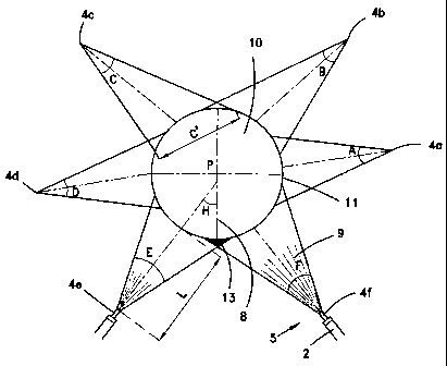
One embodiment of the present invention, which comprises a spraying apparatus
generally indicated by numeral 5, is illustrated in Fig. 1. After pipeline
section 10
of approximately 30 m is unearthed and securely supported, said pipeline
section
is raised 40-60 cm, so that the underside thereof may be impinged by a spray
9,
and maintenance of the entire pipeline periphery may therefore be effected.
Spraying apparatus 5 comprises stationary nozzles 4a-f, each of which is
positioned by means well known to those skilled in the art, at a different
angular
disposition with respect to center P of pipeline section 10. The maintenance
enhancing material is fed to each nozzle 4 through a corresponding conduit 2,
e.g.
a flexible tube, and is propelled by a fluid under sufficient pressure, such
as
water or air, so that the material may impinge periphery 11.
CA 02488450 2004-11-24
16247lH/03 #406100
_9.
The configuration and disposition of each nozzle 4, as well as the shortest
radial
distance L from a nozzle to periphery 11, are selected in order to ensure that
periphery 11 is completely sprayed, with an optimal utilization of the
material.
Due to the unique configuration and disposition of each nozzle, a different
spray
angle, e.g. spray angles A-F, as illustrated, may be generated from each
nozzle.
The circumferential distance of maintenance enhancing material impingement on
periphery 11 is also different for each nozzle, depending on the radial
distance L
from the nozzle to the pipeline periphery, e.g. circumferential distance C'
for
spray angle C. An optimal utilization of sprayed maintenance enhancing
material
is realized by reducing the overlapping of adjacent spray angles. For example,
spray angles E and F overlap at sector 13, and this overlapping ensures that
the
underside of pipeline section 10 will be completely sprayed by the maintenance
enhancing material.
It will be appreciated that the reduced distance to which pipeline section 10
needs to be raised, relative to a prior art pipeline maintenance apparatus, is
advantageously achieved as a result of the angular disposition of nozzles 4e
and
4f, which spray the underside of the pipeline section. In contrast to prior
art
spray devices which rotate about a pipeline section, such that the axis of
rotation
coincides with center P of the pipeline, necessitating sufficient clearance
under
the pipeline section for the rotation of the spray device around the pipeline
section, nozzles 4e and 4f are laterally spaced from the vertical centerline 8
of the
pipeline section. Consequently, the spray issuing from nozzles 4e and 4f
obliquely
impinge periphery 11, i.e. the angle H between shortest radial distance L and
vertical centerline 8 is greater than 20 degrees. Therefore pipeline section
10 can
be raised a shorter distance than with the use of prior art maintenance
devices,
since the nozzles that spray the underside of the pipeline section are
laterally
spaced from the vertical centerline of the pipeline section.
CA 02488450 2004-11-24
16247/H/03 #406100
- 10 -
Another embodiment of the present invention, which comprises a spraying
apparatus generally indicated by numeral 25, is illustrated in Figs. 2 and 3.
The
maintenance enhancing material is propelled to pipeline section 10 by means of
a
driven roller 30, on which a solution of the maintenance enhancing material is
dripped.
As shown in Fig. 2A, a low pressure solution 32 of maintenance enhancing
material is delivered by valve 33, e.g. a household faucet, onto solid roller
30.
Depending on the opening of valve 33, solution 32 may be dripped, or delivered
in
a fast flowing stream, onto the roller. Nozzle 34 with a predetermined spray
pattern is preferably attached to the outlet of valve 33, so that solution 32
will be
delivered across substantially the entire length of roller 30. Roller 30 is
driven by
motor 37, and therefore solution 32 is dispersed by the changing velocity
distribution of the air stream generated by the rotating roller, forming a
spray. A
spray 35 propelled by the driven roller is directed towards the pipeline
section.
When roller 30 is driven at a relatively low rotational speed, as shown in
Fig. 2B,
propelled spray 35 originally streams tangentially from roller 30 at contact
point
S of solution 32 with the roller and then descends by a curved flow onto
pipeline
section 10, due to the decreased influence of centrifugal force. Upon
increasing
the rotational speed of roller 30, propelled spray 35 streams tangentially
from
contact point S of the roller to impingement point I on the pipeline section,
as
shown in Fig. 2C, due to the increased influence of the centrifugal force
applied
by the rotating roller. Some of solution 32 adheres to roller 30 for a
fraction of a
rotation until being detached from the roller at point T, whereupon propelled
spray 35 streams tangentially from detachment point T until impinging the
pipeline section 10 at point J. Whereas the spray angle V of propelled spray
35
issuing from roller 30, which is defined as that angle subtended by a vertical
projection of the propelled solution generated by the spray means relative to
a
laterally extending horizontal line, is substantially equal to that of Fig.
2B, the
circumferential distance of impingement, i.e. between points I and J, is
CA 02488450 2004-11-24
1624?/H/03 #406100
- 11 -
considerably greater than that of Fig. 2B, due to the influence of the
increased
centrifugal force.
The spray pattern may be changed by adjusting contact point S of solution 32
with the roller. In Fig. 2D, contact point S, which does not coincide with the
vertical centerline 39, as in Fig. 2C, is diametrically opposite to the point
of the
roller that is closest to the pipeline section. Although the spray angle may
also
be V, the spray pattern is different than that illustrated in Fig. 2C. Whereas
the
propelled spray of Fig. 2C is horizontal at contact point S and then is
inclined at
point T, the propelled spray of Fig. 2D is inclined at contact point S and
then is
horizontal at detachment point T.
A typical arrangement of the rollers relative to a pipeline section is
illustrated in
Fig. 3A. Spraying apparatus 25 comprises enclosure 41 and four rollers 30a-d,
two of which are positioned on each lateral side of pipeline section 10. After
pipeline section 10 of approximately 30 m is unearthed and securely supported,
said pipeline section is raised 40-60 cm within enclosure 41. Enclosure 41 is
transportable along the length of the pipeline, and is of any suitable shape,
so as
to receive therein the pipeline section 10 and the plurality of rollers 30a-d.
Due to the configuration and position of each roller relative to the
longitudinal
axis P of pipeline section 10, maintenance enhancing material may be sprayed
around the entire periphery 11 of the pipeline section. Each roller 30 is
rotatingly
supported by a corresponding support 49, so that the roller is laterally
separated
from periphery 11 by a distance of M. Also, each roller 30 is positioned so
that its
axis N is vertically separated from axis P of the pipeline section by a
distance of
H, with axis N of rollers 30a and 30b being above axis P of pipeline section
10
and the axis of rollers 30c and 30d being below the axis of the pipeline
section.
The conduit (not shown), valve and nozzle through which a solution of
maintenance enhancing material is delivered onto a corresponding roller are
retained by the corresponding support 49. The rollers are accordingly
configured
CA 02488450 2004-11-24
16247/H/03 #406100
- 12 -
to produce a spray pattern of V degrees, wherein the propelled spray 35
tangentially streaming from the corresponding roller 30 is proximate to, but
does
not impinge, periphery 11 of the pipeline section, and a portion of propelled
spray
35 obliquely impinges periphery 11. Each roller is adapted for impinging
slightly
more than 90 degrees of periphery 11 by the spray issued therefrom.
The circumferential distance of impingement is dependent upon several
parameters: number of rollers 30, diameter of pipeline section 10, diameter of
each roller 30, distance M between the axis of a roller and periphery 11,
height H
between the axis of a roller and the axis of the pipeline section, the spray
angle
V, the spray pattern, the rotational speed of the rollers, and the density of
the
maintenance enhancing material that is propelled by the rollers. Thus the
circumferential distance of impingement can be controlled, in order to
minimize
the amount of adjacent propelled spray overlapping, by varying one or more of
the aforementioned parameters as a result of design constraints.
The arrangement illustrated in Fig. 3A is also suitable for propelling
maintenance enhancing material by means of stationary tubular casing
members, in each of which an impeller rotates. For purposes of clarity, the
placement of each casing may be identical to the illustrated rollers, whereby
to
produce a similar spray pattern.
As shown in Fig. 3B, each casing, which is generally indicated by numeral 26,
is
formed with a plurality of closed portions 27 and open portions 28. Each
peripheral closed portion 27 longitudinally extends throughout the entire
length
of the casing, and each open portion 28 is similarly formed throughout the
entire
length of the casing. The width of each open portion 28 is selected in such a
way,
so as to generate a predetermined spray pattern. The axis of rotation of
impeller
29 coincides with the longitudinal axis of casing 26. As maintenance enhancing
material is admitted to casing 26 by a plurality of inlet ports 31, which are
in
communication with the interior of the casing at predetermined locations, e.g.
CA 02488450 2004-11-24
16247/~i/03 #406100
13
along the underside of the casing or by a manifold 21 (shown in Fig. 3C), the
rotation of impeller 29 imparts a rotating motion to the maintenance enhancing
material. The maintenance enhancing material radially exits the casing via
open
portions 28 and accordingly impinges the pipeline section.
When the maintenance enhancing material is sand or another type of granular
abrasive material, pipeline section 10 may be sandblasted, in order to remove
corrosion formed on the periphery thereof. A prior art sandblasting apparatus
is
generally characterized by an inordinate waste of material. By employing
enclosure 41, granular abrasive material, particularly metallic or polymeric
granules, may be recaptured and recycled, thereby adding to the cost savings
that can be realized by sandblasting with the use of the present invention.
Fig. 4 illustrates a schematic diagram of an exemplary apparatus for
delivering
and recycling granular abrasive material. Pipeline section 10 is shown to be
raised above trench 51 with a sufficiently small clearance that allows for the
impingement of its periphery, e.g. by sandblasting, in accordance with the
present invention. Bottom 42 of enclosure 41 is placed between pipeline
section
and trench 51, while enclosure 41 is shaped such that it collects the
granules.
Enclosure 41, to which rollers 30 for spraying pipeline section 10 with
maintenance enhancing material are supported, is longitudinally conveyed along
the pipeline, in order to allow maintenance to be carried out on other
pipeline
sections. The drive means 45 for the enclosure, and consequently for the
rollers,
is rollingly supported by pipeline section 10, so that the enclosure may be
easily
and speedily conveyed to another pipeline section, upon command by an
operator.
Each conduit 55, through which maintenance enhancing material is delivered to
rollers 30, is flexible, e.g. a rubber hose, in order to allow for
longitudinal
displacement of the enclosure and of the rollers.
CA 02488450 2004-11-24
16247/H/03 #406100
- 14 -
Upon completion of a cycle during which abrasive granules are sprayed onto
pipeline section 10, as described hereinabove, the spent granules and debris,
such
as dirt, corrosion flakes and paint flakes, which were detached from the
pipeline
section during the sandblasting cycle, fall onto enclosure bottom 42 and are
gathered into area 52. Suction pump 57, or any other means to generate a
vacuum, entrains the spent granules and fallen debris in a gas stream flowing
through flexible suction line 53. Discharge from suction pump 57 is directed
to
filters 59, which filter contaminants from the flowing gas stream, and then to
centrifugal particulate separator 61, whereupon purified abrasive granules
fall
into recovery vessel 63. In order to replenish the supply of granules, new
granules may be fed into vessel 63. During commencement of a spray cycle, pump
65 delivers water or air under pressure, into which purified granules are
released
and entrained, through conduit 55. The solution of maintenance enhancing
material is delivered to each valve 33 (Fig. 2), for subsequent introduction
to each
roller 30, as described hereinabove. Suction pump 57, particulate separator
61,
and pump 65 are stationary, remaining outside of trench 51, during
displacement
of enclosure 41.
Fig. 5 schematically illustrates another embodiment of the invention, for
automated oblique spraying of the periphery of pipeline section 10, so that
material may be more efficiently utilized. Nozzle 71 issuing spray 69 of
maintenance enhancing material is rotated about vertical axis 73 by displacing
means 74, which generally is at least one electric motor, such that the spray
impinges periphery 11 in an essentially horizontal path 77. The length of path
77
that can be impinged by the nozzle is dependent on the total angular
displacement provided by displacing means. In order to ensure an essentially
horizontal path of impingement, the mechanism that imparts motion to nozzle 71
is structured such that the spray angle of nozzle 71 remains constant during
rotation, from one end of a path to the other end. The circumferential
distance of
impingement is a function of the distance of vertical axis 73 of rotation from
the
longitudinal axis of pipeline section 10 and of the spray pattern of nozzle
71.
CA 02488450 2004-11-24
16247/H/03 #406100
- 15 -
Upon completion of a horizontal path, displacement means 74 displaces nozzle
71
such that the subsequent path of impingement is adjacent to the previous path
of
impingement, thereby ensuring continuous impingement of maintenance
enhancing material throughout periphery 11. The number of displaceable nozzles
that are needed to ensure continuous impingement throughout the periphery
without having to be rotated underneath the pipeline section is dependent on
the
selected spray angle, the circumferential distance of impingement, the
pressure
of the fluid that propels the maintenance enhancing material to periphery 11,
and the maximum difference in height to which a nozzle may be displaced. A
controller (not shown) may control the operation of displacing means 74.
By employing a displaceable nozzle 71 for providing oblique spraying of
pipeline
section 10, compressed air may be the medium for propelling the spray. As
shown
in Fig. 6, upon commencement of a sandblasting cycle, clean, compressed air is
forced from compressor 66 and then to dehumidifier 67. Dehumidified
compressed air flows through conduit 55, into which purified granules are
released from vessel 63 and entrained by the compressed air, and then the
entrained granules are delivered to nozzles 71. The recycling of granules is
similar to the aforementioned description in relation to Fig. 4.
Figs. 7A and 7B illustrate an exemplary mechanism which allows the spray angle
of a nozzle to remain constant during rotation, from one end of an impingement
path to the other end. The illustrated mechanism utilizes gimbal joint 80,
which
allows gimbal 91, and consequently nozzle 71, to be rotated about two mutually
perpendicular axes. Maintenance enhancing material is delivered through
conduit 55, adapter 79 and nozzle 71, from which it is sprayed onto the
periphery
of a pipeline section. Nozzle 71 is keyed, or is rigidly affixed by any other
suitable
means, to rotor 82. Rotor 82 in turn is keyed to diametrically opposite rods
85
and 86 with a common axis 83, which are coupled to the rotor and to
corresponding shafts, one of which is driven by displacing means 74 (Fig. 5).
CA 02488450 2004-11-24
16247/H/03 #406100
- 16 -
Annular ring 89 connects rotor 82 to gimbal 91, and consequently rotor 82 and
gimbal 91 are displaceable in unison.
The top and bottom of gimbal 91 is fastened to a corresponding flange 93, each
of
which is keyed to substantially vertical shafts 95A and 95B, respectively,
having
a common axis 96, which is perpendicular to axis 83. The axis of gimbal 91 is
coincident with the intersection of axes 83 and 96. As a spray is being issued
from nozzle 71 during the course of an impingement path, a substantially
vertical
shaft 95 is rotated by displacing means 74, causing gimbal 91, rotor 82 and
nozzle 71 to be rotated a predetermined angular displacement about axis 96
which generates an impingement path having a desired length. During rotation
about axis 96, rods 85 and 86 are locked, preferably by a controller. Upon
completion of an impingement path, shafts 95A and 95B are locked and rods 85
and 86 are unlocked. Another spray angle may be selected by rotating rotor
about
axis 83, at a sufficient angular displacement that can generate another
impingement path that is adjacent to, but does not overlap to a large extent,
the
previously generated impingement path.
Fig. 8 illustrates another exemplary mechanism which allows the spray angle of
a nozzle during generation of an impingement path. Nozzle 71 is pivotable
about
a shaft, or a pair of shafts, having an axis that is perpendicular to vertical
axis
105, about which assembly 110 housing the nozzle, rotates. Nozzle 71 may be
secured to assembly 110, to ensure that the spray angle will be constant
during
the rotation of assembly about axis 105.
Similarly, the nozzle may be displaceable by means of a ball-and-socket joint,
or
by any other suitable mechanism.
The aforementioned apparatus is suitable for the maintenance of any tubular
member, for various other applications such as the cleaning of pipes at a
power
plant or of transcontinental cables buried underwater. It will be appreciated
that
CA 02488450 2004-11-24
1624?/H/03 #406100
- 17 -
the spray angle during generation of an impingement path may be variable, if
so
desired. Similarly, the tubular member may not necessarily be horizontal
during
maintenance and the axis about which the nozzle housing rotates may be
inclined.
CA 02488450 2004-11-24
16247/H/03 #406100
- 18 -
Example 1
Corrosion Removal
Fig. 9 illustrates an apparatus that was used to remove corrosion from the
outer
surface of a buried pipeline having an inner diameter of 107 cm, when oil was
flowing therethrough.
A trench having a width of 3 m was dug, and a pipeline section 10 of 1000 m
was
raised a height of 50 cm. The pipeline section was supported by two supports
20,
spaced 30 m from each other. Pipeline section 10 passed through opposite walls
of enclosure 41.
Metallic granules, which were delivered through flexible conduit 55 to two
displaceable nozzles 71, were entrained by compressed air. Each nozzle 71 was
disposed at a different lateral side of pipeline section 10. A gimbal joint 80
mounted on a wall of enclosure 41 was used to allow each nozzle 71 to be
rotated
about two mutually perpendicular axes, as indicated by the arrows. Motor 107
drove a substantially vertical shaft, so that nozzle 71, which was directed at
the
periphery of pipeline section 10, generated an essentially horizontal path of
impingement, and corrosion was removed from the periphery at a rate of 0.4 m
per minute. After completing a first impingement path, motor 108 rotated
gimbal
joint 80, in order to generate a second impingement path. A plurality of
impingement paths were generated by each nozzle, in order remove corrosion
from the entire periphery of the pipeline section. The operation of motors 107
and
108 was synchronized by a suitable controller.
Spent granules fell onto enclosure bottom 42 and were gathered into area 52. A
suction pump generated a vacuum, urging the spent granules and fallen debris
through flexible suction line 53. The spent granules were recycled, and were
reused for 100 sandblasting cycles.
CA 02488450 2004-11-24
16247/H/03 #406100
- 19 -
After corrosion was removed from the entire periphery of pipeline section 10,
drive means 45, which was rollingly supported by pipeline section 10 on the
top
thereof, was operated upon command by an operator. The drive means was
connected to enclosure 41, and the enclosure was longitudinally advanced to
allow another pipeline section to be cleaned.
Example 2
Application of Paint
Fig. 10 illustrates an apparatus generally designated by numeral 110 that was
used to apply a uniform coating of paint onto the outer surface of a buried
pipeline having an inner diameter of 107 cm, when oil was flowing
therethrough.
A trench 51 having a width of 3 m was dug, and a pipeline section 10 was
raised
a height of 50 cm. The pipeline section was supported by two supports spaced
30
m from each other.
Epoxy paint was entrained by compressed air, such that paint was delivered
through tubular conduit 125 to nozzle 121 fixed at the distal end of the
conduit.
Conduit 125 was rotatably mounted within sheathing 131 in such a way that
nozzle 121 was always directed to the periphery of pipeline section 10.
Sheathing
131 in turn was rotated about the axis of pipeline section 10 a total angular
displacement of 280 degrees, whereby nozzle 121, at the completion of an
angular
displacement, obliquely sprayed paint at the underside of the pipeline
section.
Apparatus 110 was adapted to be longitudinally displaceable. Apparatus 110 was
structured by a frame that comprised a plurality of interconnected
longitudinally
extending bars 115, laterally extending bars 117, vertically extending bars
119
and inclined bars 120. These bars were arranged such that the frame was
symmetrical with respect to the axis of the pipeline section. Two concave
rollers
135 having a variable cross-section were used to longitudinally displace the
apparatus, wherein one of the rollers was an idler roller. The cross-section
of
CA 02488450 2004-11-24
1624?/H/03 #406100
rollers 135 varied in such a way that the resulting curvature was
substantially
equal to that of pipeline section 10, so that the rollers were placed on top
of the
pipeline section, with the axis of each roller being perpendicular to the axis
of the
pipeline section. The axles 136 of each roller 135 were rotatingly mounted in
a
corresponding ring hanger 137 affixed to a longitudinally extending bar 115,
except for one axle of the driven roller which was driven by motor 138. Motor
138
was mounted on the frame of the apparatus, and when operated, the driven and
idler rollers rotated, frictionally contacting the periphery of the pipeline
section
and thereby allowing apparatus 110 to be longitudinally displaced.
After being displaced to a desired pipeline section, the frame was immobilized
by
legs 126 that were anchored to trench 51. Each leg 126 was normally retained
in
a normally retracted disposition within a corresponding hollow longitudinally
extending bar 119. Upon actuation of each hydraulic cylinder 128 that was
mounted on a corresponding longitudinally extending bar 115, each
corresponding leg 126 was downwardly displaced to trench 51 by means of the
corresponding cylinder 128, and the frame was thereby immobilized.
Sheathing 131 was rotated about the axis of pipeline section by means of a
pair
of arcuate stabilizer members 141 and two pairs of arcuate rotatable members
147, with the pair of stabilizer members interposed between each pair of
rotatable members. Stabilizer members 141 and rotatable members 147 were
concentric with the axis of pipeline section 10, while the width of a
rotatable
member 147 was less than that of a stabilizer member 141. Guide rollers 171
and
172, which were rotatably mounted on stabilizer members 141, supported and
radially restrained rotatable members 147. Since stabilizer members 141 were
rigidly connected to the frame of the apparatus, members 147 were rotated
relative to the stabilizer members when a torque was applied to the rotatable
members, following immobilization of the frame.
CA 02488450 2004-11-24
16247/H/03 #406100
- 21 -
Torque was transmitted to rotatable members 147 by a chain drive. To allow for
a high rate of torque transmission and a compact balanced construction during
rotation, each inner rotatable member 147 was made from two arcuate plates,
between which a toothed transmission device was mounted. Four rods 161
connecting the two stabilizer members 141 were rotatably mounted
therebetween, with the circumferential location of two rods being symmetrical
about a vertical centerline of the pipeline section to that of the other two
rods. A
sprocket 163 was mounted on each rod 161 between the two stabilizer members
141, and an endless roller chain (not shown) was wrapped about each sprocket
163 and about sprocket 158 mounted on the output shaft of the motor 150.
Another sprocket 164 was mounted on each rod 161, on the outer side of each
stabilizer member 141. Each sprocket 164 was engageable with the transmission
device that was mounted between the two plates of the inner rotatable member.
As motor 150 was operated, sprocket 158 mounted on the output shaft of the
motor was rotated, driving sprocket 164 mounted on the outer side of each
stabilizer member 141 by means of the roller chain, and thereby causing
rotatable members 147 to rotate. The angular displacement of the rotatable
members was limited by abutment plates 175 that were affixed at the two
circumferential ends, respectively, of a rotatable member. An abutment plate
175
was wider than a rotatable member 147, and therefore contacted a
longitudinally
extending rod 115 when the rotatable members were rotated beyond their
rotational limit, thereby preventing additional rotation. Rotatable members
147
did not rotate in a reverse direction when motor 150 was deactivated due to
the
engagement of sprockets 164 with the transmission device integral with the
rotatable members.
Sheathing 131 was connected to each pair of rotatable members 147 by
triangular brace 155, at the circumferential middle of the rotatable members.
The short end of each brace 155 was integrally formed with a ring support 156,
into which sheathing 131 was inserted. As a result, sheathing 131 and
rotatable
members 147 rotated in unison. Motor 169 which caused conduit 125 to rotate
CA 02488450 2004-11-24
16247/H/03 #406100
- 22 -
was carried by the outer rotatable member, and therefore conduit 125 could
rotate about the axis of sheathing 131 concurrently with the rotation of
rotatable
members 147 about the axis of pipeline section 10.
A controller (not shown) synchronized the operation of motors 150 and 169 so
that nozzle 121 was always directed to the periphery of pipeline section 10,
regardless of the angular position of sheathing 131. The controller also
controlled
the operation of a hydraulic actuator (not shown) which caused conduit 125 to
retract into sheathing 131 at a fixed rate upon cessation of the rotation of
rotatable members 147, whereby nozzle 121 generated an elongated impingement
path which provided a uniform paint coating onto the periphery of the pipeline
section. At the completion of the impingement path, conduit 125 telescoped to
its
maximum length and rotatable members 147 rotated to another angular position,
such that the paint coating of the newly generated impingement path was
continuous with, and having the same thickness as, the previously generated
impingement path.
Motor 150 transmitted torque to rotating members 147. Nozzle 121, which was
directed at the periphery of pipeline section 10, generated an elongated path
of
impingement, and paint was applied onto the periphery in such a way that a
uniform thickness of paint was applied.
While some embodiments of the invention have been described by way of
illustration, it will be apparent that the invention can be carried into
practice
with many modifications, variations and adaptations, and with the use of
numerous equivalents or alternative solutions that are within the scope of
persons skilled in the art, without departing from the spirit of the invention
or
exceeding the scope of the claims.