Sélection de la langue

Search

Sommaire du brevet 2489079 

Énoncé de désistement de responsabilité concernant l'information provenant de tiers

Une partie des informations de ce site Web a été fournie par des sources externes. Le gouvernement du Canada n'assume aucune responsabilité concernant la précision, l'actualité ou la fiabilité des informations fournies par les sources externes. Les utilisateurs qui désirent employer cette information devraient consulter directement la source des informations. Le contenu fourni par les sources externes n'est pas assujetti aux exigences sur les langues officielles, la protection des renseignements personnels et l'accessibilité.

Disponibilité de l'Abrégé et des Revendications

L'apparition de différences dans le texte et l'image des Revendications et de l'Abrégé dépend du moment auquel le document est publié. Les textes des Revendications et de l'Abrégé sont affichés :

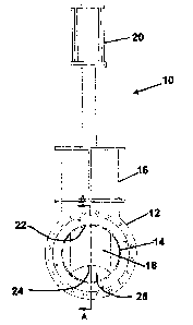
  • lorsque la demande peut être examinée par le public;
  • lorsque le brevet est émis (délivrance).
(12) Brevet: (11) CA 2489079
(54) Titre français: ROBINET-VANNE A GUILLOTINE
(54) Titre anglais: KNIFE GATE VALVE
Statut: Accordé et délivré
Données bibliographiques
Abrégés

Abrégé français

Valve servant à régler le débit d'une substance. Le corps de la valve comprend un alésage, un guide fixé au corps de la valve, une vanne mobile glissant dans le guide et se prolongeant dans l'alésage, de même qu'un actionneur pour la vanne. L'alésage du corps de la vanne est profilé à l'endroit ou la vanne pénètre dans l'alésage et celle-ci est munie d'un bord d'attaque concave dont le profil s'adapte à celui de l'alésage. La valve peut être utilisée pour régler un débit.


Abrégé anglais

A valve for controlling the flow of materials is provided. The valve has a valve body having a bore, a guide attached to the valve body, a gate movable within the guide into and out of the bore, and an actuator for the gate, the bore of the valve body having a profile where the gate enters the bore, and the gate having a concave leading edge conforming to a profile of the bore. The valve may be us ed in throttling applications.

Revendications

Note : Les revendications sont présentées dans la langue officielle dans laquelle elles ont été soumises.


THE EMBODIMENTS OF THE INVENTION IN WHICH AN EXCLUSIVE PROPERTY OR
PRIVILEGE IS CLAIMED ARE DEFINED AS FOLLOWS:
1. A valve comprising:
a valve body having a bore;
a guide attached to the valve body;
a gate movable within the guide into the bore from a retracted position and
out of the
bore into the retracted position;
an actuator for the gate;
the bore of the valve body having sides and a bore width between the sides,
and the
bore having a profile where the gate enters the bore;
the gate having a concave leading edge conforming to the profile of the bore,
the
concave leading edge of the gate being flush with the profile of the bore
where the
gate enters the bore to eliminate exposed chest area when the gate is in the
retracted
position; and the gate having a gate width less than the bore width to produce
gaps
between the sides of the bore and the gate when the gate is extended into the
bore.
2. The valve of claim 1, where the gate is a knife gate.
3. The valve of claim 1 where the valve body further comprises retainer rings
and a valve
body bore liner.
4. The valve of claim 3 where the retainer rings and valve body bore liner are
replaceable.
5. The valve of claim 1, where the valve body further comprises an insert, the
insert creating
an obstruction in the bore.

6
6. The valve of claim 5, where the insert is V-shaped.
7. The valve of claim 1 in which:
the bore is circular and has a diameter;
the knife gate has parallel sides separated by the gate width;
the gate width is less than the diameter of the bore; and
the leading edge of the gate has a leading edge diameter equal to the diameter
of the bore.
8. A knife gate valve comprising:
a valve body having a bore;
a guide attached to the valve body;
a gate movable within the guide into the bore from a retracted position and
out of the
bore into the retracted position;
an actuator for the gate;
the bore of the valve body having sides and a bore width between the sides,
and the
bore having a profile where the gate enters the bore;
the gate having a recessed leading edge conforming to the profile of the bore,
the
recessed leading edge of the gate being flush with the profile of the bore
where the
gate enters the bore to eliminate exposed chest area when the gate is in the
retracted
position; and the gate having a gate width less than the bore width to produce
gaps
between the sides of the bore and the gate when the gate is extended into the
bore.
9. The knife gate valve of claim 8 in which:
the bore is circular and has a diameter;
the knife gate has parallel sides separated by the gate width;
the gate width is less than the diameter of the bore; and
the leading edge of the gate has a leading edge diameter equal to the diameter
of the bore.

Description

Note : Les descriptions sont présentées dans la langue officielle dans laquelle elles ont été soumises.

CA 02489079 2010-02-05
KNIFE GATE VALVE
BACKGROUND OF THE INVENTION
001 Gate valves are commonly used in the mining, pulp and paper, and food
handling
industries, among others. As known in the art, the gate moves linearly,
perpendicular to the
direction of flow. Typically, gate valves are used in a fully opened or fully
closed position, and
generally considered not suitable for throttling applications. In order to
seat properly when fully
closed, the typical gate valve is shaped to occupy all or substantially all of
the bore. While this
provides for robust sealing, the shape of the gate also has its disadvantages.
002 In a fully open position, areas within the bonnet or guide of a typical
gate valve, known
in the art as the chest area, may be exposed to flowing materials. When used
in higher flow
applications, this flow can have a detrimental effect on the integrity of the
valve. Materials can
also get clogged within the chest area of the valve body and the guide. Even
if the chest area
could be suitably sealed off, the traditional shape of the gate may create
flow characteristics not
desirable for throttling applications.
SUMMARY OF THE INVENTION
003 The present invention provides a gate valve for use in throttling
applications.
004 The gate valve in one embodiment comprises a valve body having a bore, a
guide
attached to the valve body, a gate movable within the guide into the bore from
a retracted
position and out of the bore into the retracted position; an actuator for the
gate; the bore of the
valve body having sides and a bore width between the sides, and the bore
having a profile where
the gate enters the bore; the gate having a concave leading edge conforming to
the profile of the
bore, the concave leading edge of the gate being flush with the profile of the
bore where the gate
enters the bore to eliminate exposed chest area when the gate is in the
retracted position; and the
gate having a gate width less than the bore width to produce gaps between the
sides of the bore
and the gate when the gate is extended into the bore.

CA 02489079 2004-12-21
2
BRIEF DESCRIPTION OF THE FIGURES
005 Preferred embodiments of the invention will now be described with
reference to the
figures, in which like reference characters denote like elements, by way of
example, and in
which:
Fig. 1 is a front view of one embodiment of the valve;
Fig. 2 is a cross-section of the valve taken along line A of Fig. 1;
Fig. 3 is a perspective view of the valve in Fig. 1;
Fig. 4 is a front view of an alternative embodiment of the valve;
Fig. 5 is a rear view of the valve in Fig. 4;
Fig. 6 is a cross-section of the valve taken along line A of Fig. 4; and
Fig. 7 is a perspective view of tll valve ofFig. 4..
DETAILED DESCRIPTION OF PREFERRED EMBODIMENTS
006 In the claims, the word "comprising" is used in its inclusive sense and
does not
exclude other elements being present. The indefinite article "a" before a
claim feature does
not exclude more than one of the feature being present. The phrase "concave
leading edge"
refers to any shape of the leading edge such that if a straight line were
drawn from one side of
the end of the gate to the other side of the end of the gate, no part of the
leading edge would
touch any part of that line, and comprises any edge forming a recess.
007 Referring to Figs. 1 to 3, a valve 10 has a valve body 12 having a bore
14, a guide 16
attached to the valve body 12, a gate 18 movable within the guide 16 into and
out of the bore
14, and an actuator 20 for the gate 18. In a preferred embodiment, the bore 14
is circular.
The bore 14 has a profile 22, and the gate 18 has a concave leading edge 24
that conforms to
the profile 20 of the bore 14. The leading edge 24 is shaped such that when
the gate 18 is in a
fully open position, the leading edge 24 of the gate 18 is completely flush
with the profile 22
of the bore 14. This results in a complete elimination of any chest area
within the valve body
12 or the guide 16.

CA 02489079 2004-12-21
3
008 The valve gate 18 may be made of any suitable material for the application
The valve
gate may also be replaceable. In a preferred embodiment, the gate 18 is a
knife gate, but any
type of gate capable of linear movement perpendicular to the direction of flow
through the
valve 10 may be used. The gate 18 is movable incrementally between a fully
open position
where the gate 18 is retracted within the guide 16 and a fully lowered
position where the gate
18 acts in a throttling fashion within the bore 14, creating an obstruction
around which the
material flows. In a fully lowered position, the gate 18 will not seat in a
fashion causing a
total obstruction within the bore. The shape of the gate 18 inherently
requires that a gap 26
exist in the bore 14 at least between the leading edge 24 of the gate 18 and
the side of the bore
14 opposite the profile 22. The gap 26 may also occur between the sides of the
gate 18 and
the sides of the bore 14.
009 The valve body 12 may be unitary in construction, or it may have
replaceable parts.
The valve body 12 may have replaceable retainer rings 28. The retainer rings
28 may be
made of any suitable material for the application. The retainer rings 28 would
be installed in
conventional fashion using seals known in the art. The valve body 12 may also
have a
replaceable valve body bore liner 30 made of any suitable material for the
application
010 The actuator 20 may be of any type suitable for the purpose, including
handwheels,
chainwheels, bevel gears, levers, cylinders and electric motors. In a
preferred embodiment,
the actuator 20 uses a cylinder.
Ol l In an alternative embodiment, as shown in Figs. 4 to 7, the valve 40
incorporates a V-
shape in the valve body 12. The V-shape may be formed with the use of a V-
shaped insert 42.
All other parts are the same between the valve 10 and the valve 40. The V-
shaped insert 42
may be made of any suitable material for the application. The V-shaped insert
42 may be
replaceable. When the gate 18 of valve 40 is raised in a fully open position,
the V-shaped
insert 42 creates an initial obstruction which constricts the flow of material
passing through
the bore 14. As the gate 18 is lowered, the V-shaped insert 42 prevents
material from flowing

CA 02489079 2004-12-21
4
around the sides of gate 18. Also, the gap 26 between the side of the bore 14
opposite the
profile 22 and the leading edge 24 of the gate 18 is greatly reduced.
012 It should be understood that the V-shaped bore liner may be some other
shape than a
V, such as a modified V-shape, a [shape, a diamond, a rectangle, semi-circles
with parallel
sides, or crescent-shaped, depending on the degree of initial obstruction and
final obstruction
desired and the flow characteristics desired within the bore 14 of the valve
40.
013 Immaterial modifications may be made to the embodiments of the invention
described
here without departing from the invention.

Dessin représentatif
Une figure unique qui représente un dessin illustrant l'invention.
États administratifs

2024-08-01 : Dans le cadre de la transition vers les Brevets de nouvelle génération (BNG), la base de données sur les brevets canadiens (BDBC) contient désormais un Historique d'événement plus détaillé, qui reproduit le Journal des événements de notre nouvelle solution interne.

Veuillez noter que les événements débutant par « Inactive : » se réfèrent à des événements qui ne sont plus utilisés dans notre nouvelle solution interne.

Pour une meilleure compréhension de l'état de la demande ou brevet qui figure sur cette page, la rubrique Mise en garde , et les descriptions de Brevet , Historique d'événement , Taxes périodiques et Historique des paiements devraient être consultées.

Historique d'événement

Description Date
Exigences relatives à la révocation de la nomination d'un agent - jugée conforme 2020-04-22
Exigences relatives à la nomination d'un agent - jugée conforme 2020-04-22
Représentant commun nommé 2019-10-30
Accordé par délivrance 2010-10-19
Inactive : Page couverture publiée 2010-10-18
Inactive : Taxe finale reçue 2010-08-09
Préoctroi 2010-08-09
Lettre envoyée 2010-06-07
Un avis d'acceptation est envoyé 2010-06-07
Inactive : Approuvée aux fins d'acceptation (AFA) 2010-05-13
Modification reçue - modification volontaire 2010-02-05
Inactive : Dem. de l'examinateur par.30(2) Règles 2009-08-06
Lettre envoyée 2008-02-19
Requête visant une déclaration du statut de petite entité reçue 2008-01-21
Lettre envoyée 2008-01-17
Inactive : Correspondance - Transfert 2007-12-20
Exigences pour une requête d'examen - jugée conforme 2007-12-20
Requête visant une déclaration du statut de petite entité reçue 2007-12-20
Toutes les exigences pour l'examen - jugée conforme 2007-12-20
Déclaration du statut de petite entité jugée conforme 2007-12-20
Requête visant une déclaration du statut de petite entité reçue 2007-12-20
Requête d'examen reçue 2007-12-20
Demande publiée (accessible au public) 2006-06-21
Inactive : Page couverture publiée 2006-06-20
Inactive : Lettre officielle 2006-05-09
Inactive : Transfert individuel 2006-04-21
Inactive : CIB en 1re position 2005-03-11
Inactive : Certificat de dépôt - Sans RE (Anglais) 2005-01-19
Exigences de dépôt - jugé conforme 2005-01-19
Demande reçue - nationale ordinaire 2005-01-19

Historique d'abandonnement

Il n'y a pas d'historique d'abandonnement

Taxes périodiques

Le dernier paiement a été reçu le 2009-12-17

Avis : Si le paiement en totalité n'a pas été reçu au plus tard à la date indiquée, une taxe supplémentaire peut être imposée, soit une des taxes suivantes :

  • taxe de rétablissement ;
  • taxe pour paiement en souffrance ; ou
  • taxe additionnelle pour le renversement d'une péremption réputée.

Veuillez vous référer à la page web des taxes sur les brevets de l'OPIC pour voir tous les montants actuels des taxes.

Historique des taxes

Type de taxes Anniversaire Échéance Date payée
Taxe pour le dépôt - petite 2004-12-21
TM (demande, 2e anniv.) - petite 02 2006-12-21 2006-12-06
Enregistrement d'un document 2007-12-20
TM (demande, 3e anniv.) - petite 03 2007-12-21 2007-12-20
Requête d'examen - petite 2007-12-20
TM (demande, 4e anniv.) - petite 04 2008-12-22 2008-10-24
TM (demande, 5e anniv.) - petite 05 2009-12-21 2009-12-17
Taxe finale - petite 2010-08-09
TM (brevet, 6e anniv.) - petite 2010-12-21 2010-10-21
TM (brevet, 7e anniv.) - petite 2011-12-21 2011-12-13
TM (brevet, 8e anniv.) - petite 2012-12-21 2012-12-06
TM (brevet, 9e anniv.) - petite 2013-12-23 2013-12-18
TM (brevet, 10e anniv.) - petite 2014-12-22 2014-10-15
TM (brevet, 11e anniv.) - petite 2015-12-21 2015-10-02
TM (brevet, 12e anniv.) - petite 2016-12-21 2016-10-11
TM (brevet, 13e anniv.) - petite 2017-12-21 2017-11-24
TM (brevet, 14e anniv.) - petite 2018-12-21 2018-10-31
TM (brevet, 15e anniv.) - petite 2019-12-23 2019-11-22
TM (brevet, 16e anniv.) - petite 2020-12-21 2020-12-02
TM (brevet, 17e anniv.) - petite 2021-12-21 2021-10-15
TM (brevet, 18e anniv.) - petite 2022-12-21 2022-10-13
TM (brevet, 19e anniv.) - petite 2023-12-21 2023-10-30
Titulaires au dossier

Les titulaires actuels et antérieures au dossier sont affichés en ordre alphabétique.

Titulaires actuels au dossier
SUMMIT VALVE AND CONTROLS INC.
Titulaires antérieures au dossier
MICHEL LEROUX
Les propriétaires antérieurs qui ne figurent pas dans la liste des « Propriétaires au dossier » apparaîtront dans d'autres documents au dossier.
Documents

Pour visionner les fichiers sélectionnés, entrer le code reCAPTCHA :


Pour visualiser une image, cliquer sur un lien dans la colonne description du document. Pour télécharger l'image (les images), cliquer l'une ou plusieurs cases à cocher dans la première colonne et ensuite cliquer sur le bouton "Télécharger sélection en format PDF (archive Zip)" ou le bouton "Télécharger sélection (en un fichier PDF fusionné)".

Liste des documents de brevet publiés et non publiés sur la BDBC .

Si vous avez des difficultés à accéder au contenu, veuillez communiquer avec le Centre de services à la clientèle au 1-866-997-1936, ou envoyer un courriel au Centre de service à la clientèle de l'OPIC.


Description du
Document 
Date
(aaaa-mm-jj) 
Nombre de pages   Taille de l'image (Ko) 
Description 2004-12-21 4 202
Abrégé 2004-12-21 1 19
Dessins 2004-12-21 3 97
Revendications 2004-12-21 2 48
Dessin représentatif 2006-05-25 1 7
Page couverture 2006-06-09 1 29
Description 2010-02-05 4 195
Revendications 2010-02-05 2 62
Page couverture 2010-09-29 1 30
Certificat de dépôt (anglais) 2005-01-19 1 158
Rappel de taxe de maintien due 2006-08-22 1 110
Courtoisie - Certificat d'enregistrement (document(s) connexe(s)) 2008-01-17 1 105
Accusé de réception de la requête d'examen 2008-02-19 1 177
Avis du commissaire - Demande jugée acceptable 2010-06-07 1 166
Paiement de taxe périodique 2023-10-30 1 26
Taxes 2011-12-13 1 155
Taxes 2012-12-06 1 155
Paiement de taxe périodique 2018-10-31 1 24
Correspondance 2005-01-19 1 72
Correspondance 2006-05-09 1 8
Correspondance 2006-05-09 1 19
Correspondance 2006-08-22 1 38
Taxes 2006-12-06 1 26
Taxes 2007-12-20 3 65
Correspondance 2007-12-20 3 66
Correspondance 2008-01-17 1 9
Correspondance 2008-02-19 1 85
Correspondance 2007-01-17 1 21
Correspondance 2007-12-20 3 81
Correspondance 2008-01-21 4 93
Taxes 2008-10-24 1 28
Taxes 2009-12-17 1 26
Correspondance 2010-06-07 1 88
Correspondance 2010-08-09 1 28
Taxes 2010-10-21 1 199
Taxes 2013-12-18 1 23
Taxes 2014-10-15 1 24
Taxes 2015-10-02 1 24
Taxes 2016-10-11 1 25
Paiement de taxe périodique 2017-11-24 1 24
Paiement de taxe périodique 2019-11-22 1 25
Paiement de taxe périodique 2020-12-02 1 25
Paiement de taxe périodique 2021-10-15 1 25
Paiement de taxe périodique 2022-10-13 1 26