Note : Les descriptions sont présentées dans la langue officielle dans laquelle elles ont été soumises.
a , CA 02489170 2004-12-O1
Atty. Dkt. No.: 084158-015
PRESTRESSED OR POST TENSION COMPOSITE
STRUCTURAL SYSTEM
CROSS-REFERENCE TO RELATED PATENT APPLICATIONS
[0001 ] None.
BACKGROUND OF THE INVENTION
[0002] The present invention relates to the improved construction of bridges,
roads, sidewalks, and buildings. More particularly, the present invention
relates to an
improved unfilled grating composite with a reinforced, prestressed or post-
tensioned
concrete slab. The invention also relates to a method of making an improved
unfilled
grating composite with a reinforced, prestressed or post-tensioned concrete
slab.
[00031 The widespread deterioration of road structures, specifically bridges,
has
been acknowledged as a critical problem in our Nation's transportation system.
The
Federal Government considers hundreds of thousands of bridges structurally
deficient
or functionally obsolete. A major factor contributing to such classifications
is a
deteriorated bridge deck (the roadway surface). The life span of the bridge
deck
averages only one half the service life of the other components of the average
bridge.
[0004] The rehabilitation and re-decking of existing deficient structures, as
well
as deck designs for new structures, must account for many factors affecting
bridge
construction and rehabilitation. These factors include increased usage,
increased
loading, reduced maintenance, increased use of salts for snow and ice
mitigation, and
the need for lower costs, lighter weight, and more efficient construction
techniques.
[0005] In the mid-1980's, the first patents issued on a new grid deck designed
to
solve the problems of prior designs. This new grid deck is referred to as an
ExodermicTM deck. An ExodermicTM deck is comprised of a reinforced concrete
slab
on top of, and composite with, an unfilled steel grid. This maximizes the use
of the
compressive strength of concrete and the tensile strength of steel. Horizontal
shear
-1-
001.1530687.1
CA 02489170 2004-12-O1
Atty. Dkt. No.: 08415 8-013 5
transfer is developed through the partial embedment in the concrete of the top
portion
of the main bars The following U.S. patents all relate to various features of
an
ExodermicTM deck: U.S. Pat. Nos. 4,531,857, 4,531,859, 4,780,021, 4,865,486,
5,509,243, and 5,664,378. These patents all disclose unfilled grid decks
composite
with reinforced concrete slabs.
[0006] Historically, the ExodermicTM deck evolved from traditional concrete
filled grids. The innovation of these decks was to move the concrete from
within the
grid to the top of the grid in order to make more efficient use of the two
components.
Putting the concrete on top also allowed the use of reinforcing steel in the
slab to
significantly increase the negative moment capacity of the design, and moved
the
neutral axis of the section close to the fabrication welds of the grid. A
shear
connecting mechanism was required between the grid and the slab to make the
two
components into a composite structure. This was originally provided by using a
grid
having main bearing bars, distribution bars, and tertiary bars. Welded to the
tertiary
bars were short, 112" diameter studs which served to transfer shear and
maintain a
mechanical connection between components.
[00071 An Exodermic deck typically weighs 35% to 50% less than a reinforced
concrete deck that would be specified for the same span. Reducing the dead
load on a
structure can often mean increasing the live load rating. The efficient use of
materials
in an Exodermic deck means the deck can be much lighter without sacrificing
strength, stiffness, ride quality, or expected life.
[0008] In a revised design of an Exodermic deck, the tertiary bars were
eliminated, which saved weight, cost, and fabrication problems. Thus, the
grating
included only main bearing bars and distribution bars. In this revised design,
since
there were no tertiary bars, the function of the shear transfer studs on the
tertiary bars
was taken over by extension of the main bars of the grid 1" into the slab.
Holes were
punched in the top 1" of the main bars, to aid in the engagement of the bars
with the
concrete.
[0009] In the revised design, the main bearing bars and the distribution bars
are
interconnected into a grating, which requires extensive fabrication. In ordex
to
assemble the grating, the main bearing bars have had fabrication holes punched
into
-2-
001.1530687.1
CA 02489170 2004-12-O1
Atty. Dkt. No.: 084158-0135
them. The distribution bars are inserted through the fabrication holes and
welded to
the main bearing bars at every intersection, to thereby form the grating
structure.
[0010] Welding the main bearing bars and the distribution bars can induce
distortion in the steel grating. Manufacturers may need to construct the steel
gratings
for unfilled grid decks composite with reinforced concrete slabs using purpose
built
jigs and a specialized welding pattern to minimize such distortion.
[0011 ] Because most unfilled grid decks composite with reinforced concrete
slabs
are constructed in environments where corrosion of the embedded and exposed
steel
is likely unless preventive measures are taken, the steel grating component is
generally protected by hot-dip galvanizing. Warping of steel gratings due to
hot-dip
galvanizing is a substantial problem for all types of steel grating decks,
including
unfilled grid decks composite with reinforced concrete slabs. Warpage is due
to a
combination of stress relieving of the welds in the 850°F molten zinc
and by
differential heating and cooling of the large grating panels as they are
dipped in and
then removed from the galvanizing kettles. This warping regularly produces
grating
panels that must either be reworked in the factory, or pushed and/or pulled
into proper
shape in the precast plant or in the field.
[0012] To eliminate some of these fabrication problems, U.S. Patent No.
5,664,378 discloses a fizrther variation of the Exodermic deck .This further
revision
eliminates not only the tertiary bars, but it also eliminates the distribution
bars of the
base grid component. Thus, this variation uses a base grating of only main
bearing
bars. It was thought that this would further reduce costs, weight, and
fabrication
issues. While it did achieve these objectives, it was found that eliminating
the
distribution bars created significant problems with shear transfer and
durability.
[0013] The present invention has eliminated or minimized the problems that
result
when the distribution bars are eliminated. The present invention has found
that using
prestressed or post-tensioned concrete allows the distribution bars of the
grid to be
eliminated, yet still maintain effective shear transfer and durability in a
grating that is
made from only main bearing bars.
-3-
0o~.~5soss~.~
CA 02489170 2004-12-O1
Atty. Dkt. No.: 084158-0135
SUM~~rIARY OF THE INVENTION
[00141 This invention provides a new unfilled grating composite with
reinforced
concrete slab design. The present invention uses a grating of only main
bearing bars.
The grating does not use distribution bars or tertiary bars. However, the
present
invention still provides for improved shear connection between the grating
component
and the reinforced concrete slab. By eliminating the need for distribution
bars, the
invention eliminates some of the punching and all of the welding required to
fabricate
a grid.
[0015] In place of the distribution or tertiary bars, the invention uses
prestressed
or post-tensioned concrete, with the main bearing bars extending into the
concrete
component. The prestressed or post-tensioned concrete provides for an improved
shear connection between the grating and concrete which allows the
distribution bars
to be eliminated. The improved shear connection provides improved composite
interaction between the grating and the concrete component, simplifies
construction
of an improved unfilled grating composite with reinforced concrete slab,
reduces the
amount of steel used in the steel component, and reduces the cost of an
improved
unfilled grating composite with reinforced concrete slab.
[0016] By prestressing or post-tensioning the concrete component of the
design,
the present invention also replaces an important function of the distribution
bars,
which can thereby be eliminated while still permitting the deck to provide
the.span
capacities and strength and fatigue resistant properties of unfilled grid
decks
composite with reinforced concrete slabs with distribution bars.
[0017] In the current invention, prestressing or post-tensioning of the
concrete
component preferably in the direction normal to the main bearing bars of the
grating
provides improved composite interaction by providing the constraint necessary
to
insure that the concrete component does not split, and the concrete around the
shear
connectors acts in direct shear, significantly increasing its shear capacity.
[0018] Prestressing or post-tensioning the concrete component can insure that
the
concrete is partially or fully in compression under service loads in the
direction
normal to the main bearing bars, allowing the uncracked concrete to
participate fully
-4-
001.1530687.1
CA 02489170 2004-12-O1
Atty. Dkt. No.: 084158-0135
in stiffening and strengthening the section. Greater stiffness in the
direction normal to
the main bearing bars yields better moment distribution, mobilizing more main
bearing bars, and reducing the moment the deck has to handle from service
loads in
the direction of the main bearing bars.
(0019] Thus, an effective unfilled grating composite with reinforced concrete
slab
may be made according to the present invention with only a concrete component
and
main bearing bars. The compression-inducing elements, such as prestressing
strand
or post-tensioning tendons are preferably located at mid-height of the
concrete
component to provide balanced force on the concrete component's cross section,
preventing undesired cambering of the deck panels.
[0020] The present invention replaces the function of distribution bars with
prestressing or post-tensioning. Without distribution bars, all welding is
eliminated,
removing one source of warpage during hot-dip galvanizing. Main bearing bars
are
galvanized as individual bars, further reducing the likelihood of warpage.
Many more
main bearing bars can be galvanized in a single dip, significantly reducing
the cost of
galvanizing.
(0021 ] Without distribution bars, the main bearing bars are held in their
desired
position during manufacture by the use of jigs or temporary or permanent
spacing
devices. The concrete component holds the main bearing bars in position after
it has
cured.
L0022] Although it is preferred to form the shear connectors as a portion of
the
main bearing bars, alternatively, the shear connector portion can be formed as
a
separate component welded to the main bearing bars.
[0023] Preferably, steel reinforcing bars, or rebars, are used to reinforce
the
concrete, as is conventional.
[0024] Compression-inducing elements, such as prestressing strands or post-
tensioning tendons (in ducts), are used preferably to induce compression in
the
direction normal to the main bearing bars. The compression-inducing elements,
and/or rebar, may be placed in the holes and recesses formed in the upper
portion of
the main bearing bars.
-5-
001.1530887.1
CA 02489170 2004-12-O1
Atty. Dkt. No.: 084158-0135
[00251 The present invention provides a light weight, low cost, easily
fabricated
unfilled grating composite with reinforced concrete slab having an improved
shear
transfer structure. The shear connecting structure is embedded within the top
component and is capable of resisting shear forces in three axes, including a
first
horizontal axis transverse to said main bearing bars, a second horizontal axis
parallel
to said main bearing bars, and a third vertical axis perpendicular to the top
surface of
the main bearing bars. The shear connectors thus effect shear transfer in the
longitudinal direction, i.e., parallel to the bar having the shear connecting
structure;
provide a mechanical lock and effect shear transfer in the lateral direction,
i.e.,
perpendicular to the bar having the shear connecting structure; and prevent
vertical
separation between the top component and the grating base member. Proper
functioning of the shear connection mechanism is assured by prestressing or
post-
tensioning the concrete in the direction normal to the main bearing bars.
[00261 These and other benefits and features of the invention will be apparent
upon consideration of the following detailed description of preferred
embodiments
thereof, presented in connection with the following drawings in which like
reference
numerals identify like elements throughout.
BRIEF DESCRIPTION OF THE DRAWINGS
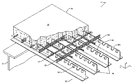
[0027] FIG. 1 is an isometric view of an unfilled grating composite with
reinforced concrete slab;
[00281 FIG. 2 is a cross-section of the deck shown in FIG. 1 having
prestressing
strands;
[0029] FIG. 2A is a cross-section of the deck shown in FIG. 1 having post-
tensioning tendons
[0030] FIG. 3 is a cross-section of the deck shown in FIG. 1, oriented at 90
degrees from the cross-section shown in figure 2;
[0031 ] FIG. 3A is a cross-section of the deck shown in FIG. 1, oriented at 90
degrees from the cross-section shown in figure 2A;
[0032] FIG. 4 shows one embodiment of a main bearing bar where shear transfer
is effected with the use of "C" shaped recesses.
-6-
001.1530687.1
CA 02489170 2004-12-O1
Atty. Dkt. No.: 084158-0135
[0033] FIG. S shows one embodiment of a main bearing bar where shear transfer
is effected with the use of "U" shaped recesses and round holes.
[0034] FIG. 6 shows one embodiment of a main bearing bar where shear transfer
is effected with the use of round holes.
[0035] FIG. 7 shows a temporary support and temporary form pan used in the
forming of the concrete component of the invention;
[0036] FIG. 8 shows the temporary support and temporary form pan illustrated
in
Fig. 7, after the concrete component of the invention has been cast;
[0037] FIG. 9 shows temporary forms still in place after the concrete
component
of the invention has been cast;
DETAILED DESCRIPTION OF THE PREFERRED EMBODIMENTS
[0037] An unfilled grating composite with reinforced concrete slab is
generally
indicated at 10. Unfilled grating composite with reinforced concrete slab 10
is
preferably intended to contact, be supported on, and transmit forces to
support
members 50 either directly or through a concrete haunch to form a structural
floor
which can be a bridge floor, a road bed, a pedestrian walkway, a support floor
for a
building, or the like. Unfilled grid decks composite with reinforced concrete
slabs can
also be used as structural or decorative walls, where support member 50 would
be a
column. Unfilled grating composite with reinforced concrete slab 10 will
typically be
formed off site in modular units and transported to the field and installed,
though it is
also possible to form them in place.
[0038] In its preferred form, unfilled grating composite with reinforced
concrete
slab 10 is a composite structure comprised of an open-lattice grating base
member or
grating component 12, preferably made of steel, and a top component 14,
preferably
made of reinforced concrete. As described in more detail below, a portion of
grating
component 12 is embedded in top component 14 to advantageously transfer
horizontal
shear forces between reinforced concrete component 14 and grating component 12
and to maximize the benefits of the excellent compressive strength of concrete
and the
excellent tensile strength of steel.
001.1530687.1
CA 02489170 2004-12-O1
Atty. Dkt. No.: 084158-0135
[0039] As shown in FIG. 1, grating component 12 includes a plurality of
substantially parallel main bearing bars 16 (shown as extending in the X-
direction).
Grating component 12 does not include tertiary bars or distribution bars.
[0040] As best shown in FIG. 2, main bearing bars 16 are generally and most
efficiently T-shaped and include a lower horizontal section 22, a
substantially planar
intermediate vertical section 24, and a top section 25.
[0041 ] As best shown in FIG 3, assembly apertures or fabrication holes 26 may
be
provided in intermediate vertical sections 24 of main bearing bars 16 to allow
the
insertion of rods or other members to support permanent or temporary formwork
46
for the reinforced concrete component.
[0042] Top component 14 preferably consists of a material capable of being
poured and setting, e.g., concrete 30. In the preferred design, concrete 30 is
reinforced
by a plurality of reinforcing bars, such as shown at 32, and a plurality of
reinforcing
bars, such as shown at 34. Typically, the reinforcing bars 32, 34 are oriented
at right
angles to each other, with one of the bars parallel to main bearing bars 16.
(0043] Prestressing and post-tensioning of concrete is a common technique in
the
manufacture and installation of precast concrete structural elements for
bridges and
buildings. Because concrete is relatively weak in tension, it is prone to
cracking, even -
when reinforcing steel is present to provide adequate strength. Prestressing
or post-
tensioning of concrete puts concrete into compression before the element is
put into
service carrying load. Under load, the precompression of the concrete
counteracts
tensile forces that may be induced, preventing cracking. Prestressing of
concrete is
accomplished by tensioning high strength steel prestressing strand before
concrete is
placed into the formwork. The prestressing strand is located at or close to
the neutral
axis of the concrete in order to prevent distortion of the finished precast
element.
Once the concrete has cured, the ends of the prestressing strand are cut, and
the
resulting contraction of the strand puts the concrete, to which it is now
bonded, into
compression.
[004.4] An alternate way to achieve the.same result of compression within the
concrete top element is to cast hollow tubes, generally known as ducts, into
the
precast concrete element (at or near the neutral axis location). Once the
concrete has
_g_
001.1530687.1
CA 02489170 2004-12-O1
Atty. Dkt. No.: 084158-0135
cured, high strength rods, also known as tendons, are inserted in the ducts,
and
tensioned, such as by using jacks or other commonly used contraction
techniques..
Anchors are attached to the end of the tendons to lock in the tensile force,
and the
jacks are then released. As with prestressing, post-tensioning of a concrete
element
will act to keep it from cracking under load.
[00451 Prestressing strand 37, or post-tensioning ducts 37A and tendons 37B,
are
generally located normal to the main bearing bars 16, but may be skewed in the
construction of skewed unfilled grating composite with reinforced concrete
slab
panels. With sufficient prestressing strand 37, or post-tensioning ducts 37A
and
tendons 37B, reinforcing bars 32 may be eliminated. Prestressing strand 37,or
post-
tensioning ducts 37A and tendons 37B may be placed in the recesses 25A or 25B
or
through the holes 25C in the main bearing bars 16.
[0046] Reinforcing bars and prestressing strand or post-tensioning tendons may
be protected from corrosion by epoxy coating or other means. Main bearing bars
16,
and reinforcing bars 32 and 34 are preferably formed of steel, and epoxy
coated or
galvanized to inhibit corrosion. Alternatives include fiber reinforced
plastics, solid
stainless steel, or carbon steel with stainless steel cladding. Uncoated steel
may be
used in applications where corrosion is not a concern. In lieu of reinforcing
bars 32,
34, a reinforcing mesh may be used to reinforce concrete 30. Where an ultra
high
performance material with adequate tensile strength is substituted for
standard
concrete, reinforcing bars 32, 34 may not be required.
[0047] Reinforced concrete component 14 includes a planar top surface 36
providing a road surface, either directly or with a separate wear surface, and
a planar
bottom surface 38 located below the top surface of main bearing bars 16, and
encompassing the embedded upper portions 25 .of main bearing bars 16.
[0048] Embedded upper portions 25 permit mechanical locks to be formed
between reinforced concrete component 14 and grating component 12 in the
vertical
direction (Z-axis), and in a horizontal plane in the longitudinal (X-axis) and
lateral
(Y-axis) directions. The mechanical locks: (i) assure longitudinal and lateral
horizontal shear transfer from reinforced concrete component 14 to grating
component 12, (ii) prevent separation between reinforced concrete component 14
and
_g_
001.1530687.1
CA 02489170 2004-12-O1
Atty. Dkt. No.: 084158-0135
grating component 12 in the vertical direction, and (iii) provide structural
continuity
with reinforced concrete component 14, permitting reinforced concrete
component 14
and grating component 12 to function in a composite fashion. While a small
chemical
bond may be formed due to the existence of adhesives in the concrete, without
a
mechanical lock in the longitudinal direction (X-axis), the longitudinal shear
transfer
is insufficient to permit reinforced concrete component 14 and grating
component 12
to function in a totally composite fashion.
[0049) In order to provide the mechanical lock between the grating and the top
component, top section 25 of main bearing bar 16 is shaped in the longitudinal
direction (X-axis) to provide gripping surfaces. These may be in any shape to
provide
a connection suitable for the load to be carried. This may be simply deforming
the
top section 25, using cutouts, or some other form of connection.
[00501 In one form of the invention, shown in FIG. 4, the top portion 25 of
the
main bearing bar is shaped with a plurality of "C" shaped recesses 25A. The
recesses
have inwardly inclined side surfaces 28A, and a bottom surface 30A. In another
form
of the invention, shown in FIG. 5, the top portion 25 of the main bearing bar
is shaped
with a plurality of "U" shaped recesses 25B. The recesses have parallel side
surfaces
28B, and a bottom surface 30B. In this form of the invention, a plurality of
holes,
25C may be used to provide mechanical lock in the vertical direction. In a
third form
of the invention, shown in FIG. 5, a plurality of holes 25C, which may be
round or
otherwise, are formed (by drilling, punching, or other means) in the top
portion 25 of
the main bearing bar. The holes 25C have a side surface 28C and a bottom
surface
30C.
[0051 ] In the embodiments described above, in the Y-direction normal to the
main
bearing bar, the upper portion of the main bearing bar 25 without recesses
resists
shear. In the X-direction parallel to the main bearing bar, the concrete
component fills
the "C" shaped recess 25A, the "U" shaped recess 25B, or the holes 25C.
Horizontal
shear resistance is provided by the edge or side wall 28A, 28B, or 28C and by
the
strength of concrete component 30 that fills the recesses and/or holes. In the
Z-
direction, the relatively small vertical separation forces are resisted by the
upper,
-10-
001.1530687.1
CA 02489170 2004-12-O1
Atty. Dkt. No.: 084158-0135
overhanging portion of inclined side surfaces 28A, the bond with the side
surfaces of
28B, or the top portion of the holes 29C.
[0052] In an alternative embodiment, a combination of recesses 25A and/or 25B
and holes 25C may be used.
[0053] To maximize deck strength and minimize deck weight, it is desirable
that
planar bottom surface 38 be located only as required to adequately embed the
shear
connecting mechanisms 25A, 25B, and/or 25C. Concrete 30 does not fill the
interstices 20 of grating component 12. This feature can be achieved by a
number of
different methods.
[0054] In a preferred arrangement, intermediate barriers 46, e.g., strips of
sheet
metal, can be placed onto top surfaces 40 of temporary supports 18 between
adjacent
main bearing bars 16, as shown in FIG. 7 and FIG. 8. When concrete 30 or
another
material is subsequently poured onto grating component 12, intermediate
barriers 46
create a barrier, preventing concrete 30 from traveling therethrough and
filling
interstices 20. Concrete 30 remains on intermediate barriers 46 creating
planar bottom
surface 38 of reinforced concrete component 14. However, in lieu of sheet
metal
strips, expanded metal laths, plastic sheets, fiberglass sheets, or other
material can be
used to create planar bottom surface 38. Additionally, biodegradable sheets,
e.g.,
paper sheets or corrugated cardboard, could also be used, as the primary
purpose of
intermediate barriers 46 is preventing concrete 30 from filling the
interstices 20 of
grating component 12, and this purpose is fully achieved once concrete 30 is
cured.
Once concrete has cured, temporary supports 18 can be removed, and
intermediate
barriers 46 can be removed or left in place.
[0055] Alternatively, planar bottom surface 38 of reinforced concrete
component
14 can be formed by placing a lower barrier, e.g., a form board, underneath
main
bearing bars 16 and filling interstices 20 to the desired level with a
temporary filler
material, e.g., sand, plastic foam or other similar material. Concrete 30 may
then be
poured onto the temporary filler material and the temporary filler material
will
prevent concrete 30 from filling the interstices 20. Once the concrete 30 is
cured, the
lower barrier and temporary filler material can be removed and the deck may be
-1 1-
001.1530687.1
CA 02489170 2004-12-O1
Atty. Dkt. No.: 084158-0135
transported to site for installation. This technique is explained in U.S. Pat.
Nos.
4,780,021 and 4,865,486 which are hereby incorporated by reference herein.
[0056] In the alternative, deck 10 can be formed by placing grating component
12
upside-down on top of reinforced concrete component 14, which would be inside
a
forming fixture, and to gently vibrate both components. Reinforced concrete
component 14 then cures to grating component 12 but does not penetrate and
fill
interstices 20 of grating component 12. One well-known method of vibrating the
components is to use a shake table, but other vibrating devices and techniques
may
also be used.
[0057] Alternatively, as shown in FIG. 9, planar bottom surface 38 of
reinforced
concrete component 14 can be formed by placing temporary form blocks 60, e.g.,
blocks of wood, between the main bearing bars 16 and supported by the tops 22A
of
the bottom flanges 22 of the main bearing bars or by alternative temporary
supports .
When concrete 30 or another material is subsequently poured onto grating
component
12, temporary form blocks 60 create a barrier, preventing concrete 30 from
traveling
therethrough and filling interstices 20. Concrete 30 remains on temporary form
blocks
60 creating planar bottom surface 38 of reinforced concrete component 14.
However,
in lieu of blocks of wood, blocks of foam, plastic, fiberglass, or other
material can be
used to create planar bottom surface 38. Crnce concrete 30 has cured,
temporary form
blocks 60 can be removed.
[0058] Compression-inducing elements, such as prestressing strands 37, or post-
tensioning rods or tendons 37B, consisting of steel, carbon fiber, or other
material, are
placed preferably transverse to main bars 16 within the reinforced concrete
component 14. However, the compression-inducing elements may be placed at an
angle to the main bearing bars to facilitate construction. Even when placed at
an
angle, the compression induced should be in the direction normal to the main
bearing
bars. Compression-inducing elements such as rods 37 induce precompression into
reinforced concrete component 14 before external loads are applied to deck 10.
The
magnitude of precompression in reinforced concrete component 14 provided by
the
compression-inducing elements can be controlled to achieve desirable stress
levels in
reinforced concrete component 14. The preferred embodiment would employ high-
-12-
001.1530687.1
CA 02489170 2004-12-O1
Atty. Dkt. No.: 084158-0135
strength steel strands 37 to prestress reinforced concrete component 14 or
high-
strength steel tendons 37B to post-tension reinforced concrete component 14 to
a level
that would limit transverse concrete stresses below the concrete flexural
cracking
stress when deck 10 is subject to external loads. This would maintain the
stiffness of
deck 10 in the transverse direction, eliminate requirements for distribution
bars and
associated welding, and provide additional confining of concrete 30 within the
shear
connecting mechanisms 25A, 25B, and/or 25C of the main bearing bars 16 to aid
composite action between reinforced concrete component 14 and main bearing
bars
16. Partial-prestressing/post-tensioning may be used to obtain other stress
levels in
reinforced concrete component 14 to achieve desired performance and economy of
deck 10. Coatings and other treatments for the prestressing/post-tensioning
elements
may be employed to enhance their cbrrosion resistance. Other materials may be
used
as prestressing/post-tensioning elements that provide higher strength, higher
ductility,
reduced weight, lower relaxation, reduced anchorage slip, improved corrosion
resistance, lower costs, or other advantages.
[00591 Unfilled grating composite with reinforced concrete slab 10 is
particularly
advantageous because it possesses the same or similar strength and fatigue
life
characteristics as existing unfilled grid decks composite with reinforced
concrete slabs .
having the same section modulus per unit of width. However, deck 10 can be
produced at a substantially lower cost, and with comparable weight. In
unfilled
grating composite with reinforced concrete slab 10, prestressing strand or
post-
tensioning ducts and tendons would be used to provide adequate resistance to
bending
moments in the direction normal to the main bearing bars 16. Sufficient
prestressing
or post-tensioning would be applied to reduce or eliminate cracking of the
concrete in
the direction normal to the main bearing bars 16, thereby extending the life
of the
unfilled grating composite with reinforced concrete slab 10. With sufficient
prestressing or post-tensioning, all of the concrete in the direction normal
to the main
bearing bars could be maintained in compression under service loads, allowing
all of
the concrete to be effective in resisting bending moments in the Y direction.
And, as
unfilled grating composite with reinforced concrete slab deck 10 does not
include
distribution bars, the product cost of the distribution bars and the assembly
costs of
-13-
001.1530687.1
CA 02489170 2004-12-O1
Atty. Dkt. No.: 084158-0135
welding the distribution bars to the main bearing bars at each intersection is
eliminated, and overall product cost is reduced. In addition, grating warpage
due to
hot-dip galvanizing is substantially reduced, further reducing costs, and
providing
additional time savings in erection due to better deck panel tolerances.
(0060] Efficacy and durability of the structural system is greatly increased
by
prestressing or post-tensioning the reinforced concrete component.
Prestressing or
post-tensioning also maximizes the contribution of the concrete component to
the
strength and stiffness of the composite system in the direction normal to the
grating
component, and has the additional benefit of enabling better load distribution
across
multiple elements of the grating component.
(00811 In a preferred embodiment, reinforced concrete component 14 is 5 inch
thick. Main bearing bars 16 are inverted WTSx6 structural T's, with the top
portions
25 thereof being shaped to provide gripping surfaces. Main bearing bars 16
weigh
approximately 6-lbsllinear foot and are spaced apart on 8-inch centers. The
main
bearing bears extend about 1 inch into the concrete component. Reinforcing
bars 34
are preferably #6 rebar spaced apart on 4-inch centers. Reinforcing bars 32
are
preferably #4 rebar spaced apart on 6-inch centers. Prestressing strand 37 is
preferably one half inch diameter, 270,000 pound per square inch high tensile
strength, low relaxation, prestressing strand, stressed to 200,000 pounds per
square
inch when the concrete is placed. In addition, the intermediate barriers 46
are 24-
gauge galvanized sheet metal strips. However, it is recognized that one
skilled in the
art could vary these parameters to meet the design requirements associated
with
specific sites.
[0062] The concrete 30 used may be any standard structural concrete. One
preferred concrete is a high performance concrete because it serves as an
additional
barrier to prevent chlorides and moisture from reaching steel grating
component 12
and causing premature deterioration. A preferred coarse aggregate is 3/4-inch
crushed
stone. A typical high performance concrete substitutes microsilica and fly ash
for a
portion of the Portland cement, and water to cement ratios are limited to 0.40
to
decrease deck permeability and increase strength. A latex modified concrete,
as is
well known in the industry, could also be used as the top layer. Reinforced
concrete
-14-
001.1530687.1
. , , CA 02489170 2004-12-O1
Atty. Dkt. No.: 084158-0135
component 14 may further include an asphaltic concrete or similar material
wear
surface (not shown) applied on top of component 14. Other concrete
formulations
providing adequate compressive strength may also be used. Ultra high
performance
materials may also be used and, with sufficient tensile strength, may reduce
or
eliminate the need for reinforcing steel.
[0063] Main bearing bars 16 are preferably hot rolled steel and may be either
galvanized, coated with an epoxy, or otherwise protected from future
deterioration. In
addition, or as an alternative, stainless steel, or a weathering steel, such
as ASTM
A709 Grade SOW, may be used.
[0064] Specific characteristics of unfilled grid decks composite with
reinforced
concrete slabs and details for manufacturing unfilled grid decks composite
with
reinforced concrete slabs are disclosed in the commonly assigned prior U.S.
Pat. Nos.
4,531,857, 4,531,859, 4,780,021, 4,865,48b, 5,509,243, and 5,664,378 which are
hereby incorporated by reference.
[0065] If desired, shear members, such as vertically oriented studs or dowels,
angles or channels, may be attached to or integrally formed with the upper
portions
25 of main bearing bars 16 to provide additional structure to be embedded into
reinforced concrete component 14. The vertically oriented studs or dowels,
angles or
channels enhance the horizontal shear transfer from reinforced concrete
component 14
to grating component 12.
(00661 Numerous characteristics, advantages, and embodiments of the invention
have been described in detail in the foregoing description with reference to
the
accompanying drawings. However, the disclosure is illustrative only and the
invention
is not limited to the precise illustrated embodiments. Various changes and
modifications may be effected therein by one skilled in the art without
departing from
the scope or spirit of the invention. For example, while the preferred
materials used
for grating component 12 and top component 14 are steel and concrete,
respectively,
fiber-reinforced plastic and an epoxy-aggregate, e.g., epoxy-concrete, could
also
respectively be used. In addition, grating component 12 and top component 14
could
be made from other materials recognized by one of ordinary skill.. . .
-15-
001.1530687.1