Sélection de la langue

Search

Sommaire du brevet 2489548 

Énoncé de désistement de responsabilité concernant l'information provenant de tiers

Une partie des informations de ce site Web a été fournie par des sources externes. Le gouvernement du Canada n'assume aucune responsabilité concernant la précision, l'actualité ou la fiabilité des informations fournies par les sources externes. Les utilisateurs qui désirent employer cette information devraient consulter directement la source des informations. Le contenu fourni par les sources externes n'est pas assujetti aux exigences sur les langues officielles, la protection des renseignements personnels et l'accessibilité.

Disponibilité de l'Abrégé et des Revendications

L'apparition de différences dans le texte et l'image des Revendications et de l'Abrégé dépend du moment auquel le document est publié. Les textes des Revendications et de l'Abrégé sont affichés :

  • lorsque la demande peut être examinée par le public;
  • lorsque le brevet est émis (délivrance).
(12) Brevet: (11) CA 2489548
(54) Titre français: ACCOUPLEMENT POUR BOULONS D'ANCRAGE
(54) Titre anglais: COUPLING OF DRILL ANCHORS
Statut: Périmé et au-delà du délai pour l’annulation
Données bibliographiques
(51) Classification internationale des brevets (CIB):
  • F16L 15/00 (2006.01)
  • E04C 05/16 (2006.01)
  • F16B 07/18 (2006.01)
  • F16L 15/04 (2006.01)
(72) Inventeurs :
  • PAPOUSEK, HERBERT (Autriche)
(73) Titulaires :
  • ATLAS COPCO MAI GMBH
(71) Demandeurs :
  • ATLAS COPCO MAI GMBH (Autriche)
(74) Agent: BORDEN LADNER GERVAIS LLP
(74) Co-agent:
(45) Délivré: 2009-11-10
(86) Date de dépôt PCT: 2003-07-28
(87) Mise à la disponibilité du public: 2004-02-12
Requête d'examen: 2007-02-16
Licence disponible: S.O.
Cédé au domaine public: S.O.
(25) Langue des documents déposés: Anglais

Traité de coopération en matière de brevets (PCT): Oui
(86) Numéro de la demande PCT: PCT/AT2003/000214
(87) Numéro de publication internationale PCT: AT2003000214
(85) Entrée nationale: 2004-12-15

(30) Données de priorité de la demande:
Numéro de la demande Pays / territoire Date
A 1177/2002 (Autriche) 2002-08-01

Abrégés

Abrégé français

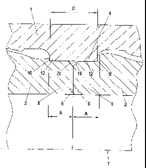
L'invention concerne un accouplement pour boulons d'ancrage, comprenant un manchon (1) à taraudage (5) et deux tubes d'ancrage (2) à filetage (3), dont les extrémités (8) sont vissées dans le manchon (1). Ce manchon (1) porte en son centre longitudinal une nervure annulaire (4) présentant une surface d'extrémité intérieure cylindrique (10). Les extrémités (8) de ces tubes d'ancrage (2) s'engagent dans cette nervure annulaire (4) de façon étanche, lesdites extrémités étant pourvues de surfaces périphériques cylindriques (12) sans filetage. L'objectif de cette invention est d'améliorer l'étanchéité de l'accouplement et de permettre un transfert de l'énergie d'impact à faibles pertes du premier tube d'ancrage (2) au second tube d'ancrage (2). A cet effet, les faces de contact annulaires (6) de ces tubes d'ancrage (2) reposent l'une contre l'autre de façon étanche dans la zone de ladite nervure annulaire (4). On obtient ainsi un accouplement pour boulon d'ancrage sans fuite et empêchant l'échappement du milieu d'injection et/ou de la masse à prise.


Abrégé anglais


The invention relates to a coupling for anchor bolts, comprising a sleeve (1)
having an internal screw thread (5) and two anchor pipes (2) having an
external screw thread (3), the ends (8) of said pipes being screwed into the
sleeve (1). Said sleeve (1) is provided with an annular rib (4) in the
longitudinal centre thereof, said rib having a cylindrical inner end surface
(10). The ends (8) of the anchor pipes (2) engage in the annular rib (4) in a
sealing manner, said ends being embodied with cylindrical thread-free
circumferential surfaces (12) for this purpose. In order to improve the
tightness of the coupling and to ensure that the transfer of impact energy
from the first anchor pipe (2) to the second anchor pipe (2) does not engender
much loss, the annular front surfaces (6) of the anchor pipes (2) are arranged
against each other in a sealing manner in the region of the annular rib (4).
In this way, a leak-free coupling for anchor bolts is provided, said coupling
preventing the discharge of rinsing medium and/or setting mass.

Revendications

Note : Les revendications sont présentées dans la langue officielle dans laquelle elles ont été soumises.


CLAIMS:
1. A coupling of drill anchors, comprising:
a sleeve (1) with an inside thread (5) and with two anchor pipes (2) which
bear an
outside thread (3) and which are screwed into the sleeve (1) from opposing
sides;
an annular rib (4) substantially in the lengthwise middle of the sleeve (1)
and which
projects to an inside;
front surfaces (6) of ends (8) of the anchor pipes (2), which ends are held in
the
sleeve (1), being located in the area of the annular rib (4) and directly
adjoining one
another; and
wherein the annular rib (4) has a cylindrical inner end surface (10), that
outside
surfaces (12) of the cylindrically shaped, thread-free ends (8) of the anchor
pipes (2) adjoin
the cylindrical inner end surface (10) of the annular rib (4), forming a seal,
that the front
surfaces (6) of the anchor pipes (2) each have a chamfer at least on one of an
inside (22)
and an outside (20), that there is at least one annular seal (21) on the
annular rib (4), and
that the anchor pipes (2) with the chamfers (20) on the outside edge of their
front surfaces
(6) adjoin the annular seal (21) which is disposed in the space bounded by
said chamfers
(20) and said rib (4), and side surfaces (16) of the annular rib (4) are
aligned normally to an
axis (7) of the sleeve (1), the front surfaces (6) of the anchor pipes (2)
adjoining one
another to form a seal.
2. The coupling as claimed in claim 1, wherein in the sleeve (1) on either
side of the
annular rib (4) there are areas (14) which have no inside thread.
3. The coupling as claimed in claim 1, wherein the width (B) of the annular
rib (4)
measured in the direction of the axis (7) of the sleeve (1) is substantially
the same size as
the sum of the lengths (A) of the cylindrically shaped, thread-free ends (8)
of the anchor
pipes (2), that is, lengths measured in the lengthwise direction of the anchor
pipes (2).
-10-

4. The coupling as claimed in claim 1, wherein the annular seal (21) is
inserted into an
annular groove which is open to the inside in the cylindrical inner end
surface (10) of the
annular rib (4).
5. The coupling as claimed in claim 4, wherein the part of the annular seal
(21) which
projects over the cylindrical inner end surface (10) of the annular rib (4) is
deformed by the
chamfers (20) of the front surfaces (6) of the anchor pipes (2).
6. The coupling as claimed in claim 1, wherein the annular seal (21) is
disposed in the
space bounded by said chamfers (20) and said cylindrical inner end surface
(10).
7. A coupling of drill anchors, comprising:
a sleeve (1) with an inside thread (5) and with two anchor pipes (2) which
bear an
outside thread (3) and which are screwed into the sleeve (1) from opposing
sides;
an annular rib (4) substantially in the lengthwise middle of the sleeve (1)
and which
projects to an inside;
front surfaces (6) of ends (8) of the anchor pipes (2), which ends are held in
the
sleeve (1), being located in the area of the annular rib (4) and directly
adjoining one
another; and
wherein the annular rib (4) has a cylindrical inner end surface (10), that
outside
surfaces (12) of the cylindrically shaped, thread-free ends (8) of the anchor
pipes (2) adjoin
the cylindrical inner end surface (10) of the annular rib (4), forming a seal,
that the front
surfaces (6) of the anchor pipes (2) each have a chamfer at least on one of an
inside (22)
and an outside (20), that there is at least one annular seal (21) on the
annular rib (4), and
that the anchor pipes (2) with the chamfers (20) on the outside edge of their
front surfaces
(6) adjoin the annular seal (21) which is disposed in the space bounded by
said chamfers
(20) and said rib (4), and side surfaces (16) of the annular rib (4) are
aligned normally to an
axis (7) of the sleeve (1), the side surfaces (16) of the annular rib (1) with
radii passing into
the inside surface of the sleeve (1), into segments (14) which are free of
threads.
-11-

8. The coupling as claimed in claim 7, wherein the front surfaces (6) of the
anchor
pipes (2) adjoin one another to form a seal.
9. The coupling as claimed in claim 7, wherein in the sleeve (1) on either
side of the
annular rib (4) there are areas (14) which have no inside thread.
10. The coupling as claimed in claim 7, wherein the width (B) of the annular
rib (4)
measured in the direction of the axis (7) of the sleeve (1) is substantially
the same size as
the sum of the lengths (A) of the cylindrically shaped, thread-free ends (8)
of the anchor
pipes (2), that is, lengths measured in the lengthwise direction of the anchor
pipes (2).
11. The coupling as claimed in claim 7, wherein the annular seal (21) is
inserted into an
annular groove which is open to the inside in the cylindrical inner end
surface (10) of the
annular rib (4).
12. The coupling as claimed in claim 11, wherein the part of the annular seal
(21)
which projects over the cylindrical inner end surface (10) of the annular rib
(4) is deformed
by the chamfers (20) of the front surfaces (6) of the anchor pipes (2).
13. The coupling as claimed in claim 7, wherein the annular seal (21) is
disposed in the
space bounded by said chamfers (20) and said cylindrical inner end surface
(10).
14. A coupling of drill anchors, comprising:
a sleeve (1) with an inside thread (5) and with two anchor pipes (2) which
bear an
outside thread (3) and which are screwed into the sleeve (1) from opposing
sides;
an annular rib (4) substantially in the lengthwise middle of the sleeve (1)
and which
projects to an inside;
-12-

front surfaces (6) of ends (8) of the anchor pipes (2), which ends are held in
the
sleeve (1), being located in the area of the annular rib (4) and directly
adjoining one
another; and
wherein the annular rib (4) has a cylindrical inner end surface (10), that
outside
surfaces (12) of the cylindrically shaped, thread-free ends (8) of the anchor
pipes (2) adjoin
the cylindrical inner end surface (10) of the annular rib (4), forming a seal,
that the front
surfaces (6) of the anchor pipes (2) each have a chamfer at least on one of an
inside (22)
and an outside (20), that there is at least one annular seal (21) on the
annular rib (4), and
that the anchor pipes (2) with the chamfers (20) on the outside edge of their
front surfaces
(6) adjoin the annular seal (21) which is disposed in the space bounded by
said chamfers
(20) and said rib (4), and side surfaces (16) of the annular rib (4) are
aligned normally to an
axis (7) of the sleeve (1), the front surfaces (6) of the anchor pipes (1)
having a chamfer
(22) inside.
15. The coupling as claimed in claim 14, wherein the front surfaces (6) of the
anchor
pipes (2) adjoin one another to form a seal.
16. The coupling as claimed in claim 14, wherein in the sleeve (1) on either
side of the
annular rib (4) there are areas (14) which have no inside thread.
17. The coupling as claimed in claim 14, wherein the width (B) of the annular
rib (4)
measured in the direction of the axis (7) of the sleeve (1) is substantially
the same size as
the sum of the lengths (A) of the cylindrically shaped, thread-free ends (8)
of the anchor
pipes (2), that is, lengths measured in the lengthwise direction of the anchor
pipes (2).
18. The coupling as claimed in claim 14, wherein the annular seal (21) is
inserted into
an annular groove which is open to the inside in the cylindrical inner end
surface (10) of
the annular rib (4).
-13-

19. The coupling as claimed in claim 18, wherein the part of the annular seal
(21)
which projects over the cylindrical inner end surface (10) of the annular rib
(4) is deformed
by the chamfers (20) of the front surfaces (6) of the anchor pipes (2).
20. The coupling as claimed in claim 14, wherein the annular seal (21) is
disposed in
the space bounded by said chamfers (20) and said cylindrical inner end surface
(10).
-14-

Description

Note : Les descriptions sont présentées dans la langue officielle dans laquelle elles ont été soumises.


CA 02489548 2004-12-15
Coupling of drill anchors
The invention relates to a coupling of drill anchors with a sleeve with an
inside thread and
with two anchor pipes which bear an outside thread and which are screwed into
the sleeve from
opposing sides, with the features of the introductory part of the independent
claim 1.
The problem in couplings for anchor pipes is that the flushing medium (air or
water)
which flows through the cavity of the anchor pipes while drilling and the
setting mass (for
example cement mortar) which is pressed through the cavity of the anchor pipes
toward their
front end which is held in the borehole after completion of the borehole can
escape in the. area of
known couplings. In this way losses of flushing media occur and in the case of
setting mass with
leaky couplings plugs of setting mass form which prevent complete filling of
the borehole around
the drill anchor.
A coupling of the initially mentioned type is known from DE-A-42 20 636. DE-A-
4 220
636 shows a coupling of drill anchors with a sleeve with an inside thread and
with two anchor
pipes which bear an outside thread and which are screwed into the sleeve from
opposing sides,
essentially in the lengthwise middle of the sleeve there being an annular rib
which projects to the
inside, and the front surfaces of the ends of the anchor pipes held in the
sleeves being located in
the area of the annular rib and directly adjoining one another, the outside
surfaces of the ends of
the anchor pipes adjoining the inner end surface of the annular rib, forming a
seal. In the
coupling as claimed in DE-A-42 20 636 there are annular seals located next to
the annular rib.

CA 02489548 2004-12-15
The object of the invention is to make available a coupling of the initially
mentioned type
which even under the loads which occur during drilling (rotary-impact movement
of the drill
anchor) is and remains reliably tight.
This object is achieved as claimed in the invention with a coupling which has
the features
of claim 1.
Amended page
2

CA 02489548 2004-12-15
Preferred and advantageous embodiments of the coupling as claimed in the
invention are
the subject matter of the dependent claims.
Since in the coupling as claimed in the invention the ends of the anchor pipes
which have
been screwed into the sleeve fit into the annular rib which is provided in the
sleeve, forming a
seal, and due to the annular seal which is provided as claimed in the
invention on the annular rib,
the escape of flushing medium and/or setting mass in the. area of the coupling
is prevented.
If according to one preferred embodiment of the coupling as claimed in the
invention it is
provided that the ends of the anchor pipes, which ends are held in the sleeve,
and which anchor
pipes directly adjoin one another with their front surfaces, directly adjoin
one another with their
front surfaces to form a seal, additional sealing in the area of the coupling
is ensured, since
between the ends of the anchor pipes located in the coupling the flushing
medium and/or the
setting mass cannot escape. In addition, this measure of the invention has the
advantage that the
rotary-impact force which warps the drill anchor when drilling a hole in rock
is less of a problem,
since transmission takes place directly from anchor pipe to anchor pipe.
Other details, features and advantages of the coupling as claimed in the
invention result
from the following description of the embodiment which is shown by way of
example in the
drawings.
Figure 1 shows a coupling partially in a section,
Figure 2 shows the adjoining ends of anchor pipes (without the sleeve)
enlarged and
partially cutaway,
Figure 3 shows a sleeve in a lengthwise section,
Figure 4 shows detail IV from Figure 3,

CA 02489548 2004-12-15
Figure 5 shows an anchor pipe, partially in a section,
Figure 6 shows detail VI from Figure 5,
Amended page

CA 02489548 2004-12-15
Figure 7 shows enlarged a detail of the coupling in the area of the annular
rib of the
sleeve and
Figure 8 shows a coupling as claimed in the invention with the sleeve.
As shown in Figure L, a coupling consists of a sleeve I and two anchor pipes 2
which are
held with their ends 8 in the sleeve 1.
The sleeve 2 has two internally threaded segments 5 which are separated from
one
another by an annular rib 4 which projects to the inside; the threads of the
segments run in the
same direction. On their outer surface the anchor pipes 2 bear an outside
thread 3 which matches
the inside thread 5 of the sleeve 1.
The anchor pipes 2, preferably on the two ends 8, have a segment without an
inside thread
which extends away from the front surfaces 6 of the anchor pipe 2. This
segment without a thread
is made with a cylindrical outside surface 12. The front surfaces 6 of the
anchor pipes 2 which
are made annular have a chamfer 20 outside and optionally a chamfer 22 inside
(Figure 6).
The annular rib 4 which is located in the lengthwise middle of the sleeve 1
has a
cylindrical inner end surface 10 and two side surfaces 16 which are
essentially normal to the axis
7 of the sleeve 1 and which on either side of the annular rib 4 with a radius
(curvature) pass into
the segment 14 of the inside surface of the sleeve 2, that is, the segment
without an inside thread.
The situation for an assembled coupling is shown in Figure 7. It is apparent
that the
anchor pipes 2 with their thread-free ends 8 are located within an annular rib
4, the cylinder
surfaces 12 on the ends 8 of the anchor pipes 2 adjoining the inner end
surface 10 of the annular
rib 4, fonming a seal (the gap shown in Figure 7 between the surfaces 10 and
12 in practice is not
present and is shown only for the sake of clarity).
S

CA 02489548 2004-12-15
Figure 7 also shows that the annular front surfaces 6 of the ends 8 of the
anchor pipes 2
directly adjoin one another to form a seal.
The width B of the annular rib 4, therefore the length of the cylindrical
inner end surface
1 U of the annular rib 4, which length is measured in the direction of the
axis 7 of the sleeve
Amended page
6

CA 02489548 2004-12-15
1, is roughly as great as the sum of the length A of the thread-free segments
12 on the ends 8 of
the anchor pipes 2, which length is measured in the direction of the axis,
i.e. in the lengthwise
direction of the anchor pipes 2. This results in that a sleeve 1 cannot be
screwed too far onto the
anchor pipe 2 since the shoulder on the end of the cylinder surface 12 of the
anchor pipe 2 strikes
the side surface 16 of the annular rib 4 when the front surface 6 of this
anchor pipe 2 is located
roughly in the middle of the lengthwise extension of the rib 4. Thus it is
ensured that there is an
essentially symmetrical structure of the coupling as claimed in the invention
consisting of the
sleeve 1 and two anchor pipes 2 which are held (screwed) in it.
In the coupling in accordance with the invention which is shown in Figure 8,
in the
cylinder surface of the annular rib 4 which points to the inside there is an
annular groove in
which an annular seal 21 of elastic material (O-ring) is inserted.
The anchor pipes 2 which are screwed into the sleeve 1 with their chamfers 20
on the
outside edge of the front surfaces 6 which also adjoin one another in this
embodiment adjoin the
annular seal 21 so that the seal between the two anchor pipes 2 is further
improved in the area of
the coupling.
It should be pointed out that in Figure 8 the annular seal 21 is shown
"idealized",
therefore with its original round cross sectional shape. In fact, in the
assembled state of the
coupling it will be deformed in its part which projects over the inside
surface of the a.rmular rib 4
into a triangular cross sectional shape according to the outside chamfers 20
on the end surfaces 6
of the anchor pipes 2.
The cross sectional shape of the annular seal 21 need not be round. For
example the
annular seal can have a polygonal cross sectional shape (rectangular or
quadratic). It i s also
7

CA 02489548 2004-12-15
conceivable for the part of the annular seal 21 which projects over the inside
surface of the
annular rib 4 to have a wedge-shaped cross sectional shape which tapers
radially to the inside.
In sunumary, one preferred embodiment of the invention can be described as
follows:
Amended page
8

CA 02489548 2004-12-15
A coupling of drill anchors has a sleeve 1 with an inside thread 5 and two
anchor pipes 2
which are provided with an outside thread 3 and which have ends 8 which are
screwed into the
sleeve 1. The sleeve 1 in its lengthwise middle bears an annular rib 4 with a
cylindrical inner end
surface 10. The ends 8 of the anchor pipes 2 fit into this annular rib 4 to
form a seal, for which
they are made with cylindrical, thread-free peripheral surfaces 12. In order
to improve the
tightness of the coupling and to make the transmission of impact energy from
the anchor pipe 2
to the anchor pipe 2 experience less loss, the annular front surfaces 6 of the
anchor pipes 2 adjoin
one another in the area of the annular rib 4 to form a seal. Thus a coupling
for drill anchors is
made available which is free of leaks and which prevents the escape of the
flushing medium
and/or setting mass.
Amended page
9

Dessin représentatif
Une figure unique qui représente un dessin illustrant l'invention.
États administratifs

2024-08-01 : Dans le cadre de la transition vers les Brevets de nouvelle génération (BNG), la base de données sur les brevets canadiens (BDBC) contient désormais un Historique d'événement plus détaillé, qui reproduit le Journal des événements de notre nouvelle solution interne.

Veuillez noter que les événements débutant par « Inactive : » se réfèrent à des événements qui ne sont plus utilisés dans notre nouvelle solution interne.

Pour une meilleure compréhension de l'état de la demande ou brevet qui figure sur cette page, la rubrique Mise en garde , et les descriptions de Brevet , Historique d'événement , Taxes périodiques et Historique des paiements devraient être consultées.

Historique d'événement

Description Date
Le délai pour l'annulation est expiré 2015-07-28
Lettre envoyée 2014-07-28
Accordé par délivrance 2009-11-10
Inactive : Page couverture publiée 2009-11-09
Inactive : Taxe finale reçue 2009-08-21
Préoctroi 2009-08-21
Lettre envoyée 2009-03-17
Un avis d'acceptation est envoyé 2009-03-17
Inactive : Approuvée aux fins d'acceptation (AFA) 2009-03-02
Modification reçue - modification volontaire 2009-01-14
Inactive : Dem. de l'examinateur par.30(2) Règles 2008-11-27
Modification reçue - modification volontaire 2007-03-20
Lettre envoyée 2007-03-07
Exigences pour une requête d'examen - jugée conforme 2007-02-16
Requête d'examen reçue 2007-02-16
Toutes les exigences pour l'examen - jugée conforme 2007-02-16
Inactive : CIB de MCD 2006-03-12
Lettre envoyée 2005-04-26
Inactive : IPRP reçu 2005-04-01
Inactive : Transfert individuel 2005-03-21
Inactive : Lettre de courtoisie - Preuve 2005-03-01
Inactive : Page couverture publiée 2005-03-01
Inactive : Notice - Entrée phase nat. - Pas de RE 2005-02-25
Requête pour le changement d'adresse ou de mode de correspondance reçue 2005-02-07
Demande reçue - PCT 2005-01-21
Exigences pour l'entrée dans la phase nationale - jugée conforme 2004-12-15
Demande publiée (accessible au public) 2004-02-12

Historique d'abandonnement

Il n'y a pas d'historique d'abandonnement

Taxes périodiques

Le dernier paiement a été reçu le 2009-07-20

Avis : Si le paiement en totalité n'a pas été reçu au plus tard à la date indiquée, une taxe supplémentaire peut être imposée, soit une des taxes suivantes :

  • taxe de rétablissement ;
  • taxe pour paiement en souffrance ; ou
  • taxe additionnelle pour le renversement d'une péremption réputée.

Les taxes sur les brevets sont ajustées au 1er janvier de chaque année. Les montants ci-dessus sont les montants actuels s'ils sont reçus au plus tard le 31 décembre de l'année en cours.
Veuillez vous référer à la page web des taxes sur les brevets de l'OPIC pour voir tous les montants actuels des taxes.

Historique des taxes

Type de taxes Anniversaire Échéance Date payée
Taxe nationale de base - générale 2004-12-15
Enregistrement d'un document 2005-03-21
TM (demande, 2e anniv.) - générale 02 2005-07-28 2005-07-07
TM (demande, 3e anniv.) - générale 03 2006-07-28 2006-05-25
Requête d'examen - générale 2007-02-16
TM (demande, 4e anniv.) - générale 04 2007-07-30 2007-07-18
TM (demande, 5e anniv.) - générale 05 2008-07-28 2008-07-25
TM (demande, 6e anniv.) - générale 06 2009-07-28 2009-07-20
Taxe finale - générale 2009-08-21
TM (brevet, 7e anniv.) - générale 2010-07-28 2010-07-16
TM (brevet, 8e anniv.) - générale 2011-07-28 2011-07-27
TM (brevet, 9e anniv.) - générale 2012-07-30 2012-07-13
TM (brevet, 10e anniv.) - générale 2013-07-29 2013-06-18
Titulaires au dossier

Les titulaires actuels et antérieures au dossier sont affichés en ordre alphabétique.

Titulaires actuels au dossier
ATLAS COPCO MAI GMBH
Titulaires antérieures au dossier
HERBERT PAPOUSEK
Les propriétaires antérieurs qui ne figurent pas dans la liste des « Propriétaires au dossier » apparaîtront dans d'autres documents au dossier.
Documents

Pour visionner les fichiers sélectionnés, entrer le code reCAPTCHA :


Pour visualiser une image, cliquer sur un lien dans la colonne description du document (Temporairement non-disponible). Pour télécharger l'image (les images), cliquer l'une ou plusieurs cases à cocher dans la première colonne et ensuite cliquer sur le bouton "Télécharger sélection en format PDF (archive Zip)" ou le bouton "Télécharger sélection (en un fichier PDF fusionné)".

Liste des documents de brevet publiés et non publiés sur la BDBC .

Si vous avez des difficultés à accéder au contenu, veuillez communiquer avec le Centre de services à la clientèle au 1-866-997-1936, ou envoyer un courriel au Centre de service à la clientèle de l'OPIC.

({010=Tous les documents, 020=Au moment du dépôt, 030=Au moment de la mise à la disponibilité du public, 040=À la délivrance, 050=Examen, 060=Correspondance reçue, 070=Divers, 080=Correspondance envoyée, 090=Paiement})


Description du
Document 
Date
(aaaa-mm-jj) 
Nombre de pages   Taille de l'image (Ko) 
Dessins 2004-12-14 4 81
Dessin représentatif 2004-12-14 1 18
Description 2004-12-14 9 209
Revendications 2004-12-14 3 65
Abrégé 2004-12-14 1 26
Revendications 2009-01-13 5 171
Dessin représentatif 2009-10-16 1 12
Rappel de taxe de maintien due 2005-03-29 1 111
Avis d'entree dans la phase nationale 2005-02-24 1 193
Courtoisie - Certificat d'enregistrement (document(s) connexe(s)) 2005-04-25 1 104
Accusé de réception de la requête d'examen 2007-03-06 1 176
Avis du commissaire - Demande jugée acceptable 2009-03-16 1 162
Avis concernant la taxe de maintien 2014-09-07 1 170
PCT 2004-12-14 12 439
Correspondance 2005-02-06 1 24
Correspondance 2005-02-24 1 26
PCT 2004-12-15 4 175
Correspondance 2009-08-20 1 32