Note : Les descriptions sont présentées dans la langue officielle dans laquelle elles ont été soumises.
CA 02489599 2004-12-07
CUSTOMIZABLE DRAIN GUARD
1. TECHNICAL FIELD
S The present invention relates to drain guards for use in gutters to prevent
clogging of the
gutters and downspouts. In particular, a gutter drain spout guard with a box-
shaped central portion
and two rotatable and detachable sloping wings is disclosed. The drain guard
is modular,
customizable and easy to manufacture and install and minimizes gutter
maintenance.
2. BACKGROUND OF THE INVENTION
Drains and gutters are used to channel the flow of excess water from buildings
thereby
avoiding water damage. The roofs of houses and buildings commonly incorporate
rain gutters or
eaves troughs that collect and redirect rainwater.
Water flow through the downspouts often contains large particles or debris
such as foliage
and sediment which will block or restrict drainage if it is not removed.
Damage may then occur
not only to the gutter system, but to the building structure itself.
Many devices have been developed to reduce clogging of gutter systems by
attempting to
filter out debris, preventing it from entering and blocking the downspout yet,
allowing water to
pass uninterrupted through the filter.
For example, U.S. Pat. No. 5,242,591 ("'591") issued to Beechert consists of
wire-mesh
sheets folded into elongated boxes which are placed in open drains, shielding
the drain from leaves
and other debris. The box design of the '591 Patent is awkward to install as
the entire drain must
be filled with the mesh boxing. T'he cost of installation is, therefore, high
and the boxing must be
customized to fit around obstacles such as supports and corners.
U.S. Pat. No. 2,8?5,?12 ("'712") issued to Blau shows a downspout shield that
is hinged
and held in place at the corner of the eaves trough. It has an additional anti-
clogging device placed
under the shield above the downspout. The '? 12 Patent is complex in
construction, including the
hinge system, attachment means and separate anti-clogging device required,
further rendering the
device difficult to install. The '?12 Patent does not appear to protect a
downspout that is situated
in the middle of a length of gutter. Additionally, both the '591 and '712
Patents are suitable for
"U" shaped gutters only, which are currently extremely rare in North America.
U.S. Pat. No. 5,409,602 ("'602") to Sorenson discloses an inverted U-shaped
drain guard
CA 02489599 2004-12-07
with slots for use in a conventional flat bottomed gutter system. The '602
device is difficult to
manufacture, fits only a single drain size, is not customizable and
inefficient at straining, and not
suitable for downspouts at an end of a gutter, as if designed for downspouts
with gutter floor space
on each side of the drain hole.
The present invention satisfies the need for an easy and economical device to
manufacture
and install which optimizes water flow therethrough while blocking debris, and
is customizable to
fit varying gutter designs.
3. SUMMARY OF THE INVENTION
A perforated drain guard adapted to stop debris from passing therethrough,
while
permitting the passage of fluid, comprised of an inverted U-shape central
portion having a top and
two sides and at least one inverted U-shaped, sloped central wing projecting
from the central
portion, with a plurality of openings, is disclosed.
The wings are removeably attached to the central portion at a single edge,
permitting easy
customization by snapping off the modular wing where it is not required, for
instance in a channel
with a vertical wall adjacent to a drain hole. The drain guard may also have a
tang at the foot of
each wing to provide a stable base and attachment point between the drain
guard and the floor of
the channel or gutter.
A method of installation is disclosed whereby the wings of the drain guard are
rotated
downwards if the gutter floor around the drain hole is raised, then caulking
or other adhesives is
applied to the bottom edges of the drain guard and the underside of the tangs.
The drain guard is
then fixed in place with the central portion directly over the drain hole.
A method of manufacturing a drain guard is also disclosed wherein a flat drain
guard blank
is punched out, preferably of 24 gauge stainless steel, including the distinct
central and wing
segments and a plurality of openings therethrough. The two sides of the
central portion are bent
downwards at substantially 90° in relation to the flat central portion,
and the two flaps of the wing
portions are bent downwards at substantially 90° to the flat wing
portion.
2
CA 02489599 2004-12-07
4. BRIEF DESCRIPTION OF THE DRAWINGS
The apparatus and method of the present invention will now be described with
reference to
the accompanying drawing figures, in which:
FIG. 1 is a perspective view of the drain guard installed in a conventional
gutter over a
drain hole, according to the invention.
FIG. 2 is an elevation view of a drain guard, according to the invention.
FIG. 3 is a plan view of a drain guard in a conventional gutter, according to
the invention.
FIG. 4 is a plan view of a stamped out drain guard sheet during manufacture,
according to
the invention.
5. DETAILED DESCRIPTION OF THE INVENTION
Maintaining gutters and down pipes free from debris is a constant building
maintenance
challenge. The present invention provides an economical, easy to manufacture
solution in the
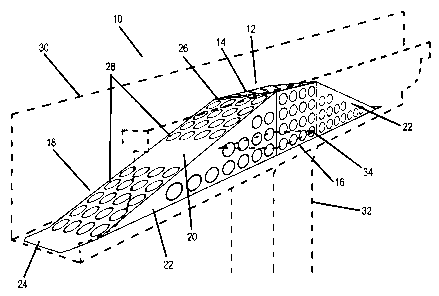
form of a modular, customizable and easy to install drain guard 10. Refernng
to Figure 1, a
perspective view of the drain guard 10 installed in a conventional gutter 30
(dotted outline) over a
drain hole 34 is shown. The drain guard 10 in assembled form is an elongated
hollow structure
comprised of three segmented components. The underside of the drain guard 10
is open. While
the preferred embodiment is described in terms of a drain guard 10 in a gutter
30, it should be
appreciated that the drain guard may be used in any channel for liquid having
a drain.
The central portion or box 12 of the drain guard 10 is generally cube shaped,
formed by an
inverted U-shape with an open base. The top 14 of the box 12 is substantially
a square panel with
four edges, a front and back edge and two side edges. In the preferred
embodiment, a square side
panel 16 projects downwards from each of the two side edges of the top 14 of
the box 12. A
hollow wing 18 is rotatably attached to both the front and back edges of the
top panel 14. The wing
18, attached to the front edge of the top panel 14, is attached via a row of
perforations 26 so that it
can be easily detached during customization to a particular channel structure.
In a variation, both
edges of the top 14 of the box 12 to which a wing 18 is attached are
perforated. Each wing
comprises an angled top 20 which slopes down and away from the top panel 14 of
the box 12 to the
base at an angle below horizontal. A substantially triangular flap 22 projects
downwards and
preferably substantially vertically and at 90° from the left and right
sides of the top panel 20 of the
CA 02489599 2004-12-07
wing 18. A tang 24 projects from the front or distal edge of each wing 18 such
that, in the preferred
embodiment, the tang 24 lies horizontal and parallel to the top 14 of the box
12. The bottom edges
of the side panels 16 of the box 12, the flaps 22 and the tang 24 all lie,
before customization, on the
same horizontal plane. The back edge of the top 20 of the wing 18 is attached
to the top panel 14 of
the box 12. The top panel 14 of the box 12, top panels 20 of the wing 18, side
panels 16 and flaps
22 are all perforated with a plurality of holes 28. Preferably the
perforations or holes 28 are
circular and between 5 mm and 15 mm in diameter. The optimal hole 28 size has
been found to be
9.53 mm (3/8"). The optimal hole 28 size is the size most effective for
blocking or filtering debris
while permitting maximal water flow through the drain guard 10. In variations,
other hole 28
diameters may be employed.
The tangs 24 at the end of each wing 18 are tapered, such that the edge of the
tang 24
abutting the edge of the wing 18 is wider than the distal edge of the tang 24.
This assists in
directing sludge in the gutter 30 moving to the sides of the drain guard 10
rather than up and
through the holes 28.
Conventional gutters 30 are typically flat bottomed and of standard
dimensions. The
optimal drain guard 10 dimensions for use in conventional gutters 30 are 343
mm (13.5") long by
57.2 mm (2.25") wide by 57.2 mm (2.25") high. The dimensions, as can be
appreciated by one
skilled in the art, are dependent on the gutter 30 size, and accordingly the
invention 10 can be
scaled up or down to suit different channel designs. In variations where the
drain is of a large size,
for instance in industrial applications, the drain guard 10 is of a size
sufficient to cover the drain
hole 34. The present invention can be installed in a wide range of gutter 30
sizes as it is of lesser
dimensions that then gutter 30 and is placed over the drain hole 34 regardless
of the location of the
side walls of the gutter 30.
The drain guard 10 design allows for debris to be swept from the roof into the
gutter rather
than piling on the roof or falling below, often onto paths, as with
conventional drain guards. The
debris can then be removed from the gutters during maintenance. The drain
guard 10 is narrower
than the gutter 30, thereby permitting debris and sludge to pass along the
sides of the guard 10
while not blocking water flow. Debris may move up the sloped wings 18 and fall
to the sides of the
guard 10, unlike known drain guards which are of the same width as the gutter
30.
The drain guard is optimally comprised of 24 gauge stainless steel, such that
it is
lightweight, and cheap and easy to manufacture and install. Other materials
such as plastic or
other substitutes may be used in variations, however.
In variations, the central portion 12 and wings 18 may be of other shapes and
contours,
such as curved, parabolic, and cylindrical. The sloping ramp structure of the
wing 18 of the
4
CA 02489599 2004-12-07
preferred embodiment is optimal.
Figure 2 is an elevation view of the drain guard 10 with dotted lines around
the wing 18 and
box 12 sections of the drain guard 10.
Installation is straightforward and can be performed by home owners or
maintenance
workers. Referring now to Figure 3, a plan view of the drain guard 10
installed in a conventional
gutter 30 is shown. During installation, the down pipe 32 placement in
relation to the gutter 30
must be evaluated by the installer. The drain guard 10 can be customized to
fit many variations of
gutter 30 and down pipe 32 design. Some examples of customization follow but
are not intended
to be limiting. If the gutter 30 is continuous on each side of the drain hole
34 at the mouth of the
down pipe 32, the full drain guard 10 unit is placed open side down in the
gutter 30, with an
adhesive on the underside of each tang 24, and the bottom edges of the drain
guard 10, thereby
retaining the drain guard 10 in place over the drain hole 34. The adhesive is
optimally caulking,
but other adhesives may be used, or any bonding agent suitable for the
material of a particular
drain guard 10 and gutter 30.
If one side of the gutter 30 adjacent to the drain hole 34 is discontinuous,
typically at the
end of the gutter 30 where it is capped by a vertical wall at the corner of a
building, the installer
simply bends one wing 18 of the drain guard 10 back and forth. The wing 18
naturally hinges at
the perforated edge 26 of the top panel 20, and the perforated joint quickly
breaks due to metal
fatigue, without the use of tools. The drain guard 10 is then installed with
adhesive on the open
edges of the box 10 abutting the end gutter wall (not shown), and underneath
the remaining tang 24
on the wing 18 projecting away from the gutter 30 wall. The box 12 is thereby
securely located
over the drain hole 34. The second wing 18 is not required, as in this case,
water and debris will
only approach the drain hole 34 from the continuous side of the gutter 30.
If the bottom of the gutter 30 is angled adjacent to the drain hole 34, the
drain guard 10 is
bent slightly so that its underside is contiguous with the gutter 30.
It is often the case that the gutter 30 bottom is raised immediately adjacent
to the drain hole
34, either with caulking or a plastic insert. Conventional drain guards do not
address this issue,
leaving a gap through which debris can enter the downpipe 32. The present
invention, however, is
easily installed by bending the flaps 22 of each wing 18 slightly towards the
middle or center line
of the drain guard 10 so that they can pass by the sides 16 of the box 12.
Both wings 18 are then
rotated about the joint with the top 14 of the box 12 and inward, so that the
flaps 22 slightly overlap
the sides 16 of the box 12. The box 12 is thereby slightly raised in relation
to the wings 18, and
seats against the raised portion of the gutter 30 floor with the bottom of the
wings 18 substantially
flush with the gutter 30 floor as well. In this manner, the drain guard is
customized for the
5
CA 02489599 2004-12-07
particular gutter 30 design and effectively blocks debris.
The drain guard 10 easily slides under the transverse gutter 30 supports or
brackets (not
shown) commonly used to retain the gutter 30 against the building. It is
significant that the box 12
is always located immediately above the drain hole 34. As the top 14 of the
box 12 is the highest
point of the drain guard 10, it performs most effectively by tenting debris
with an apex over the
drain hole 34, thereby maximizing water flaw from the gutter 30 into the drain
hole 34.
Furthermore, the flexible nature of the drain guard 10 permits the installer
to bend the drain
guard 10 to conform to particular characteristics of the gutter 30 or channel.
The sides 16 and flaps
22 may be bent to any angle in relation to the top of the drain guard 10, from
0° to 135°, and from
straight to convex or concave.
In use, the holes 28 in the drain guard 10 are sized to permit the passage of
a small amount
of grit, dirt and debris such as decayed leaves to pass with water through the
guard and down the
down pipe 32. Larger size debris such as leaves, twigs, soil and moss cannot
pass through the
holes 28. Additionally, the combination of the central box 12 with the sloped
wings 18 allows
substantial debris to tent up over the gradually sloped drain guard 10 with
little effect to the water
flow through the drain guard 10. Conventional drain guards, while attempting
to filter, do not have
such an optimal shape. The drain guard 10 is quickly and easily modified in
the field to fit a wide
range of gutter 30 and down pipe 32 configurations. Continual maintenance, is
however,
recommended.
The drain guard 10 is also advantageously designed for manufacture. Referring
now to
Figure 4, the drain guard 10 is shown during manufacture before assembly. The
guard 10 is
comprised of a single piece of metal, arid can be machine stamped or even cut
by hand with tin
snips. The holes 28 and perforations 26 are also stamped into the single
horizontal sheet of metal.
Once stamped, as shown in Figure 4, the sides 16 of the box 12 and the flaps
22 of the wings 18 are
bent, optimally at 90° below horizontal. The leading or front edges of
the top 20 of the wings 18
are bent such that tangs 24 are formed which are coplanar to the top 14 of the
box 12. This single
piece construction can be quickly and economically produced.
As will be apparent to those skilled in the art, in light of the foregoing
disclosure, many
alterations and modifications are possible in the practice of this invention
without departing from
the spirit or scope thereof. Accordingly, the scope of the invention is to be
construed in
accordance with the substance defined by the following claims.
CA 02489599 2004-12-07
CUSTOMIZABLE DRAIN GUARD
Numbering Chart:
drain guard
12 box
14 top (box)
16 side (box)
18 wing
top (wing)
22 flap (wing)
24 tang
26 perfoxated joint
28 holes
gutter
32 down pipe
34 drain hole