Note : Les descriptions sont présentées dans la langue officielle dans laquelle elles ont été soumises.
CA 02489782 1997-05-14
MULTI-PORT CALLER ID-BASED TELEPHONE RINGBACK TEST DEVICE
10
5
MELD OF THE INVENTION
The present invention relates in general to
communication systems, and is particularly directed to a
public switched telephone network (PSTN), central office
installable test unit and a method of operation, which is
capable of testing a subscriber's telephone circuit through
the use of caller identification ("caller ID") information
available through the telephone network to effect a
1
CA 02489782 1997-05-14
ringback call to the subscriber circuit. The test device of
the invention is capable of determining the telephone
number, subscriber name and various other information
associated with the subscriber line used to access to the
test device, and is operative to conduct various tests of
a telephone circuit from which a call to the test device is
placed. These tests include exercising a call identifi-
cation, call waiting class of service, testing the ability
of the telephone circuit to receive incoming calls, and
testing the operation of a message-waiting indicator of a
telephone unit coupled to the telephone circuit.
BACKGROUND OF THE INVENTION
As described in the above-referenced ' 698 application,
one of the mechanisms employed in the telephone industry to
test a subscriber's line circuit installed in a public
switched telephone network involves the use of a ringback
testing device that is resident in the central office.
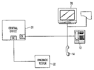
Referring to the simplified diagrammatic illustration of a
telephone network in Figure 1, a ringback test device 10
within a telephone network central office 16 is accessible
by a subscriber's handset 12 or a craftsperson's test set
14, in order to 'ring back' the caller's telephone number
after the caller goes on hook. This ringback operation
serves to verify continuity and operation of dial-up lines
between the telephone central office and the caller, thus
providing a relatively complete test of a circuit from the
caller's connection through the PSTN circuit, including
2
CA 02489782 1997-05-14
office equipment (oE) in the telephone central office
capable of providing telephone service and back to the
caller's connection.
one type of prior art ringback test device employed
for this purpose is described in the U.S. Patent 4,764,949
issued August 18, 1988 to Richard Faith, et al.
(hereinafter referred to as the '949 patent), assigned to
the assignee hereof, and the disclosure of which is
incorporated herein. The ringback test device of the '949
, patent is designed to address the fact that a caller, such
as a craftsperson working on the line with a butt-in test
set, or a telephone equipment installer, for example, may
not know the telephone number associated with the line from
which the call to the central office facility is being
placed.
This problem is eliminated by the test device of the
'949 patent, which is operative to provide the caller's
telephone number, in response to the caller calling a
prescribed ringback access code, which accesses the
ringback test device 10 at the telephone central office.
Upon receipt of the ringback access code, the test device
10 signals a specialized trunk facility 18 within the
telephone central office 16, known as a toll trunk or
outgoing trunk circuit, causing it to transmit a message
that identifies the caller's telephone number. This number
is then stored at the ringback test device 10 and the
caller is instructed to disconnect from the circuit (go on
hook). Once the caller goes back on-hook, the test device
3
CA 02489782 1997-05-14
sends a signal to the central office 16 instructing it
to dial the stored telephone number. If the caller s
telephone rings, the ringback test is considered
successful.
5 Now although the scheme described in the 1949 patent
provides for ringback testing, it suffers from the fact
that toll trunks are costly and may not always be available
for testing purposes. Unless a test device has been
installed with the toll trunk equipment- in the central
10 office, ringback testing cannot be conducted. Moreover,
because a toll trunk is involved, its operation may result
in toll charges associated with use of someone else~s
(e.g., the phone company) tester. In addition, a
substantial amount of AC and DC signaling is necessary in
order to obtain the calling party information through this
type of interface.
To obviate this shortcoming, the X698 application
describes a processor-based ringback testing scheme,
diagrammatically shown in Figure 2, which takes advantage
of out-of-band signaling system protocol Signal System 7
(SS7) employed in caller identification (caller ID) class
of service information currently provided by the telephone
network during the four second silent interval between the
first~and second rings of the called subscriber s telephone
number.
4
CA 02489782 1997-05-14
The caller ID information contains the caller's
telephone number, time of call, caller's name, and other
information in a signal that is transmitted from the
central office to a called subscriber during the four
second silent interval between the first and second rings
of the called subscriber's telephone. (For detailed
information on caller ID signalling, attention may be
directed to Bellcore Technical Reference TR-TSY-000031,
Issue 3, January 1990 (Bellcore, Morristown, NJ).
, More particularly, in the improved ringback testing
scheme of the '698 application, shown in Figure 2, a
caller's telephone 12 or 14 is connected to the telephone
central office 16 through a telephone network, and to a
test device 22. Unlike the test device 10 in the toll
trunk-dependent system of Figure 1, the test device 22 may
be installed in an equipment bay at a telephone central
station, or it may be portable and connected to the
telephone network using a standard telephone connection.
The test device 22 is assigned a telephone number so that,
in effect, it becomes a subscriber in the telephone
network.
Operation of the test device 22 is initiated by a call
being placed from the caller's telephone 12 or 14 to the
telephone number assigned to the test device. When the call
has been switched to it, the test device detects and stores
the caller ID information and, after the second ring, goes
off hook - completing the connection to the caller's
telephone. The test device then 'plays back' the detected
5
CA 02489782 1997-05-14
and stored caller ID number to the caller, using a voice
synthesizer to audibly "speak" the identified telephone
number to the caller. The caller is instructed to go back
on-hook, so that the test device 22 may place perform a
ringback test by dialing the stored caller ID telephone
number.
In addition the telephone number, per se, and/or name
identified in the caller ID information, the test device
may store other information that the caller may selectively
, retrieve, such as numbers entered manually by the caller
from the caller's telephone, thereby enabling the test
device to call other telephone numbers at the discretion of
the caller, or used for further tests. The test device is
further operative to provide a modem-sourced data session
with caller equipment that employs a visual user interface,
such as a video screen, printer, or data terminal, for
viewing display-formatted caller ID and other information.
This capability is particularly useful when a large number
of ringback tests are being conducted and a record of such
tests is desired. Also it enables a craftsperson to perform
tests on the called circuit other than ringback, such as
checking the caller ID by verifying that the detected
caller ID information identifies the correct telephone
number (in the event the caller's telephone number is
known), or to validate a craftsperson's dispatch trouble
6
CA 02489782 1997-05-14
ticket information relative to the subscriber's telephone
number. The test device of the '949 application can also be
used to verify that caller ID is properly coded for
unlisted telephone numbers.
Now although the ringback test device described in the
'698 application detects and stores caller ID information
for subsequent use, including ringback testing, as
described above, it does not address the testing of recent
caller identification-related additions to the CLASS
, feature set - most notably ' Caller Identification with Call
Waiting' (CIDCW). CIDCW is defined in Bellcore document TA-
NWT-000575 and may be summarized as follows.
If a subscriber who is engaged in an active telephone
call has the CIDCW feature enabled and receives an
additional incoming call, the subscriber will receive a
subscriber-alerting-signal identical to the standard call-
waiting tone. Following this initial alerting signal, the
subscriber's phone set or other customer premises equipment
(CPE) will receive a CPE Alerting Signal (CAS) from the
central office switching equipment using the above-
referenced Signaling System 7 (SS7) network. This CAS
signal prepares the CPE device, such as a Caller ID desk
top display unit or display telephone, to receive the
Caller ID data associated with the second caller. If the
CPE is working and ready to receive the Caller ID
7
CA 02489782 1997-05-14
information, it will respond to the central office
switching equipment with an acknowledgement signal, after
which the switching equipment will transmit the Caller ID
information in accordance with the industry standard format
described in Bellcore document TA-NWT-000030.
Attendant to the introduction of CIDCW is the desire
by telephone service providers to test this service in a
manner that can also take advantage of out-of-band
signaling system protocol Signal System 7 (SS7) employed in
l0 the caller identification (caller ID) class of service
information, as does the test device described in the
above-referenced '698 application.
SUMMARY OF THE INVENTION
The present invention addresses this need by providing
a multiple port ringback test unit through which a
telephone craftsperson can independently and through his
own actions receive two concurrent complete telephone calls
through the public switched telephone network (PSTN) upon
demand. The invention allows this functionality to be
provided even when the craftsperson does not know the
telephone number from which he is calling.
As will be described, the multiple port ringback test
unit of the present invention includes a first
communication port (associated with voice channel
signalling) and a second communication port (associated
with either voice or data channel signalling). Each port
has its own assigned telephone number and is coupled to a
8
CA 02489782 1997-05-14
call supervision computer-controlled transceiver. Such
multi-port signalling capability, which is used in the
course of testing the ability of the telephone circuit to
exercise caller identification and call waitinct class
(CIDCW) of service, as will be described, enables the
present invention to place multiple return telephone calls
to a subscriber number identified through the Caller ID
data.
The test unit's transceiver includes a respective ring
detector for each of the two telephone numbers, and
respective line interface circuits and associated hybrids
that are coupled to a processor-controlled modem. In
addition, each communication port is selectively terminated
by way of the same AC termination impedance, which is
controllably inserted into the incoming line to terminate
the caller ID signalling channel. All dual tone
multifrequency (DTMF) command control is maintained
exclusively through the first communication port. Command
control is not accessible from the second communication
port. Therefore, when a disconnect at the first
communication port occurs - either intentionally or
accidentally - the invention discontinues all active
callbacks, regardless of which line they are on and drives
all phone lines to the inactive (on-hook) state. The call
supervision computer is programmed to cause the
9
CA 02489782 1997-05-14
communication transceiver to interface signals that are
effective to test the operation of the calling party~s
telephone circuit by way of either or both of the first and
second communication ports.
In accordance with a first aspect of the multi-port
test unit of the present invention is operative to test the
ability of a telephone circuit installed in a telephone
network to properly exercise caller identification and call
waiting class (CIDCW) of service. For this purpose, in
~ response to receiving and answering an incoming call
directed to a first of its communication ports, the test
unit is operative to detect and store the telephone number
assigned to the calling telephone circuit, which number is
contained in caller identification information provided by
the telephone network. Tn particular, the inventive test
unit captures and stores Caller Number and/or Name and Time
of Delivery data upon access. It then issues a series of
synthesized voice prompts associated with menu options
available to the calling party.
In response to caller reply action to these
synthesized voice prompts, such as the calling party using
a phone keypad to enter prescribed menu-based response
tones representative of conducting a test of the CIDCW
feature of the calling telephone circuit, and initiates
prescribed action by the test unit, the test unit prompts
the calling party to hang-up (go back on-hook), and then
places a first outgoing call by way of the first
communication port to the telephone number that has been
CA 02489782 1997-05-14
detected (and stored) as being assigned to the telephone
circuit that placed the call to the test device, whether
that call was placed from a craftsperson's test set or CPE.
To this end, once the calling party hangs up, the test
unit drives the telephone line connected to its first
communication port off-hook, and monitors the line for dial
tone, whereupon it proceeds to dial (via DTMF signalling)
the number associated with the Caller ID data. When the
called telephone circuit is called, caller ID information
, is provided to the calling party, for example by way of a
voice announcement of the calling number associated with
the telephone number assigned to the first communication
port of the test unit, and/or a display of that number by
way of an attendant display unit, either integrated in the
telephone set coupled to the subscriber's line circuit or
by way of a separate display unit.
When the telephone unit coupled to the subscriber's
line circuit (e. g., craftsperson test set or subscriber
unit) answers this first callback or ringback, placed from
the test unit, testing of the CIDCW class of service of the
called telephone circuit is invoked by the test unit by
placing a second outgoing ringback or callback, using its
second communication port to the number assigned to the
subscriber's line circuit.
As a result of the first callback having already been
established and causing the subscriber's telephone circuit
to be busy, the second callback serves the purpose of
exercising the called telephone circuit's Caller ID
11
CA 02489782 1997-05-14
function for the Call Waiting environment. As in the case
of the first callback, if the CPE is display-equipped, the
caller TD for call waiting feature will be detected and
displayed for viewing by the craftsperson, so that
operation of the circuit's response may be visually
monitored.
In addition, call progress tone monitoring may be
performed on both callback lines in order to determine the
state of each callback. Once both callbacks are completed,
the craftsperson has several call treatment options,
including: 1- putting the first outgoing call from the test
device to the subscriber circuits number on hold, while
answering the second call; 2- ignoring the second call as
with standard call-waiting; and 3- connecting both calls
together in a conference arrangement. In the latter
instance, the multi-port test unit of the present invention
is operative to assert an identification tone on the second
callback line, once it has been determined that the call
has been answered. This line-two identification tone is
maintained until the second line is driven on hook, and
allows the technician, and possibly customer, to make the
distinction between calls placed via the first and second
communication ports.
During the course of validating Caller Name and Number
Delivery to a subscribers telephone set, a telephone
craftsperson is required to perform several tasks, which
may be divided into two general functions or sets of
functions. The first function involves testing the
12
CA 02489782 1997-05-14
telephone network s ability to properly forward the
subscriber's information, either phone number or phone
number and directory name listing, to the party being
called by the subscriber. In some cases the appropriate
information is a message indicating that the calling
subscriber s number is unlisted and hence marked ~~private~~
for Caller Identification purposes. Further, the telephone
line may or may not be capable of carrying the frequency
shift keyed data required for Caller ID data transfer in
, which case a «data error~~ message may be displayed, in lieu
of Caller ID data.
As pointed out above, the first feature of the present
invention uses its mufti-port signalling capability in the
course of testing the ability of the telephone circuit to
place multiple return telephone calls to a subscriber
number identified through the Caller ID data, and thereby
exercise caller identification and call waiting class
(CIDCW) of service.
In accordance with a further feature, the service
technician accessing the test unit of the invention may
override the subscriber number identified by the Caller ID
data and enter a different number from a standard DTMF
(touch-tone) telephone or test set. Utilizing the
alternative method offers the user the flexibility of a
testing line other than the one used to access the test
unit. This is of particular importance in situations where
more than one telephone number is associated with a
residence or business.
13
CA 02489782 1997-05-14
For instance, a home equipped with the distinctive
ringing class of service offered by its local telephone
service provider, in which telephone calls to a primary
number invoke a standard ringing cadence, while calls to
the same residence, but to a different phone number, such
as those intended for a "business" or "teen" line cause the
same phones to ring but using a different audible ringing
cadence, in order for the customer to determine for whom
the incoming call is intended simply by the listening to
~ the cadence of the ringing signal. For business
applications, this feature of the invention may be utilized
for making a particular line or trunk in a "rotary/hunt"
group ring.
In this environment a call placed from a business
phone may be routed through one of several different
outgoing trunks, each with a differently assigned telephone
number. With its caller ID detection and storage feature,
the test unit of the present invention is operative to
determine the phone number of the single trunk that was
chosen to make the access call. The choice of any one of
the specific outgoing trunks available in a business is
generally not made by the caller, but rather the telephone
switching system or PBX system. Therefore, in order to
effect a callback on a specific numbered trunk, the
technician must be allowed to override the Caller ID data
and manually enter the number to which the return telephone
call is to be placed. It is to this requirement that the
Caller ID override feature of this invention is addressed.
14
CA 02489782 1997-05-14
In addition to conducting the foregoing operations,
the craftsperson may employ the second port to conduct a
modem-based data session with a complementary data unit
coupled to the subscriber's line circuit. As mentioned
above, whenever an call is directed to the test unit,
whatever tone-encoded, caller associated information is
contained in the incoming ringing signal is received and
stored by the test unit. Since the contents of this encoded
information may involve considerably more than simply the
~ calling party's number, such as the name and/or address of
the caller, time of day, etc., playback of such information
is not practically realized using a voice synthesizer.
However, such information is readily downloaded to a data
device coupled to the subscriber's line circuit, by
establishing a data link with the test unit. The second
communication port and the modem provided in the test unit
serve to provide this functionality.
Pursuant to a further "Call Return" feature, the test
unit of the invention is operative to cause a call to be
returned to a calling telephone circuit and thereby test
that circuit's ability to receive incoming calls, even
through the caller ID detection and storage functionality
of the invention cannot be exercised on the incoming call,
for example, in the case where access to such caller ID
information normally provided by the telephone network has
been restricted or 'masked'. This feature of the invention
CA 02489782 1997-05-14
takes advantage of the fact that whenever any network
subscriber places a call to another (called) subscriber,
the central office switching equipment keeps a temporary
record of the called number.
More particularly, if for any reason a called
subscriber does not, or cannot answer the call when it
comes in, he may use what is known as a Call Return class
of service of the central office switching equipment to
place a return call to the original caller, even though the
identity of the calling party is unknown. In order to
invoke the call return class of service, the called party
goes off-hook and dials the Call Return code (usually *69)
prior to placing another phone call. The telephone
network's switching equipment will then place a return call
to the original calling telephone circuit just as if it
were dialed normally.
The Call Return feature of the test unit of the
present invention basically emulates this routine by
hanging up and then dialing the Call Return code at the
craftsperson's request to do so in reply to a voice menu
prompt. Then, at the telephone number to which the
craftsperson's equipment is coupled, incoming or 'return'
call to the telephone circuit is monitored for the presence
of caller ID information identifying the telephone number
of the test circuit test device. Although the default
dialing code to invoke Call Return is *69, this code is
programmable and can be changed to support various local
telephone company standards. A user mode menu item is
16
CA 02489782 1997-05-14
employed to invoke this feature and the voice prompt
indicates the appropriate dial code function to invoke
"CALL RETURN".
In accordance with an additional 'Message Waiting
Indicator' test feature of the invention, the test unit is
controllably operative to readily validate the status and
state of service for a Message Waiting indicator, such as
lamp or message on a display screen provided on some caller
ID equipment (or an audible signal for the visually
impaired) that is normally turned on if a voice message is
,
waiting for the phone number to which the equipment is
connected, and then turned off when the user of the feature
accesses indicated messages.
The problem being addressed is the unfamiliarity of
the customer of a telecommunications device with the
operation of a telephone network. The customer does not
realize that background operations such as update-polling
of auxiliary devices, including message-waiting indicators,
are low priority tasks, and are therefore not conducted at
the same frequency as more important tasks, such as
providing dial tone - the primary function of the network's
office equipment. Indeed, it is not uncommon for the
setting or turning ON of message waiting indicator lights
of various customer equipments to be conducted at a polling
rate on the order of every quarter hour, and the resetting
or turning OFF of message waiting indicator lights to be
conducted at a polling rate on the order of once per hour.
17
CA 02489782 1997-05-14
Since the unitiated customer does not know this, the
customer will infer that the device is defective, for
example in the case that the message waiting indicator does
not turn off immediately after the customer has accessed
and cleared a voice mail message, or if the customer is
queried during a voice conversation with another party
whether the customer has received a voice mail message that
the other party had sent, yet the message indicator light
has not been on. In such circumstances it is not uncommon
for the customer to call the network service provider and
complain that the message waiting function is not working
properly. The test functionality of the routine of the
present invention allows a craftsperson to test the
operation of the customer's message waiting indicator,
while the customer is off-hook and without having to burden
the central office equipment.
The conventional method of determining whether such a
message waiting service is operating properly requires that
a message be left, followed by a waiting period of time,
during which the central office switching equipment will
send a data message to the CPE equipment indicating that a
message is present. Upon receipt of this message from the
central office equipment, the CPE equipment will energize
the message waiting indicator. In the absence of a waiting
message, the CPE equipment is expected to turn off the
message waiting indicator in order to accurately inform the
user that no messages are pending. Both of these operations
are slow and inefficient.
18
CA 02489782 1997-05-14
To remedy this problem, the 'Message Waiting
Indicators test feature of the invention provides a user
with a voice-prompted menu, from which specific functions
are selectable, so as to allow the test unit to send, upon
user demand, either a "message Waiting Activate" or a
"Message Waiting De-Activate" signal to the CPE equipment.
Using this feature, the craftsperson, (or even the
subscriber) may invoke a test, which immediately tests the
ability of not only the CPE equipment to properly display
Message Waiting Status properly, but also the central
office switching system's ability to send the appropriate
data concerning Message Waiting. This real time information
allows a repair technician to determine the cause of
erroneous signaling directly from the field or customer's
location without requiring the services of additional
network personnel.
When the craftsperson operates the keypad of the test
set to enter either a request to turn the message waiting
indicator ON, or a request to turn the message waiting
indicator OFF, a visual message waiting indicator (VMWI)
flag is set or cleared. A prompt is issued to the user to
block the coupling of acoustic signals into the user's
telephone, so as to prevent potential corruption of the
transmission of a message waiting indicator control
message. In response to this prompt the user may either
operate a mute switch on the user's phone or cover the
telephone mouthpiece.
19
CA 02489782 1997-05-14
After a prescribed delay, the test set's modem is
configured for transmission of an FSK message. Based upon
the state of the vMWI flag, the transmit buffer is loaded
with a message representative of a request to turn the
message waiting light ON/OFF. In order to accommodate the
case where the user's device contains only a single message
waiting light, or further includes an auxiliary display,
such as an LCD alpha numeric capable visual display used
for caller ID messages, the encoded data stored in the
transmit buffer will contain a respective instruction
associated with each type of indicator configuration.
Each packet includes a single message data sequence
(SMDF) for the case of a user device having only a message
waiting indicator light, and a multiple message data
sequence (MMDF) for the case of a user device having
multiple message visual indication capability. As a data
throughput safeguard, the transmit data buffer is loaded
with a redundant copy of the encoded message. The
transmitter is then enabled, and the contents of the
transmit buffer containing the message are transmitted to
the user device.
In response to receiving and decoding the message
transmitted, the user's device changes the state of the
message waiting indicator. Then an advisory "message
complete" prompt is sent to the user, indicating that the
message waiting indicator confirmation operation is
finished. If the user's device is operating properly, the
message waiting indicator light will have changed state.
CA 02489782 1997-05-14
BRIEF DESCRIPTION OF THE DRAWINGS
Figure 1 is a diagrammatic illustration of a
simplified telephone network having a ringback test circuit
provided at the central office;
Figure 2 is a diagrammatic illustration of an
embodiment of a single-port ringback testing device
described in the above-referenced X698 application;
Figure 3 is a diagrammatic illustration of an
embodiment of a multi-ported testing unit in accordance
with the present invention;
Figure 4 is a flow chart of respective steps of a
CALLER ID, CALL-WAITING TEST using voice and data
communication ports of the multi-ported test unit of Figure
3;
Figure 5 is a flow chart of respective steps for a
MODEM DATA SESSION using a data communication port of the
multi-ported test unit of Figure 3;
Figure 6 is a flow chart of respective steps for
invoking a CALL RETURN from the test unit of Figure 3;
Figure 7 is a flow chart of respective steps for a
MESSAGE WAITING INDICATOR TEST using a voice communication
port of the multi-ported test unit of Figure 3;
Figure 8 is a flow chart showing details of steps 715
and 717 of Figure 7; and
Figure 9 shows non-limiting examples of encoding
sequences associated with the flow chart of Figure 8.
21
CA 02489782 1997-05-14
DETAILED DESCRIPTION
Before describing in detail the new and improved
multi-port ringback test unit of the present invention, it
should be observed that the invention resides primarily in
what is effectively a prescribed arrangement of
conventional communication circuits and associated signal
processing components. Consequently, the configuration of
such circuits components and the manner in which they are
interfaced with other communication network equipment have,
for the most part, been illustrated in the drawings by
readily understandable block diagrams, which show only
those specific details that are pertinent to the present
invention, so as not to obscure the disclosure with details
which will be readily apparent to those skilled in the art
having the benefit of the description herein. Thus, the
block diagram illustrations are primarily intended to show
the major components of the system in a convenient
functional grouping, whereby the present invention may be
more readily understood.
Referring now to Figure 3, an embodiment of a multi-
port testing unit in accordance with the present invention
is diagrammatically illustrated as comprising a first
(voice channel) communication port 101 coupled to tip and
ring conductors of a first line circuit 103, and a second
(data channel) communication port 201 coupled to tip and
ring conductors of a second line circuit 203. These
respective communication ports 101 and 201 are coupled to
transceiver circuitry which includes ring detectors 105 and
22
CA 02489782 1997-05-14
205 for each of two telephone numbers assigned to the test
unit, and respective line relay interface circuits 107 and
207. Ring detectors 105 and 205 are ported to a
communication control processor 300. To avoid cluttering
the drawings, connection links between the control
processor 300 and respective components with which it is
interfaced have, for the most part, not been shown in
Figure 3.
As described briefly above, and as will be detailed
below with reference to the flow charts of Figures 4 - 7,
the communication control processor 300 is programmed to
cause the test unit of Figure 3 to interface signals that
are effective to test the operation of a calling party's
telephone circuit by way of either or both of the first and
second communication ports 101 and 201.
The transceiver circuitry of the test unit of Figure
3, to which of communication ports 101 and 201 are coupled,
further includes switch contacts of a processor-controlled
relay 301 to a (600 ohm) off-hook AC termination impedance
303, which is controllably inserted by the test unit's
control processor across tip and ring during reception of
caller ID FSK signalling information between the first and
second rings of an incoming call. AC termination impedance
303 is selectively bridged across tip and ring lines 311
and 313, to which one of the tip and ring pairs of the
respective line circuits 103 and 203 is controllably
connected, by way of the switch contacts of relay 301.
23
CA 02489782 1997-05-14
Lines 311 and 313 are coupled to a differential
amplifier 321, the output of which is coupled through
bandpass filter 323 to a switch terminal 122 of a
processor-controlled switch 120 (S1). Filter 323 is tuned
to pass the FSK caller ID information contained in an
incoming call. Switch 120 has its common terminal 124
coupled to a data input port 131 of a modem unit 130,
having a digital data port 133 ported to communication
control processor 300. Processor-controlled switch 12o has
a switch terminal 121 coupled via link 141 to an output 152
of a dual hybrid unit 150, and a switch terminal 123
coupled via link 143 to an output 252 of a dual hybrid unit
250. Hybrid unit 150 has a bidirectional port 153 coupled
to processor-controlled line relay interface circuit 107.
Hybrid 150 has an input 151 coupled via line 154 to a
speech synthesizer 171, which is controlled by processor
300 to generate voice menu instructions to a calling port
accessing the test unit.
Link 141 is further coupled to a DTMF detector 140,
which is ported to control processor 300, and is employed
to maintain all dual tone multifrequency (DTMF) command
control exclusively through the first communication port
101. No command control is accessible from the second
communication port, so that when a disconnect at the first
communication port 101 occurs, all active callbacks are
discontinued, regardless of the communication port to which
they are coupled, an all phone lines are driven to the
inactive (on-hook) state.
24
CA 02489782 1997-05-14
Line 154 is further coupled to a first switch terminal
221 of a processor-controlled switch 220 (S2), and to a
first switch terminal 321 of a further processor-controlled
switch 320 ( S3 ) . Switch 320 has a second switch terminal
322 coupled over line 254 to input 251 of dual hybrid unit
250. Switch 220 has its common terminal 224 coupled to the
data output terminal 132 of modem unit 130. Line 254 is
further coupled to a second switch terminal 222 of switch
220. Dual hybrid unit 250 has a bidirectional port 253
coupled to line relay interface circuit 207. Switch 320 has
its common terminal 324 coupled to a tone source 260. As
will be described, tone source 260 controllably sources
busy tone to a calling party via one of the communication
ports if the test unit is already engaged with a call on
the other communication port.
CA 02489782 1997-05-14
OPERATION
The operation of the test unit of Figure 3 will now be
described with reference to the flow charts of Figures 4'7,
which show the respective steps of communication exchange
sequences between a calling party, such as a craftsperson's
test set, used to access the test unit of the invention.
CALLER ID, CALL-WAITING TEST (Figure 4)
As pointed out above, in order to test the caller
identification and call waiting class (CIDCW) of service of
a (subscriber's) telephone circuit, a call is placed from
a telephone unit, such as a craftsperson's test set or CPE,
that is coupled to the telephone circuit, usually at the
customer premises. For this purpose, the craftsperson dials
into the test unit of Figure 3, as by dialing the telephone
number associated with its communication port 101, as shown
at step 401 in the flow chart of Figure 4. When the
incoming ringing tone is detected (step 403), ring detector
105 provides an output to the control processor 300
advising the test unit of the presence of an incoming call.
In query step 405, a determination is made as to
whether the test unit is already engaged with a call on the
other communication port ( port 201 in the present example ) .
If the answer to query step 405 is YES, processor 300
causes a busy tone to be returned in step 406 from tone
source 260 via switch contact 321 of switch 320 to the
input 151 of hybrid unit 150. The busy tone is coupled
thereby through line relay interface unit 107 to port 101.
26
CA 02489782 1997-05-14
However, in the present example, it will be assumed that
the answer to query step 405 is NO ( the test unit is not
currently involved in another call via communication port
201), so that the test unit may proceed to answer the call.
Next, in step 407, communication control processor 300
operates relay circuitry within the line transformer/relay
unit 107, so as to maintain the switch contacts of relay
301 defaulted to termination impedance 303, via relay
contacts 304, which are also closed, so that the FSK-
encoded signal is properly terminated by the 600 ohm AC
termination impedance 303. Control processor 300 also
operates switch 120, so as to couple terminal 123 to the
data input 131 of modem 130. As a result, whatever caller
ID information (e.g., Caller Number and/or Name and Time of
Delivery data) is contained between the first and second
.rings tones of the incoming call is output from
differential amplifier 321 through filter 323 to the data
input 131 of modem 130, from which it is coupled to and
stored in processor memory, as shown at step 409.
When the incoming call to the first communication port
101 is answered (step 411), control processor 300 uses
speech synthesizer 170 to issue a series of synthesized
voice prompts associated with menu options available to the
calling party, as shown in step 413. Such voice prompts may
include a request that the calling party enter a ~password~
(by way of keypad-sourced DTMF signals), to start the test.
The user then proceeds to enter further caller reply-
sourced DTMF tones associated with a CIDCW test and
27
CA 02489782 1997-05-14
selected in accordance with the voice menu provided to the
caller) in step 415. As DTMF tones are received decoder 140
provides output signals to the processor 300. Next, in step
417, control processor 300 prompts the calling party to
hang-up (go back on-hook).
When the test processor detects that the calling party
has gone back on-hook in step 419, then in step 421, the
test unit drives the telephone line 103 connected to its
first communication port 101 oft-hook, and monitors the
line for dial tone, whereupon it proceeds to dial (via DTMF
signalling via modem 130) the number associated with the
Caller ID data it has stored from the previous incoming
call, as shown at step 423.
In particular, control processor 130 places a first
outgoing call by way of the data output terminal 132 of
modem 130 through the switch terminal 121 of switch 120, to
the input 151 of hybrid unit 150. Hybrid unit 150 outputs
the first callback or ringback through the line
transformer/relay unit 107 to the first communication port
101, for transmission to the telephone number previously
detected ( and stored ) as being assigned to the telephone
circuit that placed the call to the test unit. This first
ringback call will contain the caller ID information
associated with the telephone number assigned to the first
port 101 of the test unit, so that the calling party will
be advised, via whatever caller ID output device is coupled
to the subscriber's line circuit, that the number it
previously called to invoke the CIDCW test has called back.
28
CA 02489782 1997-05-14
As pointed out previously, this caller ID information
may be provided to the calling party by way of a voice
announcement of the calling number associated with the
telephone number assigned to the first communication port
of the testing unit, and/or a display of that number by way
of an attendant display unit, either integrated in the
telephone set coupled to the subscriber's line circuit or
by way of a separate display unit. When the telephone unit
coupled to the subscriber's line circuit (e. g.,
craftsperson test set or subscriber unit) goes off-hook in
answering this first callback or ringback from the test
unit, as shown by step 425, testing of the CIDCW class of
service of the called telephone circuit is invoked.
For this purpose, as shown by step 427, a second
outgoing ringback or callback of the telephone circuit of
interest is placed by processor 300, using the test unit's
second communication port 201. In placing this second
callback to the subscriber's circuit, the control processor
130 operates switch 120 to connect the data output terminal
132 of modem 130 through switch terminal 222 of switch 120,
and thereby to the input 251 of hybrid unit 250. Hybrid
unit 250 outputs the second ringback call through the line
transformer/relay unit 207 to the second communication port
201, for transmission to the same telephone number
previously detected (and stored) as being assigned to the
telephone circuit that placed the call to the test unit,
and called back by the first ringback call. Like the first
ringback call, the second ringback will contain caller ID
29
CA 02489782 1997-05-14
information associated with the test unit. Since a separate
telephone number is assigned to port 201, the caller ID
information in the ringback call from port 201 will contain
the telephone number assigned to the second port 201 of the
test unit, so that the calling party will be advised via
its caller ID output device of this second number.
Since the first ringback call has already been
answered by the subscriber's line circuit, that line
circuit is currently busy, so that the second callback
serves the purpose of exercising the called circuit's
Caller ID function for the Call Waiting environment. As in
the case of the first callback, assuming that the CPE is
display-equipped, the caller ID for call waiting feature
for the second line will be detected and displayed for
viewing by the craftsperson, so that operation of the
subscriber's circuit's response may be visually monitored
by the craftsperson.
Once both callbacks are completed as described above,
the craftsperson has several call treatment options, as
shown at step 429, including: 1- putting the first ringback
call from the test device to the subscriber circuit's
number on hold, while answering the second ringback call;
2- ignoring the second ringback call as with standard call-
waiting; 3- connecting both ringback calls together in a
conference arrangement; and 4- terminating the call. In
order to properly use the third option, the test unit is
operative to assert a 'callback progress' identification
tone on the second callback line, once it has been
CA 02489782 1997-05-14
determined that the call has been answered. This line-two
identification tone is maintained until the second ringback
line is driven on-hook, and allows the technician, or
customer, to make the distinction between calls placed via
the first and second communication ports 101 and 201.
In the CIDCw test routine described above, the caller
ID information in the incoming call accessing the test unit
is that associated with the telephone circuit from which
the call is placed. In accordance with a further feature,
l0 the service technician accessing the test unit of the
invention may override the subscriber number identified by
the Caller ID data, and enter a different number from a
standard DTMF (touch-tone) telephone or test set. Utilizing
this alternative method makes it possible to test a line
other than the one used to access the test unit. This is of
particular importance in situations where more than one
telephone number is associated with a residence or
business.
As a non-limiting example, a residence may be equipped
with the distinctive ringing class of service offered by
its local telephone service provider, in which telephone
calls to a primary number invoke a standard ringing
cadence, while calls to the same residence, but to a
different phone number, such as those intended for a
"business" or "teen" line cause the same phones to ring,
but with a different audible ringing cadence. These
separate or 'distinctive' rings enable the customer to
determine for whom the incoming call is intended.
31
CA 02489782 1997-05-14
For business applications, this feature of the
invention may be utilized for making a particular line or
trunk in a "rotary/hunt~~ group ring. Thus, a call placed
from a business phone may be routed through one of several
different outgoing trunks, each with a differently assigned
telephone number. Since the test unit detects and stores
whatever caller ID information is contained in the incoming
call, regardless of its source, it can determine the phone
number of the single trunk that was chosen to make the
l0 access call. The choice of any one of the specific outgoing
trunks available in a business is generally not made by the
caller, but rather the telephone switching system or PBX
system.
To effect a callback on a specific numbered trunk, the
craftsperson invokes an override of the Caller ID data via
his test set, and then manually enters the number to which
the return telephone call is to be placed. The sequence of
operations then proceeds as described above, with the
ringback calls being placed to the override number supplied
by the craftsperson.
MODEM DATA SESSION (Figure 5)
In addition to conducting the foregoing operations,
the craftsperson may employ the second communication port
201 of the test unit to conduct a modem-based data session
with a complementary data unit (e. g., data terminal unit
(DTE) or test set) coupled to the subscriber s line circuit
from which the call to the test unit is placed. As
32
CA 02489782 1997-05-14
mentioned above, whenever an call is directed to the test
unit, the tone-encoded caller ID information contained in
the incoming ringing signal is received and stored by the
test unit. Since the contents of this encoded information
may involve considerably more than simply the calling
party~s number, such as the name and/or address of the
caller, time of day, etc., playback of such information is
not practically realized using a voice synthesizer.
However, such information is readily downloaded to a data
device coupled to the subscriber s line circuit, by
establishing a data link with the test unit. The data
channel communication port 201 and the modem 130 provide
this functionality.
In order to establish a data session with the test
unit, the craftsperson dials into the test unit, by dialing
the telephone number associated with the second
communication port 201, as shown at step 501 in the flow
chart of Figure 5. When the incoming ringing tone is
detected (step 503), ring detector 205 provides an output
to the control processor 300 advising the test unit of the
presence of the incoming call. In query step 505, a
determination is made as to whether the test unit is
already engaged with a call on the other communication port
(port 101). If the answer to query step 505 is YES,
processor 300 causes a busy tone to be returned in step 506
from tone source 260 via switch contact 322 of switch 320
to the input 251 of hybrid unit 250. The busy tone is
coupled thereby through line relay interface unit 207 to
33
CA 02489782 1997-05-14
communication port 101. In the present example, it will be
assumed that the answer to query step 505 is NO (the test
unit is not currently involved in another call via
communication port 101), so that the test,unit may proceed
to answer the incoming call on port 201.
Next, in step 507, communication control processor 300
operates relay circuitry within the line transformer/relay
unit 207, so as to the switch the contacts of relay 301 to
line 203, so that the incoming call on port 201 will be
coupled to termination impedance 303, via relay contacts
304, which are also closed, whereby that the FSK-encoded
signal is properly terminated by the 600 ohm AC termination
impedance 303. Control processor 300 also operates switch
120, so as to couple terminal 123 to the data input 131 of
modem 130. Thus, the caller ID information (e. g., Caller
Number and/or Name and Time of Delivery data) contained
between the first and second ring tones of the incoming
call to communication port 201 is output from differential
amplifier 321 through filter 323 to the data input 131 of
modem 130, from which it is coupled to and stored in
processor memory, as shown at step 509.
When the incoming call to the second communication
port 201 is answered (step 511), control, processor 300
operates switches 120 and 220, to connect the respective
data input and output ports 131 and 132 of modem 130 to the
34
CA 02489782 1997-05-14
output and input ports 252 and 251 of hybrid 250, thereby
establishing a bidirectional data path between port 201 and
the modem, as shown at step 513, so that a data exchange
session between the calling party terminal device and the
test unit may take place, as shown at step 515.
The data session with the craftsperson is then
interactive, with instructions displayed on the caller's
data terminal or test device initially prompting the user
to enter a 'password' and, if accepted, to select from
~ specified menu choices or supply information for verify all
of the caller ID information, such as the spelling of a
subscriber's name. This interactive data session feature of
the invention obviates the practical inability of a voice
synthesizer to play back the substantial amount of caller
ID information contained that is detected and captured by
the test unit, which may include considerably more than
simply the calling party's number, such as the name and/or
address of the caller, time of day, etc.
CA 02489782 1997-05-14
CALL RETURN TEST (Figure 6)
As pointed out above, the placing of a call to the
test unit of the present invention to validate Caller Name
and Number Delivery to a subscriber's telephone set also
effectively tests the network's ability to properly forward
the subscriber's information (e: g, phone number or phone
number and directory name listing) to a party being called
(the test set) by the subscriber. In some cases, however,
the caller ID information may be restricted, so that the
information contained in the incoming call to the test unit
is a message indicating that the calling subscriber's
number is unlisted and hence marked "private" for Caller
Identification purposes. As a result the desired caller
identification information is not detected and stored.
Another possibility is that the telephone line is not
capable of carrying the frequency shift keyed data required
for Caller ID data transfer, in which case a "data error"
message may be displayed, in lieu of Caller ID data. In
either case, since the test unit cannot determine caller ID
information from the incoming call, it cannot use such
(missing) information to test the ability of the calling
telephone circuit to receive calls.
Pursuant to a further "Call Returns' feature, the
inventive test unit employs an alternative mechanism for
placing a 'ringback' call to the calling telephone circuit
and thereby test that circuit's ability to receive incoming
calls, even through the caller ID detection and storage
functionality of the invention cannot be exercised on the
36
CA 02489782 1997-05-14
incoming call, for example, in the case where access to
such caller ID information normally provided by the
telephone network has been restricted or 'masked', as
described above. This feature of the invention takes
advantage of the fact that whenever any network subscriber
places a call to another (called) subscriber, the central
office switching equipment keeps a temporary record of the
called number.
As described previously, in accordance with the Call
, Return class of service offered by the telephone network,
if a called subscriber does not, or cannot, answer an
incoming call, he may still successfully return the call by
dialing a specified Call Return code ( usually *69 ) prior to
placing another phone call. The telephone network's
switching equipment will then place a return call to the
original calling telephone circuit (whose number has been
temporarily stored), just as if it were dialed normally.
The Call Return feature contained in the test unit of the
present invention basically emulates the routine carried
out by the subscriber.
More particularly, as in the testing of the caller
identification with call waiting class (CIDCW) of service
of a (subscriber's) telephone circuit, described above, and
detailed in the flow chart of Figure 4, the craftsperson
dials into the test unit as by dialing the telephone number
associated with its communication port 101, as shown at
37
CA 02489782 1997-05-14
step 601 in the flow chart of Figure 6. When the incoming
ringing tone is detected (step 603), ring detector 105
provides an output to the control processor 300 advising
the test unit of the presence of an incoming call.
Again, in query step 605, a determination is made as
to whether the test unit is already engaged with a call on
the other communication port (port 201). If the answer is
YES, a busy tone is returned to port 101 in step 606.
Assuming that the answer to query step 605 is NO, the test
~ unit proceeds to answer the call.
In step 607, processor 300 operates relay circuitry
within the line transformer/relay unit 107, so as to
terminate the line to the AC termination impedance 303. It
also operates switch 120, so as to couple terminal 123 to
the data input 131 of modem 130, so that the caller ID
information contained in the incoming call is coupled to
the data input 131 of modem 130, from which it is coupled
to and stored in processor memory, as shown at step 609.
Since, in the present example, the caller ID
information does not reveal the calling party's telephone
number, when the incoming call to the port 101 is answered
(step 611) a voice prompt of this fact is issued (via
speech synthesizer 170) to the caller in step 612, who then
logs on by entering a ~password~ (by way of keypad-sourced
DTMF signals). The user may then enter further caller
38
CA 02489782 1997-05-14
reply-sourced DTMF tones associated with the call return
mode and selected from the voice menu provided to the
caller) in step 613. Next, in step 615, the processor
prompts the calling party to go back on-hook.
When the test processor detects that the calling party
has gone back on-hook in step 616, then in step 617, it
invokes the call return feature (e.g., by dialing *69) via
the called communication port ( 101 in the present example
) .
Although the default dialing code to invoke Call Return is
, typically *69, this code is programmable and can be changed
to support various local telephone company standards. In
response to the test unit invoking the call return feature,
the network then places a 'call return' ringback call to
the subscriber's telephone circuit, in step 619.
Since the caller ID information in the test unit is
unrestricted, the call return ringback call will contain
the caller ID information associated with the telephone
number assigned to the first port 101 of the test unit, so
that, in step 621, the calling party will be advised, via
whatever caller ID output device is coupled to the
subscriber's line circuit, that the call return operation
has been successful. (As noted above, this caller ID
information may be provided to the calling party by way of
a voice announcement of the calling number associated with
the telephone number assigned to the first communication
39
CA 02489782 1997-05-14
port of the test unit, and/or a display of that number by
way of an attendant display unit, either integrated in the
telephone set coupled to the subscriber s line circuit or
by way of a separate display unit.)
MESSAGE WAITING INDICATOR TEST (Figure 7)
In accordance with the Message Waiting Indicator
test feature of the invention, the test unit is employed to
controllably validate the operability of a Message Waiting
indicator, such as lamp or message on a display screen
provided on CPE caller ID equipment (or an audible signal
for the visually impaired), that is normally turned on if
a voice mail message is waiting for the phone number to
which the equipment is connected, and then turned off when
the user of the feature accesses indicated messages.
As described above, the conventional method of
determining whether such a voice mail message waiting
indicator is operating properly requires that a message be
left, followed by a waiting period of time, during which
the central office switching equipment will send a data
message to the CPE equipment indicating that a message is
present. Upon receipt of this message from the central
office equipment, the CPE equipment will energize the
message waiting indicator. In the absence of a waiting
message, the CPE equipment is expected to turn off the
message waiting indicator in order to accurately inform the
user that no messages are pending.
CA 02489782 1997-05-14
Because these operations are slow and inefficient, the
test unit of the invention incorporates a 'Message Waiting
Indicator' test mechanism which is invoked by way of the
voice-prompted menu presented to the caller at the
beginning of a call, as described above, and thereby allow
the test unit to send, upon user demand, either a "Message
Waiting Activate" or a "Message Waiting De-Activate" signal
to the CPE equipment. Using this feature, the craftsperson,
(or even the subscriber) may invoke a test, which
, immediately tests the ability of not only the CPE equipment
to properly display Message Waiting Status properly, but
also the central office switching system's ability to send
the appropriate data concerning Message Waiting. This real
time information allows a repair technician to determine
the cause of erroneous signaling directly from the field or
customer's location without requiring the services of
additional network personnel.
As described previously, as in the testing of the
caller identification with call waiting class (CIDCW) of
service of a (subscriber's) telephone circuit, and the use
of the call return feature, the craftsperson dials into the
test unit, by dialing the telephone number associated with
its communication port 101, as shown at step 701 in the
flow chart of Figure 7. When the incoming ringing tone is
detected (step 703), ring detector 105 provides an output
to the control processor 300 advising the test unit of the
presence of an incoming call. Assuming that the answer to
a busy query step 705 indicates that the test unit is not
41
CA 02489782 1997-05-14
already engaged with a call on the other communication port
(port 201), the test unit proceeds to answer the call.
Otherwise a busy tone is returned in step 706.
In step 707, the test unit's communication processor
operates relay circuitry within the line transformer and
relay unit 107, so as to terminate the line to the AC
termination impedance 303. It also operates switch 120, so
as to couple terminal 123 to the data input 131 of modem
130, so that the caller ID information (e. g., Caller Number
, and/or Name and Time of Delivery data) contained in the
incoming call is coupled to the data input 131 of modem
130, from which it is coupled to and stored in processor
memory, as shown at step 709.
When the incoming call to the first communication port
101 is answered (step 711), control processor 300 uses
speech synthesizer 170 to issue a series of synthesized
voice prompts associated with menu options available to the
calling party, as shown in step 713. Again these voice
prompts may include a request that the calling party enter
a 'password' (by way of keypad-sourced DTMF signals), to
start the test. The user then proceeds to enter further
caller reply-sourced DTMF tones associated with selection
of the desired message waiting indicator test from the
voice menu provided to the caller in step 715.
42
CA 02489782 1997-05-14
Depending upon the choice entered by the user
('message waiting indicator ON' or 'message waiting
indicator OFF'), the control processor will operate switch
220 to couple the data output port 132 of modem 130 to line
154, so that a prescribed FSK-formatted 'message waiting
indicator' control message sourced from the control
processor and coupled to modem 130 for transmission will be
asserted via the first communication port 101 to the
calling subscriber's unit, as shown by step 717. The user
~ may then monitor the response of the message waiting
indicator of the subscriber's unit to determine whether the
indicator is working properly.
For this purpose, as diagrammatically illustrated in
the flow chart of Figure 8, the craftsperson operates the
keypad of the test set to key in either a request to turn
the message waiting indicator ON in step 801, or a request
to turn the message waiting indicator OFF in step 802. If
the keyed-in request is to turn the indicator ON (step 801
asserted), the state of a visual message waiting indicator
(VMWI) flag is set to a first binary condition (e. g., '1')
in step 803. However, if the keyed-in request is to turn
the indicator OFF (step 802 asserted), the state of a
visual message waiting indicator (VMWI) flag is set to a
second binary condition (e. g., '0' or cleared) in step 804.
In step 805, the test set's microcontroller is
operative to transmit a prompt to the user to block the
coupling of acoustic signals into the user's telephone, and
thereby prevent potential corruption of the transmission of
43
CA 02489782 1997-05-14
a message waiting indicator control message. In response to
this prompt the user may either operate a mute switch on
the user s phone or cover the telephone mouthpiece. After
a prescribed time out or delay interval ( e. g. , one second) ,
as shown by step 807, the routine proceeds to configure the
test set's modem for transmission of a Bell standard 202,
FSK message (step 809).
Next, in query step 811, the routine examines the
state of the VMWI flag, the state of which was defined in
either step 801 or step 802. If the VMWI flag is set (the
answer to step 811 is YES), the routine transitions to step
813, wherein a transmit buffer is loaded with a message the
data contents of which are representative of the request to
turn the message waiting light ON. (Conversely, if the VMWI
flag is not set (the answer to step 811 is NO), the routine
transitions to step 814, wherein the transmit. buffer is
loaded with a message the data contents of which are
representative of the request to turn the message waiting
light OFF.
In order to accommodate the case where the user s
device contains only a single message waiting light, or
further includes an auxiliary display, such as an LCD alpha
numeric capable visual display used for caller ID messages,
the encoded data stored in the transmit buffer will contain
a respective instruction associated with each type of
indicator configuration. Non-limiting examples of data
packet encoding sequences associated with these two data
formats are shown in Figure 9 at 901 (to turn the indicator
44
CA 02489782 1997-05-14
light ON) and at 902 (to turn the indicator light OFF) in
Figure 9. Each packet includes a single message data
sequence (SMDF) for the case of a user device having only
a message waiting indicator light, and a multiple message
data sequence (MMDF) for the case of a user device having
multiple message visual indication capability. As a data
throughput safeguard, the transmit data buffer is loaded
with a redundant copy of the encoded message.
In step 815, the test set's transmitter is enabled,
, and the contents of the transmit buffer containing the
message assembled in step 813 are transmitted to the user
device. Once the transmit buffer is empty (the contents of
query step 817 is yes), the test set's modem is reset (step
819). In response to receiving and decoding the message
transmitted in step 815, the user's device changes the
state of the message waiting indicator, as shown at step
717 in Figure 7. In step 821, the test set's
microcontroller transmits an advisory "message completes'
prompt to the user, indicating that the message waiting
indicator confirmation operation is finished. If the user's
device is operating properly, the message waiting indicator
light will have changed state in step 813. In step 823, the
routine is complete and returns to the main menu.
As will be appreciated from the foregoing description,
through the addition of a second communication channel and
enhanced software, the caller ID-based test unit of the
present invention is able to augment the testing
functionality of the test device described in the above-
CA 02489782 1997-05-14
referenced X698 application, by incorporating all the above
described features into one device, that is accessible and
remotely controllable by a single telecommunications
technician. The test unit of the invention is not only
capable of determining the telephone number, subscriber
name and various other information associated with the
subscriber line used to access to the unit, but is
operative to conduct various tests of a telephone circuit
from which a call to the test device is placed, which
~ include exercising a call identification, call waiting
class of service, testing the ability of the telephone
circuit to receive incoming calls, and testing the
operation of a message-waiting indicator of a telephone
unit coupled to the telephone circuit.
While we have shown and described an embodiment in
accordance with the present invention, it is to be
understood that the same is not limited thereto but is
susceptible to numerous changes and modifications as known
to a person skilled in the art, and we therefore do not
wish to be limited to the details shown and described
herein, but intend to cover all such changes and
modifications as are obvious to one of ordinary skill in
the art.
46