Note : Les descriptions sont présentées dans la langue officielle dans laquelle elles ont été soumises.
CA 02490324 2004-12-15
VIBRATORY CONVEYOR DECK
Field of the Disclosure
This disclosure generally relates to vibratory process equipment and, more
particularly, to decks used in vibratory conveyors.
Background of the Disclosure
Vibratory conveyors are generally known in the art for transporting objects
using a vibratory force. Such conveyors typically include a deck or other
structure
that has a conveying surface which defines a path along which objects are
conveyed.
Depending on the application, the path defined by the deck may be straight,
curved,
inclined, declined, spiral, or other configuration.
The deck is typically constructed of plate steel. As a result, when viewed in
cross-section, the conveying surface defined by the deck is typically "flat"
across the
width of the deck. Stated alternatively, the conveying surface is
substantially linear
across its width.
While a flat deck is satisfactory for many applications, it may cause
unintended and undesirable results when used to convey certain objects. For
example,
when conveying generally cylindrical objects such as cam shafts along a flat
deck, the
objects may roll transversely across the width of the deck, and therefore are
not
located on the deck with any degree of certainty. In addition, the cylindrical
objects
may become oriented transversely across the deck, and therefore more easily
roll into
and possibly damage other objects on the deck.
Flat decks are also difficult to employ for certain path configurations. In a
spiral conveyor, for example, it is preferable to form the deck in a helicoid
shape. To
approximate the helicoid shape with flat plate steel, several bends such as
cross
-1-
CA 02490324 2004-12-15
crimps are typically formed in the deck. Such cross crimps, however, create
abrupt
changes in the pitch of the deck and cause the conveying surface to be non-
linear
across its width. Consequently, the cross-crimps create localized high wear
area and
non-uniform stresses in the deck. These problems are exacerbated during
thermal
expansion and contraction, which can be significant when the spiral conveyor
is used
- for heating or cooling of the objects being conveyed. In addition, the need
for cross
crimps or other bends in the deck increases manufacturing costs and makes
assembly
more difficult, especially for conveyors that are constructed as multiple sub-
assemblies that are mated together, such as for large conveyor sizes.
Brief Description of the Drawings
FIG. 1 is a side elevation view of a vibratory spiral conveyor constructed in
accordance with the teachings of the present disclosure.
FIG. 2 is an enlarged, partially schematic, sectional side view of the
conveyor
of FIG. 1.
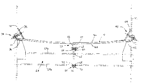
FIG. 3 is a plan view of the conveyor of FIG. 1.
F1G. 4 is an enlarged sectional side view of a portion of the conveyor deck
before the bending force is applied to the deck.
FIG. S is an enlarged sectional side view of a portion of the conveyor deck
with a bending force applied to the deck.
FIG. 6 is a plan view of a section of the deck.
-2-
CA 02490324 2004-12-15
Detailed Description
A conveyor deck is disclosed herein having a conveying surface and a back
surface. A rib is attached to the back surface and a "force assembly" is
coupled to the
rib. By applying a force to the rib with the force assembly, the deck may be
bowed
either concavely or convexly. If formed with a concave bend, the conveying
surface
of the deck, when viewed in cross-section, will have a localized low point
adjacent the
rib that defines a deck along which objects are conveyed. The concave shape
also
tends to orient cylindrical objects longitudinally on the deck, defined herein
as
parallel to the direction of travel. Additionally, when used in a spiral
conveyor, the
bowed cross-sectional shape allows the deck to be formed more nearly to a pure
helicoid, where the pitch of the deck is consistent along the entire conveyor
path and
each radial cross section of the deck will have linear opposing deck edges,
regardless
of whether the deck is curved concavely or convexly. While the disclosed
embodiment is a spiral conveyor, it will be appreciated that the bowed deck
shape
provides advantages for other conveyor path configurations, including linear,
curved,
and inclined paths.
Referring to FIGS. 1 and 2, a spiral conveyor 10 is shown having a frame 12
supporting a spiral deck 16. The frame 12 is resiliently supported above the
ground or
mounting surface by isolation means, such as springs 18. An exciter mass 20
and
vibration generators 22 are resiliently coupled to the frame 12, such as by
springs 21
(FIG. 2). Any generally known vibration generators may be used, such as motors
having rotating shafts carrying eccentric weights.
In the illustrated embodiment, the spiral deck 16 is oriented to vertically
elevate work pieces, such as hot castings, from an inlet 24 to an outlet 26.
The deck
16 defines a conveying surface 16a for receiving the work pieces and a back
surface
-3-
CA 02490324 2004-12-15
16b (FIGS. 4 & 5). The work pieces may be transferred from an origination
point,
such as a molding line, to the inlet 24 by any conveying means, such as by a
linear
vibratory or other type of conveyor (not shown). The spiral deck 16 is formed
in a
helical pattern so that, as the work pieces move circumferentially around the
deck,
they are also elevated in the vertical direction. When the conveyor 10 is
viewed in
elevational cross-section, as schematically shown in FIG. 2, the spiral deck
16 defines
a plurality of stacked tier segments 14. At the outlet 26, the work piece may
be
deposited onto an outlet transport (not shown), which may also be a conveyor.
While
the conveyor 10 is described herein as conveying the work pieces vertically
upward,
the inlet and outlet may be reversed so that the work pieces are conveyed
vertically
downward along the spiral deck 16.
The vibration generators 22 may be controlled in any known fashion to
produce the desired vibrational motion of the frame 12 and coupled spiral deck
16,
thereby to advance the work pieces along the deck 16. For example, the motors
may
be rotated in opposite directions (i.e., counter-rotated) and controlled to
maintain a
desired phase angle between the eccentric weights. While the illustrated
embodiment
is a two mass system, it will be appreciated that the conveyor 10 may be
provided as a
single mass or brute force system.
As best shown with reference to FIGS. 3-6, the spiral deck 16 includes an
inner edge 19 and an outer edge 21. An inner housing wall 30 is coupled to the
spiral
deck inner edge 19 and an outer housing wall 32 is coupled to the spiral deck
outer
edge 21. More specifically, the deck inner edge 19 is secured to the inner
housing
wall 30 by a first or inner wall support assembly 34, which may clamp the deck
inner
edge 19 between a bottom flange 36 and a top retainer 38 (FIG. S). Similarly,
the
deck outer edge 21 may be secured to the outer housing wall 32 by a second or
outer
-4-
CA 02490324 2004-12-15
wall support assembly 40, which may clamp the deck outer edge 21 between a
bottom
flange 42 and a top retainer 44. A plurality of access doors 46 (FIG. 1 ) may
be
formed in the housing outer wall 32 for accessing the different tier portions
14 of the
deck 16, should the outer housing wall 32 completely enclose the deck 16.
S A rib assembly SO is attached to the deck back surface 16b between the inner
and outer deck edges 19, 21 (FIGS. 4-6). The rib assembly may 50 may extend
continuously along the deck 16 in the longitudinal direction, so that, in the
illustrated
embodiment, the rib assembly has a spiral shape. The rib assembly 50 may
include a
pair of ribs 52 having aligned transverse apertures.
A force assembly 60 coupled to the rib assembly 50 to create a force that
bends the deck 16 into an arcuate shape when viewed in cross-section. The
exemplary force assembly 60 includes a pin 62 mechanically coupled to the rib
assembly 50, such as by insertion through the transverse apertures formed in
the ribs
52. A cross support 64 is spaced from the deck 16 and supported by the inner
and
1 S outer housing walls 30, 32. As shown, the cross support 64 is provided as
a tubular
steel member, and has apertures 65 formed in the upper and lower support
surfaces
64a, 64b. A link 66 is inserted through the apertures in the cross support 64
and
defines a first end 68 coupled to the pin 62 and a second end 70. The link 66
also
includes a threaded portion 72 for receiving a nut 74.
The nut 74 may be adjusted on the link threaded portion 72 to generate a force
in the link 66 that is transferred by the rib assembly 50 to the deck 16,
thereby to bend
the deck 16 in an arcuate shape. As shown in FIGS. 4 & 5, the nut 74 may be
located
below the cross support 64. In FIG. 4, the deck 16 is shown in a relaxed
state, where
the force assembly 60 applies no force to the deck 16. The nut 74 may be
adjusted
upwardly along the threaded portion 72 so that the nut engages the lower
surface of
-5-
CA 02490324 2004-12-15
the cross support 64, thereby to create tension in the link 66. The tensitm in
the link
66 is transferred by the pin 62 as a downwardly directed force acting against
the rib
assembly SO and attached deck 16. The nut 74 may be adjusted along the
threaded
portion 72 to create a tension force in the link 66 sufficient to bend the
deck 16 into an
S arcuate shape, as shown in FIG. S.
In an alternative embodiment, the pin 62 may be provided as a bar coupled to
the ribs 52 and formed with a threaded aperture. The link 66 may be a bolt or
threaded rod with the first end 68 threadably engaging the bar threaded
aperture. The
second end 70 of the bolt is a bolt head, which takes the place of the nut 74.
Accordingly, bolt may be threaded into the bar threaded aperture to create the
tension
force.
The ribs S2 may project sufficiently past the pin 62 to define stop ends 76
that
are engageable with the top surface 64a of the cross support, thereby to limit
the
amount of deflection of the deck 16. As shown in FIG. 4, when the deck 16 is
in the
1 S relaxed state, the rib stop ends 76 are spaced from the top surface of the
cross support
by a known distance "D". As the nut 74 is tightened to deflect the deck 16,
the stop
ends 76 are drawn toward and eventually engage the cross support top surface
64a,
thereby limiting the amount of deflection of the deck 16.
While the illustrated embodiment shows the deck conveying surface 16a bent
into a concave arcuate shape, the conveying surface may also be formed with a
convex arcuate shape. To do so, the force assembly 60 may be modified so that
the
link threaded portion 72 is adjacent an upper surface of the cross support 64,
and the
nut 74 may be adjusted downwardly along the threaded portion to engage the
upper
surface 64a of the cross support. Consequently, a compression force is
generated in
-6-
CA 02490324 2004-12-15
the link 66 that is transferred by the pin 62 as an upwardly directed force
against the
rib assembly 60 and attached deck 16.
To create the compression force in the alternative embodiment described
above, a nut may simply be provided on the bolt above the cross support upper
surface 64a, and the nut may be adjusted downwardly along the bolt to engage
the
upper surface 64a.
While only a single force assembly 60 is shown coupled to the rib assembly
60 in FIGS. 4 & 5, it will .be appreciated that a plurality of force
assemblies may be
coupled to the rib assembly 60 at points spaced along the longitudinal length
of the rib
assembly 50. In the segment of the deck 16 shown in FIG. 6, a total of three
force
assemblies 60 are shown coupled to the rib assembly 50. FIG. 6 also
illustrates the
ribs 62 extending along the longitudinal length of the deck 16. Furthermore,
while a
single deck segment is shown in FIG. 6, it will be appreciated that multiple
deck
segments may be fabricated independently and assembled to create the complete
conveyor deck. The improved fit of the arcuate shaped deck allows the ends of
the
deck segments to be more reliably located, thereby facilitating assembly of
mating
deck segments.
While a spiral conveyor path has been described and illustrated, the present
disclosure is applicable to other conveyor path configurations requiring
different deck
shapes, such as linear, inclined, or curved decks, while still providing some
or all of
the benefits described herein. Still further, multiple concentric (in the case
of curved
or spiral path configurations) or parallel (in the case of linear path
configurations) rib
assemblies may be attached to the deck 16 or adjacent sub-decks, each of which
having force assemblies coupled thereto, so that the deck is bent with
multiple arcs
defining multiple lanes for transporting a column of objects.
CA 02490324 2004-12-15
Although certain apparatus constructed in accordance with the teachings of the
disclosure have been described herein, the scope of coverage of this patent is
not
limited thereto. On the contrary, this patent covers all embodiments of the
teachings
of the disclosure fairly falling within the scope of the appended claims
either literally
or under the doctrine of equivalents.
_g_