Sélection de la langue

Search

Sommaire du brevet 2490496 

Énoncé de désistement de responsabilité concernant l'information provenant de tiers

Une partie des informations de ce site Web a été fournie par des sources externes. Le gouvernement du Canada n'assume aucune responsabilité concernant la précision, l'actualité ou la fiabilité des informations fournies par les sources externes. Les utilisateurs qui désirent employer cette information devraient consulter directement la source des informations. Le contenu fourni par les sources externes n'est pas assujetti aux exigences sur les langues officielles, la protection des renseignements personnels et l'accessibilité.

Disponibilité de l'Abrégé et des Revendications

L'apparition de différences dans le texte et l'image des Revendications et de l'Abrégé dépend du moment auquel le document est publié. Les textes des Revendications et de l'Abrégé sont affichés :

  • lorsque la demande peut être examinée par le public;
  • lorsque le brevet est émis (délivrance).
(12) Demande de brevet: (11) CA 2490496
(54) Titre français: MECANISME DE VERROUILLAGE JETABLE
(54) Titre anglais: DISPOSABLE LOCKING MECHANISM
Statut: Réputée abandonnée et au-delà du délai pour le rétablissement - en attente de la réponse à l’avis de communication rejetée
Données bibliographiques
(51) Classification internationale des brevets (CIB):
  • E21B 17/043 (2006.01)
  • E21B 17/046 (2006.01)
  • F16L 13/02 (2006.01)
(72) Inventeurs :
  • AIREY, PETER (France)
(73) Titulaires :
  • SCHLUMBERGER CANADA LIMITED
(71) Demandeurs :
  • SCHLUMBERGER CANADA LIMITED (Canada)
(74) Agent: SMART & BIGGAR LP
(74) Co-agent:
(45) Délivré:
(22) Date de dépôt: 2004-12-17
(41) Mise à la disponibilité du public: 2005-06-22
Licence disponible: S.O.
Cédé au domaine public: S.O.
(25) Langue des documents déposés: Anglais

Traité de coopération en matière de brevets (PCT): Non

(30) Données de priorité de la demande:
Numéro de la demande Pays / territoire Date
03293287.3 (Office Européen des Brevets (OEB)) 2003-12-22

Abrégés

Abrégé anglais


The invention concerns a locking mechanism for securing together a first and a
second part of a while drilling tool, said locking mechanism comprising a
first washer
designated to be fixed to said first part of the tool and a second washer
designated to be
fixed to said second part of said tool, said first and second washers being
welded
together in order to prevent any unwanted rotation between said first and
second parts.

Revendications

Note : Les revendications sont présentées dans la langue officielle dans laquelle elles ont été soumises.


4
CLAIMS
1. A locking mechanism (4) for securing parts (2, 3) of a while drilling tool,
said locking
mechanism comprising a first washer (40) designated to be fixed to a first
part (2) of
said tool and a second washer (41) designated to be fixed to a second part (3)
of said
tool, said first and second washers being welded (5) together in order to
prevent any
unwanted rotation between said first and second parts.
2. A locking mechanism according to claim 1, wherein said parts comprise a
threaded nut
(3) and the body (1) of the while drilling tool such that the first washer is
fixed to the
tool body and the second washer is fixed to the threaded nut.
3. A locking mechanism according to claim 1, wherein the parts comprise a
stabilizer (2)
and a nut (3) such that the first washer is fixed to said stabilizer and the
second washer
is fixed to said nut.

Description

Note : Les descriptions sont présentées dans la langue officielle dans laquelle elles ont été soumises.

CA 02490496 2004-12-17
Disposable locking mechanism
The invention relates to a disposable locking mechanism. More particularly,
the
invention provides a simple, cheap and very reliable means for locking a
threaded part on
the outside of a wireline tool, particularly a while-drilling tool, so that it
cannot be
unintentionally unscrewed.
In hydrocarbon exploration and production, it is of prime importance to
determine (a) if a given earth formation contains hydrocarbon, (b) the amount
of
hydrocarbon within the formation, and (c) the producibility of the hydrocarbon
in place
within the formation. The amount of hydrocarbon present within a formation is
a
function of the pore space or the "porosity" of the formation. In drilling
wells for the
production of hydrocarbon, and even after those wells have been drilled, it is
desirable to
measure the porosity of each prospective hydrocarbon producing formation
penetrated
by the borehole. It is even more desirable, for economic and operational
reasons well
known in the art, to determine the porosity of prospective formations during
the actual
drilling of the borehole.
Measurement-while-drilling (MWD) services were introduced commercially in
the 1970's. These systems were typically mounted within drill collars and
positioned as
close to the drill bit as possible. Early MWD systems were directed toward the
measurement of critical drilling parameters such as weight and the torque on
the drill bit
and direction of the drilled borehole. The operational and commercial value of
such
measurements is well known in the art. Subsequently, systems which measured
formation characteristics were introduced. Since such measurements provide
information
similar to wireline logging measurements, they are commonly referred to as
logging-
while-drilling (LWD) systems. There are many advantages in measuring formation
parameters while drilling the borehole, rather than after the borehole has
been drilled.
The operational, financial, and technical advantages of LWD are likewise well
known in
the art.

CA 02490496 2004-12-17
2
Many while-drilling tools have external threaded parts which are exposed to
high
frictional, thermal, shock and vibrational loads. These loads can cause the
parts to
unscrew and fall off. Falling of those parts in the wellbore is particularly
prejudicial
since the drilling operation may have to be stopped and the measurements that
are
performed during this drilling phase can be seriously affected. Regarding
conditions on
the rig and time allowed for this drilling phase, techniques to prevent the
parts from
unscrewing have to be simple to install, rugged and reliable downhole. From
another
side, they also have to be simple to remove after retrieval of the tool.
Several techniques have been developed in the past, trying to achieve this
aim,
among which are locking pins, keys and screws, left hand (or right hand)
threads such
that frictional forces tend to tighten the parts, high make-up torques, thread
locking
compounds, and when all these fail, welding. Welding is generally accepted as
the most
reliable and rugged solution. However, some of the disadvantages of welding
are that it
damages the parts being welded, reducing their lifetime, and may be difficult
to remove
without further damage to the parts.
It is thus an object of the invention to provide a reliable and simple
solution that
permit pieces of a while drilling tool not to unscrew during the drilling
operation, said
solution avoiding any problems typically encountered with the basic welding of
those
parts.
According to this, the invention relates to a locking mechanism for securing
parts
of a while drilling tool, said locking mechanism comprising a first washer
designated to
be fixed to a part of said tool and a second washer designated to be fixed to
a nut
screwing said part to the tool, said first and second washer being welded
together in
order to prevent any unwanted rotation of said nut.
Additional objects and advantages of the invention will become apparent to
those
skilled in the art upon reference to the detailed description taken in
conjunction with the
provided figures.
- figures 1 and 2 represent two embodiments of a locking mechanism according
to the invention.

CA 02490496 2004-12-17
3
The same reference numbers on both figures designates same parts of said
embodiments.
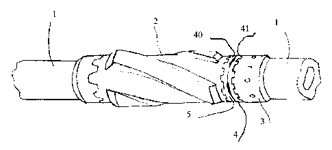
The figure 1 represents a logging while drilling collar 1 to which a
stabilizer 2 is
fixed by a nut 3. The stabilizer 2 is slid onto the collar until it encounters
a castellated, or
similarly profiled, geometry, which prevents further axial or rotational
motion. The nut is
itself threaded to the collar. Connection between the stabilizer and the nut
is achieved
with a locking mechanism 4 according to the invention. The locking mechanism 4
comprises two disposable washers 40 and 41, each have one face designed to
engage the
stabilizer to be fixed and the corresponding nut 3. The washer 40 is thus
linked to the
stabilizer and cannot be disengaged from said stabilizer after the threaded
nut has been
tightened. This linking with the stabilizer on one side and the nut on the
other side may
be achieved by castellation, pins, lugs or similar means. The second, mutually
contacting
faces of washers 40 and 41 have two functions. The first one is to support the
thrust load
between the stabilizer and the nut while the threaded connection is tightened
and the
second one is to provide a convenient profile for welding said two washers
together. A
weld 5 thus links said two washers 40 and 41.
Figure 2 represent as second embodiment of the locking mechanism of the
invention wherein a threaded nut 3 is secured to the tool body 1 itself. A
known example
of application for such embodiment would be a screw on wear-band.
Before unscrewing the parts, the weld must be ground, or otherwise removed,
and
a circumferential undercut in the part below the weld allows grinding without
risk of
damaging the stabilizer or the nut. After disassembly the washers are
discarded, while
the other parts are undamaged and may be reused as often as necessary.
The locking mechanism of the invention can thus be easily used on any parts of
tool that are screwed one to another and, particularly when they rotate, and
also have to
support heavy loads or shocks.

Dessin représentatif
Une figure unique qui représente un dessin illustrant l'invention.
États administratifs

2024-08-01 : Dans le cadre de la transition vers les Brevets de nouvelle génération (BNG), la base de données sur les brevets canadiens (BDBC) contient désormais un Historique d'événement plus détaillé, qui reproduit le Journal des événements de notre nouvelle solution interne.

Veuillez noter que les événements débutant par « Inactive : » se réfèrent à des événements qui ne sont plus utilisés dans notre nouvelle solution interne.

Pour une meilleure compréhension de l'état de la demande ou brevet qui figure sur cette page, la rubrique Mise en garde , et les descriptions de Brevet , Historique d'événement , Taxes périodiques et Historique des paiements devraient être consultées.

Historique d'événement

Description Date
Réputée abandonnée - omission de répondre à un avis sur les taxes pour le maintien en état 2010-12-17
Demande non rétablie avant l'échéance 2010-12-17
Inactive : Morte - RE jamais faite 2010-12-17
Inactive : Abandon.-RE+surtaxe impayées-Corr envoyée 2009-12-17
Inactive : CIB de MCD 2006-03-12
Demande publiée (accessible au public) 2005-06-22
Inactive : Page couverture publiée 2005-06-21
Inactive : CIB en 1re position 2005-03-04
Exigences de dépôt - jugé conforme 2005-01-28
Lettre envoyée 2005-01-28
Inactive : Certificat de dépôt - Sans RE (Anglais) 2005-01-28
Demande reçue - nationale ordinaire 2005-01-28
Inactive : Transfert individuel 2005-01-20
Modification reçue - modification volontaire 2005-01-20

Historique d'abandonnement

Date d'abandonnement Raison Date de rétablissement
2010-12-17

Taxes périodiques

Le dernier paiement a été reçu le 2009-11-19

Avis : Si le paiement en totalité n'a pas été reçu au plus tard à la date indiquée, une taxe supplémentaire peut être imposée, soit une des taxes suivantes :

  • taxe de rétablissement ;
  • taxe pour paiement en souffrance ; ou
  • taxe additionnelle pour le renversement d'une péremption réputée.

Veuillez vous référer à la page web des taxes sur les brevets de l'OPIC pour voir tous les montants actuels des taxes.

Historique des taxes

Type de taxes Anniversaire Échéance Date payée
Taxe pour le dépôt - générale 2004-12-17
Enregistrement d'un document 2004-12-17
TM (demande, 2e anniv.) - générale 02 2006-12-18 2006-11-09
TM (demande, 3e anniv.) - générale 03 2007-12-17 2007-11-08
TM (demande, 4e anniv.) - générale 04 2008-12-17 2008-11-05
TM (demande, 5e anniv.) - générale 05 2009-12-17 2009-11-19
Titulaires au dossier

Les titulaires actuels et antérieures au dossier sont affichés en ordre alphabétique.

Titulaires actuels au dossier
SCHLUMBERGER CANADA LIMITED
Titulaires antérieures au dossier
PETER AIREY
Les propriétaires antérieurs qui ne figurent pas dans la liste des « Propriétaires au dossier » apparaîtront dans d'autres documents au dossier.
Documents

Pour visionner les fichiers sélectionnés, entrer le code reCAPTCHA :


Pour visualiser une image, cliquer sur un lien dans la colonne description du document. Pour télécharger l'image (les images), cliquer l'une ou plusieurs cases à cocher dans la première colonne et ensuite cliquer sur le bouton "Télécharger sélection en format PDF (archive Zip)" ou le bouton "Télécharger sélection (en un fichier PDF fusionné)".

Liste des documents de brevet publiés et non publiés sur la BDBC .

Si vous avez des difficultés à accéder au contenu, veuillez communiquer avec le Centre de services à la clientèle au 1-866-997-1936, ou envoyer un courriel au Centre de service à la clientèle de l'OPIC.


Description du
Document 
Date
(aaaa-mm-jj) 
Nombre de pages   Taille de l'image (Ko) 
Dessins 2004-12-17 1 28
Revendications 2004-12-17 1 20
Description 2004-12-17 3 143
Abrégé 2004-12-17 1 12
Dessin représentatif 2005-05-25 1 15
Page couverture 2005-06-08 1 40
Courtoisie - Certificat d'enregistrement (document(s) connexe(s)) 2005-01-28 1 105
Certificat de dépôt (anglais) 2005-01-28 1 158
Rappel de taxe de maintien due 2006-08-21 1 110
Rappel - requête d'examen 2009-08-18 1 125
Courtoisie - Lettre d'abandon (requête d'examen) 2010-03-25 1 165
Courtoisie - Lettre d'abandon (taxe de maintien en état) 2011-02-11 1 173
Correspondance de la poursuite 2005-01-20 1 36