Sélection de la langue

Search

Sommaire du brevet 2490595 

Énoncé de désistement de responsabilité concernant l'information provenant de tiers

Une partie des informations de ce site Web a été fournie par des sources externes. Le gouvernement du Canada n'assume aucune responsabilité concernant la précision, l'actualité ou la fiabilité des informations fournies par les sources externes. Les utilisateurs qui désirent employer cette information devraient consulter directement la source des informations. Le contenu fourni par les sources externes n'est pas assujetti aux exigences sur les langues officielles, la protection des renseignements personnels et l'accessibilité.

Disponibilité de l'Abrégé et des Revendications

L'apparition de différences dans le texte et l'image des Revendications et de l'Abrégé dépend du moment auquel le document est publié. Les textes des Revendications et de l'Abrégé sont affichés :

  • lorsque la demande peut être examinée par le public;
  • lorsque le brevet est émis (délivrance).
(12) Brevet: (11) CA 2490595
(54) Titre français: METHODE ET APPAREIL DE SUSPENSION D'EXTENSIONS ARTICULEES CENTRALEMENT
(54) Titre anglais: CENTER PIVOT WING FLOTATION METHOD AND APPARATUS
Statut: Accordé et délivré
Données bibliographiques
(51) Classification internationale des brevets (CIB):
  • A01C 7/08 (2006.01)
  • A01B 63/10 (2006.01)
  • A01C 5/00 (2006.01)
(72) Inventeurs :
  • GUST, JACOB N. (Etats-Unis d'Amérique)
  • WAKE, WILLIAM A. (Etats-Unis d'Amérique)
(73) Titulaires :
  • CNH AMERICA LLC
(71) Demandeurs :
  • CNH AMERICA LLC (Etats-Unis d'Amérique)
(74) Agent: GOWLING WLG (CANADA) LLP
(74) Co-agent:
(45) Délivré: 2010-10-19
(22) Date de dépôt: 2004-12-20
(41) Mise à la disponibilité du public: 2005-09-27
Requête d'examen: 2007-01-17
Licence disponible: S.O.
Cédé au domaine public: S.O.
(25) Langue des documents déposés: Anglais

Traité de coopération en matière de brevets (PCT): Non

(30) Données de priorité de la demande:
Numéro de la demande Pays / territoire Date
10/810,455 (Etats-Unis d'Amérique) 2004-03-27

Abrégés

Abrégé français

Il s'agit d'une méthode et d'un appareil permettant de suspendre les extensions repliables d'une semeuse à un point central du bâti principal de façon à permettre aux extensions individuelles de pivoter au centre de l'axe longitudinal afin de mieux épouser le profil du terrain.


Abrégé anglais

A method and apparatus for proving a flotation for the wings of a foldable wing of an agricultural seeder that are centrally suspended from the main frame such that individual wings are pivotable centrally of the longitudinal axis therefore to better follow the contours of the ground.

Revendications

Note : Les revendications sont présentées dans la langue officielle dans laquelle elles ont été soumises.


Claims:
1. A method for providing flotation to a wing of an agricultural seeder
relative to the
ground, comprising the steps of:
a) providing a wheel-supported main frame adapted to be removably affixed to a
tractor for movement along the ground in a direction of travel;
b) providing a first elongated wing with an inner end and an opposing outer
end, the
first wing having a longitudinal axis generally perpendicular to the direction
of travel and
a center point along the longitudinal axis generally equidistant from the
inner and outer
ends;
c) providing a first plurality of agricultural implements affixed to the first
wing and
generally regularly spaced along the longitudinal axis thereof;
d) providing a first elongated support arm pivotally affixed at one end to the
main
frame and at the other end to the center point of the first wing;
e) providing a first hydraulic cylinder interconnecting directly at the first
support
arm and directly at the main frame such that the first cylinder can raise the
first wing to a
transport position and lower the first wing to a working position in contact
with the
ground;
f) providing a second elongated wing with an inner end and an opposing outer
end,
the second wing having a longitudinal axis generally perpendicular to the
direction of
travel and a center point along the longitudinal axis generally equidistant
from the inner
and outer ends, said inner ends of said respective first and second wings
being generally
adjacent to each other in the working position and form a generally continuous
line across
the width of the seeder;
g) providing a second plurality of agricultural implements affixed to the
second wing
and generally regularly spaced along the longitudinal axis thereof-
6

h) providing a second elongated support arm pivotally affixed at one end to
the main
frame opposite the point at which the first support arm is affixed and at the
other end to
the center point of the second wing such that the first and second wings are
on opposite
side of the main frame:
i) providing a second hydraulic cylinder interconnecting directly at the
second
support arm and directly at the main frame such that the second cylinder can
raise the
second wing to a transport Position and lower the second wing to a working
position in
contact with the ground;
j) lowering the first and second wings to the ground by activating the
respective first
and second hydraulic cylinders; and
k) locking the first and second hydraulic cylinders in the lower position
whereby the
first and second wings float about the point at which the first and second
support arms are
pivotally affixed to the center points of the respective first and second
wings,
wherein the first and second wings are only attached to the wheel-supported
main frame
by the first and second support arms, respectively, so that inner and outer
ends pivot freely only
about the center point of each first and second wings.
2. The method of claim 1, including the step of:
activating the first and second hydraulic cylinders at the same time to raise
and lower the
first and second wings in substantial unison.
3. An agricultural seeder comprising:
a wheel-supported main frame with first and second opposing lateral sides and
adapted to
be removably affixed to a tractor for movement along the ground in a direction
of travel;
first and second elongated wings each with an inner end and an opposing outer
end and
each having a longitudinal axis generally perpendicular to the direction of
travel and a center
point along the longitudinal axis generally equidistant from the respective
inner and outer ends;
7

a plurality of agricultural implements affixed to the first and second wings
and generally
regularly spaced along the longitudinal axes thereof;
a first elongated support arm pivotally affixed at one end to the first
lateral side of the
main frame and at the other end to the center point of the first wing;
a second elongated support arm pivotally affixed at one end to the second
lateral side of
the main frame and at the other end to the center point of the second wing;
a first hydraulic cylinder interconnecting the first elongated support arm and
the main
frame such that activation of the first cylinder can raise the first wing to a
transport position and
lower the first wing to a working position in contact with the ground;
a second hydraulic cylinder interconnecting the second elongated support arm
and the
main frame such that activation of the second cylinder can raise the second
wing to a transport
position and lower the second wing to a working position in contact with the
ground, whereby
lowering and locking;
the respective inner ends of said wings being closely adjacent to each other
when in the
working position, forming a generally continuous line across the width of said
seeder; and
both the first and second hydraulic cylinders having a lock position to hold
the
corresponding wings in the working position whereby when in the working
position, the wings
float relative to the ground, wherein the first and second wings are only
attached to the wheel-
supported main frame by the first and second support arms, respectively, so
that inner and outer
ends float only about the center point of each first and second wings.
4. The seeder of claim 3, further including:
a hydraulic control system connected to the first and second hydraulic
cylinders to
manage the activation of the cylinders.
5. In an agricultural seeder having a main frame with first and second
opposing lateral sides
and first and second wings pivotably attached thereto and a hydraulic control
system that pivots
8

the wings between a raised transport position and a lowered operating position
in contact with
the ground, the improvement comprising:
the first and second wings, each with a longitudinal axis and a center point
along their
respective longitudinal axes, the first and second wings only pivotably
attached to respective
lateral sides of the main frame by a structure including first and second
substantially identical
support arms each having a first end pivotably attached to the main frame and
an opposing
second end pivotably attached to the respective wing at the center point such
that the wings float
only about the centre point pivotally attached directly at the second end of
the support arm
relative to the ground;
each wing having and inner end and an outer end such that in the working
position the
respective longitudinal axes of the two are generally aligned, with the inner
ends closely adjacent
to each other thereby forming a generally continuous line along the width of
the seeder;
the hydraulic control system includes a first hydraulic cylinder
interconnecting the first
support arm and the main frame such that activation of the first cylinder can
raise the first wing
to transport position and lower the first wing to a working position in
contact with the ground;
and
the hydraulic control system includes a second hydraulic cylinder
interconnecting the
second support arm and the main frame such that activation of the second
cylinder can raise the
second wing to a transport position and lower the second wing to a working
position in contact
with the ground.
6. The improvement of claim 5, further including:
a plurality of agricultural implements affixed to the first and second wings
and generally
regularly spaced along the longitudinal axes thereof.
7. The improvement of claim 5, wherein:
both the first and second hydraulic cylinders have a lock position to hold the
corresponding wings in the working position whereby when in the working
position, the wings
float relative to the ground.
9

8. The method of claim 1, further including the step of:
moving the first and second elongated wings to the transport position wherein
both the
first and second elongated wings are generally vertically aligned.
9. The agricultural seeder as recited in claim 3, wherein the first and second
wings in the
transport position are generally vertically aligned.
10. The improvement of claim 5, wherein the first and second wing in the
transport position
are generally vertically aligned.

Description

Note : Les descriptions sont présentées dans la langue officielle dans laquelle elles ont été soumises.

CA 02490595 2004-12-20
M._
Docket No. 13911
CENTER PIVOT WING FLOTATION METHOD AND
APPARATUS
BACKGROUND OF THE INVENTION
I o 0 0l1 The present invention relates generally to a method and apparatus
for
providing flotation to a wing of a multi-piece toolbar of an agricultural
implement, and
more particularly to such method and apparatus that employs a center pivot
arrangement on the wing of an agricultural seeder.
L0o021 It is well known that various agricultural implements, such as tillage
equipment, seeders, and crop harvesting equipment are constructed in large
part of
multiple sections arranged end to end transversely to the direction of travel
of the
implement to provide a relatively wide operational path. Of course, in
general, the wider
the operational path, the more efficient and cost effective the process, and
in farming as
in any other business, time is money.
Ioo031 Most often the implement includes a main structural frame centrally
mounted on its own wheel structure, and the other sections, which include
toolbars and
structural members, that are usually disposed at both ends of the central main
frame.
These other sections are in the form of wings that may be folded upward to
make the
overall width less and thereby place the implement in transport position. When
the wing
sections are in their lowered work position, they are usually carried on their
own wheels
or other supporting mechanisms.
I0o047 In some known implements, the pivot connection which is provided
between the frame of the wing and the central main frame is arranged so that a
rigid
connection is formed between the main frame and the wing frames when the wings
are

CA 02490595 2004-12-20
lowered to their operative positions, but such a structure has the
disadvantage of
causing the ground working parts of the implement to vary their relation to
the ground
surface as the implement passes over uneven terrain. An arrangement such as
this
decreases in efficiency as the width of the implement or the unevenness of the
ground
increases. To overcome these problems, there have been designed pivoting
connections between the main frame and the frames of the wings which allow the
wings
to pivot relative to the main frame. These designs, too, do not provide a
completely
satisfactory solution to the problems, i.e., they do not accommodate ground
unevenness
well, because the wings only pivot about an axis located at their inner ends.
tooo5l There have been other attempts at improving the flotation of implement
wings, some better than others, but improved flotation has generally only
resulted from
designs that are complex, and expensive, and difficult to operate.
t o 0 o s 1 It would be advantageous to have a method and apparatus that
provide
flotation for the wings of an agricultural seeder that overcomes or
significantly reduces
the disadvantages of prior such systems, as described above.
SUMMARY OF THE INVENTION
tooo7~ It is an object of the instant invention to provide an improved
flotation
system for the wings of a ground engaging agricultural implement.
to0087 It is another object of the instant invention to provide an improved
flotation
method and structural arrangement for the wings of an agricultural seeder.
t o 0 0 9 ~ It is yet another object of the instant invention to provide an
improved
flotation system for the wings of an agricultural seeder that centrally pivots
each wing
from the main frame of the implement.
2

CA 02490595 2004-12-20
y.._
o o to ) It is an even still further object of the instant invention to
provide a flotation
system for the wings of an agricultural seeder that is durable in
construction,
inexpensive to manufacture, carefree of maintenance, facile in assemblage, and
simple
and effective in use.
tools) These and other objects and features are obtained by providing a
flotation
method and apparatus for a the wings of an agricultural seeder that are
centrally
suspended from the main frame such that individual wings are pivotable
centrally of the
longitudinal axis therefore to better follow the contours of the ground.
BRIEF DESCRIPTION OF THE DRAWINGS
Loo~2) The advantages of this invention wiH become apparent upon consideration
of the following detailed disclosure of the invention, especially when taken
in
conjunction with the accompanying drawings wherein:
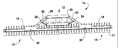
I o 013 ) Fig. 1 is a rear plan view of an agricultural implement showing a
central
main frame with wings depending from either end thereof, sitting on level
ground; and
t o 014 ) Fig. 2 is a rear plan view, similar to Fig. 1, showing flotation of
the wings
when the implement sits on uneven ground.
DETAILED DESCRIPTION OF THE PREFERRED EMBODIMENT
t o 01s ) Many of the fastening, connection, processes and other means and
components utilized in this invention are widely known and used in the field
of the
invention described, and their exact nature or type is not necessary for an
understanding and use of the invention by a person skilled in the art, and
they will not
therefore be discussed in significant detail. Also, any reference herein to
the terms "left"
and "right", or "up° and "down" are used as a matter of mere
convenience, and are
3

CA 02490595 2004-12-20
,.
determined by standing at the rear of the mechanism facing in its normal
direction of
travel. Furthermore, the various components shown or described herein for any
specific
application of this invention can be varied or altered as anticipated by this
invention and
the practice of a specific application of any element may already by widely
known or
used in the art by persons skilled in the art and each will likewise not
therefore be
discussed in significant detail.
I o o i 6 7 Fig. 1 depicts a rear elevational view of a seeder 10 as it sits
or moves
forward along generally level ground, G1. The structure of a seeder is
generally well-
known in the agricultural industry, and, since no specific model or
arrangement of most
seeder elements is important to the present invention, only those parts
necessary to
impart a clear understanding of the invention are shown. For a more complete
description and depiction of the various components of an exemplary seeder,
attention
is directed to U.S. Patent No. 6,125,775.
I o o ~~ 1 Referring again to Fig. 1, the seeder 10 is shown to comprise a
central
main frame 12 that would be removably connected to a tractor for forward
movement
and as a source of hydraulic power. Main frame 12, and the majority of the
constructional elements of seeder 10, are constructed primarily of steel box
beams or
pipes of various inside dimensions. Seeder 10 is supported above the ground,
and
when in the transport mode, by multiple wheels (not shown) generally
symmetrically
located at positions appropriate for safely and function. Two independent
toolbars or
wings, generally shown as 14 and 16, provide complete support for the seed-
planting
units (not shown), discs 18 and other necessary operational elements. Discs 18
and
some other components of the seeding mechanism are usually supported on
multiple
structural members spaced horizontally from each other, though interconnected.
While
two wings are shown in the drawings, it is possible to support additional
laterally
extending wings in a manner similar to that to be described below.
4

CA 02490595 2004-12-20
f r.
o o X81 Wings 14, 16 are totally supported from main frame 12 by a pair of
support
arms 22, 24, respectively. Support arms 22, 24, are pivotally connected at one
end to
the upper portion of main frame 12, respectively, by pivot pins 28, 30. The
location of
pivot pins 28, 30, is not necessarily high on main frame 12, though such a
location
permits a simplified construction. The other ends of support arms 22, 24, are
pivotally
affixed to respective wings 14, 16, by pivot pins 32, 34. Pins 32, 34 are
located
generally centrally along the length of the respective wings. By raising
(hydraulically)
the wheels (not shown) the distance between the ground, G1, and the wings 14,
16 may
be increased sufficiently to permit the wings to be pivoted, or folded, into a
transport
position where they are generally at least vertically directed. Hydraulic
cylinders 40, 42,
which can be located in a number of positions and arrangements, raise and
lower the
wings.
L 0 0191 Referring now to Fig. 2, the flotation provided by the system of the
instant
invention to the toolbars 14, 16 can be observed on uneven ground, G2. With
the
hydraulic cylinders 40, 42 locked in the lowered position, the wings are
allowed to pivot
about the centrally located pins 32, 34, and closely follow the contours of
the ground
G2. A good flotation system in a seeder assures more even plantings, with more
uniform depth and germination-all important characteristics of good crop
production.
too2o) It will be understood that changes in the details, materials, steps and
arrangements of parts which have been described and illustrated to explain the
nature
of the invention will occur to and may be made by those skilled in the art
upon a reading
of this disclosure within the principles and scope of the invention. The
foregoing
description illustrates the preferred embodiment of the invention; however,
concepts, as
based upon the description, may be employed in other embodiments without
departing
from the scope of the inventions. Accordingly, the following claims are
intended to
protect the invention broadly as well as in the specific form shown.

Dessin représentatif
Une figure unique qui représente un dessin illustrant l'invention.
États administratifs

2024-08-01 : Dans le cadre de la transition vers les Brevets de nouvelle génération (BNG), la base de données sur les brevets canadiens (BDBC) contient désormais un Historique d'événement plus détaillé, qui reproduit le Journal des événements de notre nouvelle solution interne.

Veuillez noter que les événements débutant par « Inactive : » se réfèrent à des événements qui ne sont plus utilisés dans notre nouvelle solution interne.

Pour une meilleure compréhension de l'état de la demande ou brevet qui figure sur cette page, la rubrique Mise en garde , et les descriptions de Brevet , Historique d'événement , Taxes périodiques et Historique des paiements devraient être consultées.

Historique d'événement

Description Date
Représentant commun nommé 2019-10-30
Requête pour le changement d'adresse ou de mode de correspondance reçue 2018-01-10
Accordé par délivrance 2010-10-19
Inactive : Page couverture publiée 2010-10-18
Inactive : Taxe finale reçue 2010-08-10
Préoctroi 2010-08-10
Un avis d'acceptation est envoyé 2010-03-08
Lettre envoyée 2010-03-08
Un avis d'acceptation est envoyé 2010-03-08
Inactive : Approuvée aux fins d'acceptation (AFA) 2010-03-03
Modification reçue - modification volontaire 2009-09-03
Inactive : Dem. de l'examinateur par.30(2) Règles 2009-03-06
Modification reçue - modification volontaire 2007-05-02
Lettre envoyée 2007-02-14
Requête d'examen reçue 2007-01-17
Exigences pour une requête d'examen - jugée conforme 2007-01-17
Toutes les exigences pour l'examen - jugée conforme 2007-01-17
Inactive : CIB de MCD 2006-03-12
Demande publiée (accessible au public) 2005-09-27
Inactive : Page couverture publiée 2005-09-26
Lettre envoyée 2005-03-22
Inactive : CIB en 1re position 2005-03-03
Inactive : Transfert individuel 2005-03-03
Inactive : CIB attribuée 2005-03-03
Inactive : Certificat de dépôt - Sans RE (Anglais) 2005-02-02
Exigences de dépôt - jugé conforme 2005-02-02
Demande reçue - nationale ordinaire 2005-01-29

Historique d'abandonnement

Il n'y a pas d'historique d'abandonnement

Taxes périodiques

Le dernier paiement a été reçu le 2009-12-04

Avis : Si le paiement en totalité n'a pas été reçu au plus tard à la date indiquée, une taxe supplémentaire peut être imposée, soit une des taxes suivantes :

  • taxe de rétablissement ;
  • taxe pour paiement en souffrance ; ou
  • taxe additionnelle pour le renversement d'une péremption réputée.

Veuillez vous référer à la page web des taxes sur les brevets de l'OPIC pour voir tous les montants actuels des taxes.

Titulaires au dossier

Les titulaires actuels et antérieures au dossier sont affichés en ordre alphabétique.

Titulaires actuels au dossier
CNH AMERICA LLC
Titulaires antérieures au dossier
JACOB N. GUST
WILLIAM A. WAKE
Les propriétaires antérieurs qui ne figurent pas dans la liste des « Propriétaires au dossier » apparaîtront dans d'autres documents au dossier.
Documents

Pour visionner les fichiers sélectionnés, entrer le code reCAPTCHA :


Pour visualiser une image, cliquer sur un lien dans la colonne description du document. Pour télécharger l'image (les images), cliquer l'une ou plusieurs cases à cocher dans la première colonne et ensuite cliquer sur le bouton "Télécharger sélection en format PDF (archive Zip)" ou le bouton "Télécharger sélection (en un fichier PDF fusionné)".

Liste des documents de brevet publiés et non publiés sur la BDBC .

Si vous avez des difficultés à accéder au contenu, veuillez communiquer avec le Centre de services à la clientèle au 1-866-997-1936, ou envoyer un courriel au Centre de service à la clientèle de l'OPIC.


Description du
Document 
Date
(aaaa-mm-jj) 
Nombre de pages   Taille de l'image (Ko) 
Abrégé 2004-12-20 1 11
Description 2004-12-20 5 243
Revendications 2004-12-20 4 175
Dessins 2004-12-20 2 39
Dessin représentatif 2005-09-01 1 8
Page couverture 2005-09-19 1 32
Revendications 2009-09-03 5 192
Dessins 2009-09-03 2 37
Dessin représentatif 2010-09-29 1 10
Page couverture 2010-09-29 1 34
Certificat de dépôt (anglais) 2005-02-02 1 158
Courtoisie - Certificat d'enregistrement (document(s) connexe(s)) 2005-03-22 1 105
Rappel de taxe de maintien due 2006-08-22 1 110
Accusé de réception de la requête d'examen 2007-02-14 1 176
Avis du commissaire - Demande jugée acceptable 2010-03-08 1 165
Correspondance 2005-02-03 1 23
Taxes 2006-10-13 1 39
Taxes 2007-12-13 1 40
Taxes 2008-12-05 1 41
Taxes 2009-12-04 1 39
Correspondance 2010-08-10 2 57