Note : Les descriptions sont présentées dans la langue officielle dans laquelle elles ont été soumises.
CA 02490612 2004-12-20
Docket No. 15244
COLLAPSIBLE G N=CHU__TE
BACKGROUND OF THE INVENTION
[00011 In general terms, the instant invention relates to an agricultural
seed planter, and more particularly to a grain chute for attachment the bulk
seed
assembly distributor of a seed planter to improve the deanout process when
either changing the variety of seed being planted or prior to seasonal storage
of
the unit
[00021 By and large, modem agricultural seed planters employ a plurality
row dispensing bins, each of which has an associated metering device for
applying preselected quantities of the seed to the land. These individual bins
generally have limited storage capacity, for example one to three bushels, and
therefore require frequent refilling. To avoid the lost time and excess fuel
usage
associated with frequent refilling, apparatus was developed using a central
bulk
supply of seed carried by the frame of the planter so that the dispensing bins
can be resupplied with seed during operation in the freid. A seed distribution
system in which grain is conveyed from a main hopper can be seen in U.S.
Patent No. 5,161,473. This system utilizes a single main hopper which
dispenses seed to a plurality of individual or mini-hoppers that each, in
turn,
supply seed to an individual row planting mechanism. The seed is fed from the
main hopper into each mini-hopper by entraining it In an air stream contained
in
separate, individual transfer hoses that are connected between the main tank
and each of the Individual mini-hoppers.
[00031 U.S. Patent No. 5,379,706 illustrates another seed planting system
that also utilizes a central storage hopper for supplying a plurality of
smaller,
1
CA 02490612 2004-12-20
satellite hoppers via a plurality of individual hoses or tubes running from
the
central hopper to each of the individual satellite, row hoppers. Thus, while
the
systems of the '473 and '706 patents provide for the maintenance of seed
supply
quantities in the row hoppers during seeding operations, U" also require the
incorporation of a large number of separate seed transport tubes In those
systems where multiple, mini-hoppers are present.
100041 The'473 and 706 patents are merely illustrative of the general
type of seeder relevant to the instant invention. There are many improvements
or alternative arrangements available today on the markett, but all "air
seeders"
generally work on the same or similar principles. A bulk storage bin,
supported
by the planter frame, feeds seed via gravity Into a manifold-like distributor,
located below the storage bin, where the seeds are air pushed into a
multiplicity
of outlets through individual hoses to the satellite hoppers. In some
instances,
more than one bulk storage bin, most often two, is used, each fading a
separate portion or section of the mini-hoppers.
(0005] Some difficulties and shortcomings have been identified in the field
operation of systems such as described above, particularly when the bulk
storage bins are to be emptied for end of the season storage or when making a
change in the type or variety of seed being planted. To completely empty the
bulk storage bin the operator must either remove the distributor or the bottom
enclosure cover thereof and catch the extra grain in a sack or sacks. This is
a
somewhat difficult task in that the sack may become full, requiring quick
replacement, or may have an inadequately small opening, allowing seed to misss
the sack and fall directly on the ground.
(00061 It would be quite advantageous to have a means for fully and
conveniently emptying the bulk bins of a seed planter without losing expensive
seed or creating an over planted area in the field.
2
CA 02490612 2004-12-20
SUMMARY OF THE INVENTION
[00071 Accordingly, it is an object of the instant invention to provide an
attachment to the bulk seed distributor of a seed planter that greatly
improves
the ability to effectively and efficiently empty the bulk seed bin.
[0008] it is another object of the instant invention to provide a grain chute
for the bulk seed distributor of a seed planter that ensures effective and
efficient
elimination of seed materials from the bulk seed bin.
[0009] It is a further object of the instant invention to provide a
collapsible
grain chute for the bulk seed distributor of an agricultural seed planter that
promotes the effective and efficient emptying of the bulk seed bin of the
planter.
[00101 It is a still further object of the instant invention to provide a
collapsible grain chute with a conical shape that affixes to the bulk seed
distributor of an agricultural seed planter to provide effective and efficient
emptying of the bulk seed bin of the planter.
[00111 It is an even 9011 further object of the Instant invention to provide a
collapsible grain chute, made of a flexible Both-like material, that affixes
to the
bulk seed distributor of an agricultural seed planter to provide effective and
efficient emptying, via gravity, of the bulk seed bin of the planter.
[00121 It is another objected of the Instant invention to provide a generally
conically-shaped collapsible grain chute, with a cinch cord to selectively
dose
the chute; the chute affixes to the bulk seed distributor of an agricultural
seed
planter to provide effective and efficient empting of the bulk seed bin of the
planter.
3
CA 02490612 2004-12-20
C l
100131 These and other objects are obtained by providing a generally
conically-shaped collapsible grain chute affixed to the bulk seed distributor
of an
agricultural planter to provide an effective and efficient apparatus for
emptying
the bulk seed bin. The chute may include a cinch cord to selectively open and
close the chute to control the flow of seed therethrough.
BRIEF DESCRIPTION OF THE DRAWINGS
E00141 The advantages of this invention will be apparent upon
consideration of the following detailed disclosure of the invention,
especially
when taken in conjunction with the accompanying drawings wherein:
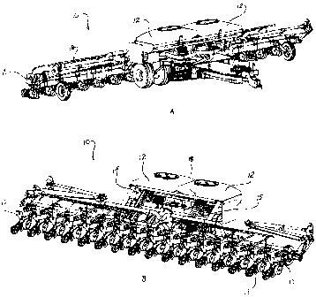
10015] FIG. 1A is a front perspective view of an agricultural planter of the
general type with which the Instant Invention may be used, showing, among
other things, a pair of bulk seed bins and a plurality of satellite hoppers
being
fed therefrom;
[00161 FIG. 1B is a rear perspective view of the planter of FIG. 1A;
[0017] FIG. 2 is a left end view of a bulk seed distributor with the
collapsible chute of the Instant invention;
100181 FIG. 3 is a rear perspective, partially exploded, view of a suitable
distributor in combination with the collapsible chute of the instant
invention; and
10019] FIG. 4 is a front perspective, partially exploded, view of the
distributor/chute combination of the FIG. 3.
4
CA 02490612 2004-12-20
DETAILED DESCRIPTION OF THE PREFERRED EMBODIMENT
[0020] Many of the fastening, connection, processes and other means and
components utilized in this invention are widely known and used in the field
of
the invention described, and their exact nature or type is not necessary for
an
understanding and use of the invention by a person skilled in the art, and
they
will not therefore be discussed in significant detail. Also, any reference
herein to
the terms left" or "right' are used as a matter of more convenience, and are
determined by standing at the rear of the machine facing in its normal
direction
of travel. Furthermore, the various components shown or described herein for
any specific application of this invention can be varied or altered as
anticipated
by this invention and the practice of a specific application of any element
may
already by widely known or used In the art by persons skilled in the art and
each
will likewise not therefore be discussed In significant detail.
[0021] FIGS. 1A and 18 show a pneumatic seed planting system (also
known as an 'air seeder") as it would be used in conjunction with the
invention
as described below. Reference numeral 10 indicates an agricultural planter
which may be connected to a prime mover, such as a tractor, for transport
through a field. The planter or seeder 10 is shown as having two bulk storage
bins 12 and a plurality of Individual distribution or row metering hoppers 13
that
receive seed from the storage bins 12 by means of a distribution system
indicated generally by the numeral 15. Generally speaking, storage bins 12
could have capacities ranging from 50 to about 340 bushels while the
individual
row hoppers would cha rcteristically range from about one quart to three
bushels in capacity. Each of the row metering bins 13 will have an associated
seed metering device that applies the seed to the soil in a manner well-known
in
the industry. Each seed transport hose 18 is connected to supply seed to
individual row hoppers. The ability of the system to supply seed to a
comparatively large member of row hoppers is facilitated by the design of a
CA 02490612 2009-09-08
single seed transport duct that is connected to a hopper 12 at one end and
which extends from there outwardly over a series of row bins. The delivery
system includes a source of air, such as blower, that is connected by air
supply
tubes to the bottom of storage bins 12. Air entering into the bin 12 picks up
seeds and pneumatically transports them through hoses 16 into the inlet ends
of
a manifold supply hose. The planter can be of substantially any conventional
design and configuration. FIGS. 1A and 1 B depict the Case 1200 Series
Advanced Seed Planter.
(00221 FIG. 2 is an end view of an exemplary bulk seed distributor 30
attached to bulk storage bin 12. The attachment location between these two
components will normally be at the lowest point of bin 12 relative to the
ground
so that seeds in bin 12 will be encouraged to flow into the distributor by the
force
of gravity. Referring also to FIGS. 3 and 4, the distributor 30 can be seen to
comprise, basically, a box like enclosure with a top opening 32 in flow
communication with storage bin 12 and an opposing bottom opening. During
operation of the planter, opening is normally dosed by a generally flat plate
(not shown) affixed In to the main generally rectangular body portion 36 of
distributor 30. However, when the planter is to be cleaned or emptied of seed,
the flat plate is removed and the collapsible chute 60 is attached to
generally
fully encompass opening 32.
(00231 Distributor 30 further includes an opening 38 in the forward wail for
the insertion of pressurized air to assist in movement of seeds through the
system. The wall opposite opening 38 is a manifold-like series of outlet
connectors 40 to which hoses 42 are connected for distribution to row metering
hoppers 13. Distributor 30 is affixed to bin 12 via flange 44 which mates with
a
matching flange 46 on bin 12 by bolts or other suitable mechanical mechanisms.
100241 Collapsible chute 60 is comprised of a main body 62 that is
6
CA 02490612 2004-12-20
generally shaped like a hollow truncated funnel terminating at the top end in
a
large inlet opening 64 generally the same shape and size of bottom opening 32
of distributor 30, and terminating at the bottom end in a smaller opening 66.
Opening 66 may include a hem 68 with a cinch chord 70 (FIG. 2) therein to
permit the opening 68 to be selectively closed. The main body 62 may be made
of any flexible material with sufficient durability to withstand the
conditions under
which it must operate. For example, main body 62 may be made of canvas,
nylon or other synthetic materials. As seen best in FIGS. 2-4, an elongated
plate 72 is affixed to one end of main body 62, as by rivets through holes 74
and
extends beyond the associated edge of main body 62. Plate 72 has a horizontal
top-opening slot 76 therein and a protruding catch 78. A retaining member 80,
affixed to main body 62 and protruding away therefrom is sized to allow slot
76
to slide over m end 80 and moved into position to hold plate 72 in the
operating location. An over-the-center latch 82 engages catch 78 to lock chute
60 into engagement with distributor 30. The opposing end of the chute 60 and
distributor 30 are duplicates of the corresponding ends just described, but
are
not shown. Other latches and/or slot arrangements can be used effectively so
long as one end of the chute can be generally fixed In position relative to
the
bottom opening 32 in distributor 30 and the opposing end pivoted and locked
into operating position. Also, a cinch chord or a friction fit could be used
to hold
the chute in position. The location below the distributor in which the chute
is
maintained in operation is usually quite confined, so the pivottlocking
arrangement is a significant practical feature. In some configurations, the
bottom opening 32 may be centered axially with the inlet opening 64 of main
body 62, i.e., it is axially symmetrical. In other situations, because of
interference with other components in the general area, the bottom opening is
offset, as shown in FIG. 2.
[0025] In operation, when it is necessary to empty the bulk storage bin 12,
the bottom plate of distributor 30 is removed and the collapsible chute 60 is
7
CA 02490612 2004-12-20
attached over the opening. The operator, by controlling the flow by opening
and
dosing opening 66, allows the remaining seeds to flow into sacks or bags for
later use or storage. When bin 12 is empty, the chute 60 is replaced by the
bottom plate, and then put away in a storage box on the planter or tractor.
Being
flexible and not having a full rigid frame around the top end, the chute may
be
collapsed into a relatively small flat package, making storage more convenient
and efficient.
100261 It will be understood that changes In the details, materials, steps
and arrangements of parts which have been described and illustrated to explain
the nature of the invention will occur to and may be made by those skilled in
the
art upon a reading of this disclosure within the principles and scope of the
invention. The foregoing description illustrates the preferred embodiment of
the
invention; however, concepts, as based upon the description, may be employed
in other embodiments without departing from the scope of the inventions.
Accordingly, the following claims are intended to protect the invention
broadly as
well as in the specific form shown.
8