Note : Les descriptions sont présentées dans la langue officielle dans laquelle elles ont été soumises.
CA 02491499 2005-O1-05
Docket No. 8006-2
CONTAINER
CROSS-REFERENCE TO RELATED APPLICATIONS
[0001] This application claims the benefit of U.S. Provisional Application No.
60/573,175, filed May 21, 2004, U.S. Provisional Application No. 601613,876,
filed
September 28, 2004, and U.S. Provisional Application No. 60/614,220, filed
September 29,
2004, of which the entirety of each application is hereby incorporated by
reference.
BACKGROUND
[0002] The present invention is a novel container that includes an applicator
shelf. The
container is practical for use with any fluids that might by applied by
roller, including, for
example, paints, stains, water repellants, adhesives, or sizing. The shelf
allows for
distribution of a fluid that could be contained in the base member onto an
applicator. The
shelf additionally provides for drainage of excess fluid from the applicator
and from the shelf
itself. The container also includes a lid, which is locked onto the base
member of the
container during initial transportation and storage of the container.
Additives, such as
colorants, catalysts, biocides, or other materials, could be added by removing
the lid, adding
the desired additive, and then resealing the lid, or they could be added into
the container
through a resealable additive hole, such as an additive hole that contains a
plug, that can be
incorporated into the topside of the lid. If a resealable additive hole is
incorporated into the
lid, it is not necessary to disengage the lid from the base member to
incorporate the additive.
Thus, the lid could remain locked onto the base member to prevent accidental
removal of the
lid. The lid is removable by the consumer such as by disengagement of a tear-
off strip. The
tear-off strip serves as one locking mechanism by which the lid is engaged
onto the base
member. Even after the tear-off strip is removed, a second locking mechanism
can serve to
engage the lid onto the base member so that any materials remaining in the
container can be
stored in the container until needed. The container also includes a handle,
such as a wire bail
or plastic handle, for easy transport. One useful application of the container
is for containing
coatings such as paints or stains.
[0003] Because the shelf of the present invention is contained entirely within
the base
member, one problem that is typically encountered with conventional roller
trays is resolved;
namely, an instance where paint or other material must be poured from its
container into a
CA 02491499 2005-O1-05
Docket No. 8006-2
well of a conventional roller tray, thereby creating unwanted mess and waste.
The container
also reduces the mess and waste at the end of a job where paint or other
material remains in
the well of the conventional roller tray. Since the base member of the present
invention itself
contains the paint or other material and a shelf to be used for a particular
project, it is also
unnecessary for a consumer to purchase a separate roller tray.
SUMMARY OF THE INVENTION
(0004] The present invention is directed to a container. One object of the
present
invention is to provide a container to store, provide access to, and dispense
liquids. In one
embodiment, the container includes a base member, and the base member further
includes a
well that comprises a floor and a back wall, a first sidewall, a front wall
and a second
sidewall. 'The container of this embodiment includes a lid and also includes a
shelf that is
housed within the base member.
[0005] The shelf of this embodiment includes a top surface, and an underside
also
includes and at least one hole through the shelf. In an alternative
embodiment, the shelf can
be constructed with a continuous surface without any holes therethrough. The
shelf is
adapted to receive an applicator, such as a paint roller. The shelf may
include at least one
hole, and alternatively a plurality of holes, to provide for drainage of
excess fluid from the
application. In this embodiment, the shelf may also include one or more ribs
to assist in the
dispersion of the fluid onto the applicator.
[0006] The shelf of this embodiment includes a novel integrated pouring spout.
Through
use of the spout, the user may transfer fluid that is contained in the base
member into a
separate container cleanly and easily. In one embodiment the pouring spout is
an upward
projection including at least one sidewall. In an alternative embodiment, the
pouring spout is
an upward projection including at least two adjacent sidewalls.
[0007] In one embodiment, the lid includes an opening therethrough. The
opening can
include a removable plug that is affixed into the opening. The plug may, for
example, be
removed in order to introduce an additive to the fluid contained in the
container without
removing the lid, and is used to reseal the additive hole.
(0008] In an alternative embodiment, the container also includes a handle.
2
CA 02491499 2005-O1-05
Docket No. 8006-2
(0009] Another embodiment of this invention provides for a shelf that can be
used as an
applicator surface to assist in the distribution of a fluid onto an
applicator. One such
applicator that can be used in accordance with this embodiment is a paint
roller. The shelf is
positioned within a container to allow for drainage of excess fluid into the
container. In one
embodiment, the shelf includes an integrated pouring spout. The pouring spout
can be an
upward projection, and includes at least one sidewall.
[0010] Yet another embodiment of this invention provides for a process of
mixing an
additive into a fluid contained in a container. The process of this embodiment
includes
providing a container, where the container further includes a fluid and a
shelf suspended over
a portion of the fluid; providing a lid that is affixed onto the container,
where the lid includes
a lid opening that houses a resealable plug; adding an additive to the
container through the lid
opening; and affixing the plug into the lid opening. The process of this
embodiment also
includes agitating the container.
[0011] Another embodiment of this invention provides for a process of mixing a
colorant
in a container. The process of this embodiment includes providing a container;
providing a
lid that is affixed onto the container, where the lid includes a lid opening
that houses a
resealable plug; adding colorant to the container through the lid opening; and
affixing the
plug into the lid opening. The container further includes paint and a paint
roller shelf that is
suspended over at least a portion of the paint. The process of this embodiment
also includes
agitating the container.
[0012] Yet another embodiment of the present invention provides for a process
of
applying paint to a roller. The process of this embodiment includes providing
a container
with an opening into a fluid storage area; and providing a shelf suspended
over the fluid
storage area. The shelf of this embodiment includes an integrated pouring
spout.
(0013) Another embodiment of this invention provides for an adapter to be used
during
agitation of the container. The adapter is placed on the surface of a lid of a
container and
bears the force of a pressure plate of a mixer. The adapter is designed to
receive downward
force from the pressure plate and apply that force evenly and uniformly on the
container lid to
keep the lid in place during agitation.
3
CA 02491499 2005-O1-05
Docket No. 8006-2
BRIEF DESCRIPTION OF THE DRAWINGS
[0014] It will be appreciated that the illustrated boundaries of elements
(e.g., boxes or
groups of boxes) in the figures represent one example of the boundaries. One
of ordinary
skill in the art will appreciate that one element may be designed as multiple
elements or that
multiple elements may be designed as one element.
[0015] Further, in the accompanying drawings and description that follow, like
parts are
indicated throughout the drawings and description with the same reference
numerals,
respectively. The figures are not drawn to scale and the proportions of
certain parts may have
been exaggerated for convenience of illustration.
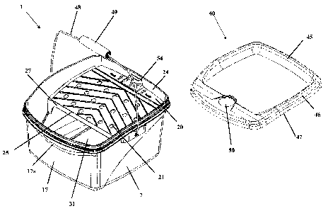
[0016] Fig. 1 is an exploded view of a container as described herein, said
container
including a base member with a shelf contained therein and a lid.
(0017] Fig. 2 is a side view of a container as described herein.
[0018] Fig. 3 is a perspective view of the container, specifically the back
and side of the
container.
[0019] Fig. 3a illustrates the lid tab and tear-off strip, with the tear-off
attached to the lid.
(0020] Fig. 4 is a perspective view of the base member with the lid, shelf,
and wire
handle removed.
[0021] Fig. 4a is a perspective view of a bail hole and bail groove into which
a handle can
be inserted.
[0022) Fig. 5 is a perspective view of the base member with the lid, shelf,
and wire
handle removed.
[0023] Fig. 6 is a cross-sectional view of the container, fully assembled as
herein
representatively described.
[0024] Fig. 6a is a cross-sectional view of the lid as engaged onto the base
member,
proximal to the lid tab.
4
CA 02491499 2005-O1-05
Docket No. 8006-2
[0025] Fig. 6b is a cross-sectional view of the lid as engaged onto the base
member,
proximal to a lower ring.
[0026] Fig. 7 is a perspective view of a shelf.
[0027] Fig. 8 is a perspective view of a shelf.
[0028] Fig. 9 is a perspective view of the bottom of a shelf.
[0029] Fig. 10 is a perspective view of the bottom view of a shelf.
[0030] Fig. 11 is a side view of a shelf.
[0031] Fig. 12 is a perspective view of the underside of a lid.
[0032] Fig. 13 is a perspective view of the underside of a lid.
[0033] Fig. 14 is a perspective view of the underside of a lid.
[0034] Fig. 15 is a perspective view of a fully assembled container as
described herein.
[0035] Fig. 15a is a perspective view of a bail handle as inserted into the
bail hole and
engaged with the bail groove.
[0036] Fig. 16 is a bottom view of the insert.
[0037] Fig. 17 is a top view of the insert.
[0038] Fig. 18 is a bottom view of the insert.
(0039] Fig. 19a is a bottom view of the insert.
(0040] Fig. 19b is a front view of the insert.
(0041] Fig. 19c is a side view of the insert.
[0042] Fig. 20 is a front view of the container housed in a shaker, with the
insert placed
on the lid of the container.
CA 02491499 2005-O1-05
Docket No. 8006-2
[0043] Fig. 21 is a front view of the container housed in a shaker, with the
insert placed
on the lid of the container.
(0044] Fig. 22 is a perspective view of the top of the insert.
(0045] Fig. 23 is a top view of the insert that is placed on container lid.
[0046] Fig. 24 is a front view of the container housed in a shaker, with the
insert placed
on the lid of the container.
[0047] Fig. 25 is a front view of the container housed in a shaker.
[0048] Fig. 26 is a perspective view of a shelf.
[0049] Fig. 27 is a perspective view of a shelf.
[0050] Fig. 28 is a perspective view of a shelf.
[0051] Fig. 29 is a perspective view of a shelf.
DETAILED DESCRIPTION OF ILLUSTRATED EMBODIMENTS
[0052] It should be noted that in the detailed description that follows,
identical
components have the same reference numerals, regardless of whether they are
shown in
different embodiments of the present invention. It should also be noted that
in order to
clearly and concisely disclose the present invention, the drawings may not
necessarily be to
scale and certain features of the invention may be shown in somewhat schematic
form.
[0053] Unless otherwise indicated, as used herein, the terms "about" and
"approximately"
mean ~ 10%.
[0054] As used herein the term "paint container" shall representatively
describe the
container as described. However, it should be appreciated that the container
can house any
variety of fluids, including but not limited to paints, stains, water
repellents, adhesives, or
sizing.
6
CA 02491499 2005-O1-05
Docket No. 8006-2
[0055] In one embodiment, this disclosure relates to an inclusive delivery
system that
provides a user with a fluid, a integrated shelf, and a lid in an easy-to-
transport, easy-to-use,
and easy-to-access container. In another useful embodiment, the delivery
system contains
paint and the shelf acts as a roller tray that provides for easy drainage and
removal of excess
paint into the reservoir of the container.
[0056] Referring first to Fig. 1, the container includes a base member
indicated generally
at 1, a shelf, or applicator surface, indicated generally at 20, and a lid
indicated generally at
40. The container also includes a fluid, and in one embodiment, includes
paint, that is housed
within the base member and sold with the container as an all-inclusive system.
Any quantity
of fluid may be included in accordance with the container as described herein.
The quantity
of fluid that may be placed in the container will be dictated by the size of
the base member,
and conversely, the size of the base member may be modified subject to the
quantity of fluid
desired to be contained therein. In one embodiment, the container will house
approximately
2.5 gallons of paint, The components of the container, namely the base member,
lid, and
shelf can each individually be made from any practical materials, including
plastics such as
polycarbonate, polypropylene, or polyethylene. The components of the
container, in one
useful embodiment, are constructed from high-density polyethylene (HDPE).
(0057] The base member acts as a reservoir from which paint is collected by a
roller, and
into which surplus paint drains through holes 21 in the shelf. The holes in
the shelf not only
provide for drainage of excess paint, but the holes also allow for ample color
dispersion after
colorant is introduced into the container and the container is placed into a
paint shaker. In
this way, the subject paint container can be sold with paint, which can later
be colored based
on user specifications. A lid is placed onto the base member and "locked" to
ensure that it
does not dislodge during shaking, and the lid is not required to be removed in
order to
introduce a colorant due to the presence of an additive hole through which a
colorant is
added. Thus, a paint container system is provided.
(0058] As best shown in Figs. 2, 3 and 4, the base member of the container of
the instant
invention comprises two side walls 7 spaced from each other, and a front wall
17 spaced from
a back wall 6, and a floor 3, and contains a predetermined quantity of fluid
therein. In one
embodiment, the upper portion of the front wall of the base member is
outwardly rounded to
form a lip 17a. A rounded lip provides more clearance for an applicator to be
inserted into
7
CA 02491499 2005-O1-05
Docket No. 8006-2
the base member to access the fluid composition. In an alternative embodiment,
the front
wall need not be rounded.
[0059) Though the base member can be of any shape, in one useful embodiment,
the base
member is generally non-cylindrical. Although shown herein as having a
generally
rectangular footprint, the container, e.g., base member and lid, may have
other shapes. For
example, the container could be any non-cylindrical shape. Likewise, the
container can be
any cylindrical shape, such as generally round or elliptical. In a case where
the container is a
cylindrical shape, the base member may have only one continuous, e.g.,
circumferential,
sidewall rather than the more than one sidewall as illustrated herein.
(0060) The base member can be tapered slightly from top to bottom, thereby
more easily
allowing nesting of multiple base members during storage and warehousing prior
to assembly
of the lid and shelf therein. Additionally, the tapering of the base member
provides a smaller
footprint for the container, allowing one filled and lidded container to be
stacked upon one
another, while being nested within the lid of the container beneath it, such
as in a store
display. In this manner, stacked containers are less likely to slide off or be
pushed off of one
another during storage.
(0061] In one embodiment, the bottom of the base member measures a width of
about
10.91 inches. The width of the top of the base member is about 12.75 inches,
from side wall
to side wall. A handle 48 is pivotally mounted to ears 13 that appear on the
sidewalk ?. In
this embodiment, the width of the base member as measured from one ear to the
opposing ear
is about 13.09 inches, and the length of the base member, from the front wall
to the back wall
is about 11.10 inches, as measured from the bottom of front wall to the bottom
of the back
wall. However, the length of the base member, as measured from the lip of the
base member
to the back wall of the base member is about 13.26 inches due to the outwardly
rounded lip of
this embodiment. A lid 40 (see Fig. 1) is also provided for engagement onto
the base
member. With the lid engaged onto the base member, the length of the base
member, as
measured from the front of the lid (proximal to the lip) the back of the lid
(proximal to the
back wall) is about 13.43 inches. In this embodiment, the height of the
container with the lid
engaged, as measured along the front wall from the bottom of the base member
to the top of
the lid, is about 6.69 inches. The height of the container with the lid
engaged, as measured
8
CA 02491499 2005-O1-05
Docket No. 8006-2
along the back wall from the bottom of the base member to the top of the lid,
is about 7.69
inches.
(0062) The central portion of the floor 3 of the base member is sloped
slightly downward
toward the front wall 17 of the base member. The slope of the central portion
of the floor is
greater than 90° but less than 180° relative to the x-axis. This
slope directs the paint or other
liquid toward the front of the base member where an access opening 31 is
provided (see Fig.
1 ). The side edges 4 of the floor remain flat and do not slope in order to
keep the container
stable and flat when placed on a surface during use, storage, or shaking in a
paint mixer.
[0063] In an alternative embodiment, the bottom surface of the side edges of
the floor
may include anti-skid ribs or grips, or other material that produces friction
between the
underside of the side edges and the surface upon which the container is
placed. In yet another
embodiment, the underside of the base member may, include casters or other
mechanisms
that allow the base member to be easily rolled, slid, or otherwise moved from
area to area.
Such a feature is particularly useful when the user wishes to transport the
container from one
area of a room or home without lifting the container while the container fully
or partially
contains a paint or other composition.
[0064] In one embodiment, the underside of the base member includes a recessed
finger
grip 5. As best shown in Figs. 3 and 6, the finger grip is located on the
underside of the base
member proximal to the front wall of the base member. The finger grip allows a
user easier
access and ability to move the container, such as for example, off of a store
shelf. The finger
grip may also be used to assist the user in tipping the base member in order
to pour paint out
of the base member through a pouring spout. The tipping finger grip allows the
user to pour
from the container without lifting the entire container off of the floor or
other surface upon
which the container is resting. It is desirable, therefore, that the finger
grip is located
opposite to a pouring spout or other region from which the fluid may be
poured.
Furthermore, a finger grip allows the user a means to stabilize the container
with one hand
while holding the container by the wire handle with the other hand. When
multiple
containers are stacked atop one another, the tipping finger grip is easily
accessible without
lifting a container off of the one beneath it.
9
CA 02491499 2005-O1-05
Docket No. 8006-2
(0065] In an alternative embodiment, the base member may include a recessed
tipping
finger grip that is located along the lower portion of the back wall. Again,
the finger grip of
this embodiment provides an easy means for the user to tilt the container if
the user chooses
to direct fluid toward the front of the base member for easier access to the
fluid by an
applicator, such as a paint roller, or if the user wishes to pour the fluid
from the front or front
corners of the container. In one useful embodiment, a spout is formed one the
wall of the
base member that is opposite to the finger grip.
[0066] The recess that forms the finger grip 5 may be formed at various
depths, such as to
accommodate a user's fingertips or a greater portion of the user's fingers.
For example, in an
instance where the finger grip may be formed along the back wall of the base
member, it may
be desirable to have a finger grip that is deeper, in order to accommodate a
larger area of the
user's fingers, such as up to a user's knuckles. However, if the finger grip
is placed
proximate to the area of the base member to which paint is directed, it may be
more desirable
to have a shallow recess, such as to accommodate a user's fingertips, so that
paint may easily
flow toward that end of the base member without being interrupted by an
intrusive finger
grip.
[0067] As shown in Figs. 1, 7-10, and 26 and 28, one useful embodiment may
include a
pouring spout 54 that is integrated with a shelf. The shelf and integrated
pouring spout are
more fully described below. In an alternative embodiment, the base member may
contain a
pouring spout that is formed into a wall of the base member. For example, a
pouring spout
may be formed from the lip 17a of the base member.
[0068] As seen in Figs. 6a and 6b, the outside upper periphery of the base
member
includes two parallel satellite rings in order to allow engagement of the lid
40. The parallel
satellite rings include an upper ring 10 and a middle ring 11. The middle ring
11 locks onto
the lower protruding rim of the lid 43, and the upper ring 10 locks onto the
upper protruding
rim 44 of the lid. Thus, the middle ring and upper ring serve to engage and
lock the lid 43
onto the base member. The lid 40 can be removed by detaching a tear-off strip
42 that
comprises a portion of the lid. The tear-off strip mechanism is more fully
described below
and in U.S. Patent No. 6,543,635, which is hereby incorporated in its entirety
by reference
thereto. U.S. Patent No. 6,543,635 also describes the means by which the lid
of the container
described herein attaches and "locks" onto the base member.
CA 02491499 2005-O1-05
Docket No. 8006-2
[0069] In one embodiment, the upper periphery of the base member also includes
a lower
ring 12. The lower ring 12 abuts the bottom edge of the lid sidewall 47 when
the lid is
engaged onto the base member (see Fig. 6b). The abutment of the bottom edge of
the lid
sidewall 4? adjacent to the lower ring prevents snagging through contact with
the lid sidewall
and it also deters the user from picking up or guiding the container by the
bottom edge of the
lid sidewall, thereby minimizing accidental removal of the lid.
[0070] The lower ring is present around substantially the entire periphery of
the base
member (as seen in Fig. 6b); however, in one embodiment, the lower ring is not
present
proximal to the lid tab 51 (as seen in Fig. 6a), thereby creating a lifting
groove 56 to allow a
user's fingers to slid behind the lift tab in order to remove the lid (see
Figs. 3 and 3a).
Though the lower ring may be designed around the entire periphery of the base
member, one
advantage of not placing the lower ring proximal to the lid tab is that the
lifting groove
provides easier access for the user to grip and apply upward force on the lid
tab in order to
remove the lid. As can best been seen in Fig. 3, the area created where the
lower ring is not
present (for example, where a lifting groove 56 may be positioned) offers
easier access for a
user's fingers to reach the lid tab.
[0071] As also best shown in Figs. 1 and 3, a portion of the back wall 6 and
sidewalls 7
of the base member are recessed. A shelf could be placed on the recessed area
to suspend the
shelf over the fluid and within the container. Alternatively, as depicted in
Figs. 4 and 5, the
interior walls of the recesses may include one or more shelf retention tabs 8
on the upper rim
of the recess 9 to latch onto the side lips 28 and back lip 29 (Figs. 6, 7,
and 8) of the shelf and
keep the shelf in place during transport, use, and storage. The interior
corners of the base
member, where the backwall meets each sidewalk may, alternatively, also
include a corner
shelf retention tab 61. The side lips of the shelf fit between the side
surface of the side shelf
retention tabs and the sidewall of the base member. The back lip of the shelf
fits between the
side surface of a shelf retention tab located on the backwall and the backwall
of the base
member. As seen in Fig. 6, a shelf retention tab could include a notch 32,
within which a foot
30 of the shelf is engaged in order to prevent the shelf from moving or being
dislodged
during use or transport of the base member, and agitation of the container
during dispersion
of an additive that could be introduced to the fluid contained therein. In one
useful
embodiment, the notch is placed on the opposing front most retention tabs
located along the
11
CA 02491499 2005-O1-05
Docket No. 8006-2
sidewall of the base member. In one embodiment, the shelf retention tabs (Fig.
4) that appear
along the back wall are at a depth of about 1.48 inches as measured from the
top edge of the
upper ring. The corner shelf retention tabs are also at a depth of about 1.48
inches as
measured from the top edge of the upper ring. As such, when the shelf is
inserted into the
shelf retention tabs, the shelf is retained entirely within the base member
and the
approximately 1.48 inch portion of the top of the back wall serves to stop the
movement of a
paint roller beyond the boundary of the base member and acts as a splash guard
24.
[0072) In addition to the shelf retention tabs, one embodiment of the subject
invention
includes at least one shelf retention segment. As shown in Fig. 5, the shelf
retention
segments may be placed on one or both interior sidewalls and/or the interior
of the backwall.
Thus, the base member may include one or more sidewall retention segments 58,
one or more
backwall retention segments 59, or a combination thereof. The retention
segments are
located such that once the roller shelf is affixed onto the shelf retention
tabs, the retention
segments are proximal to the top surface of the sides and/or back of the
roller shelf. In one
embodiment, the retention segments are in contact with the top surface of the
roller shelf.
The retention segments are constructed to act as a means for preventing the
roller shelf from
dislodging from upward force that may be applied on the roller shelf, such as
by the
movement of fluid in the base member during agitation. The retention segments
may be of
any length and may be provided on the sidewalk or backwall in any number of
segments.
The roller shelf; once affixed onto the shelf retention tabs 8, is directed
under the retention
segments so as to be held in place by the retention tabs and retention
segments.
(0073] Though the height of the base member may be equal with respect to each
wall of
the base member, in one useful embodiment, the top edge of the base member
slopes
downward as it approaches the front wall of the base member. This can be seen
in Fig. 2.
For example, in one embodiment, the height of the front of the base member as
measured
along the front wall from the bottom of the base member to the upper edge of
the upper ring
is about 6.51 inches (see Figs. 6a and 6b). However, the height of the back of
the base
member as measured along the back wall from the bottom of the base member to
the upper
edge of the upper ring 10 is about 7.51 inches. The shape of the lid 40 is
contoured to be
complementary to the shape of the top of the base member. Several advantages
may be
reaped from the feature of a downward sloping top edge of the base member. One
such
12
CA 02491499 2005-O1-05
Docket No. 8006-2
advantage is that the slope provides for easier removal of multiple stacked
containers by
making it easier to slide containers off of one another, such as in a store
display. Another
advantage is that when multiple containers are stacked, the slope allows for a
space between
the lid of one container and the bottom of the container that is stacked upon
it. The space
allows a user enough clearance to place a hand beneath the front of a
container even when it
is stacked atop another container, in order to guide or hold the container or
access the finger
grip on the underside of the base member. Yet another advantage of including a
slope on the
top of the base member is that it results in a reduction in headspace.
[0074] A coating composition, such as paint, may be deposited into the
container prior to
engaging and locking the lid 40 onto the base member. In one useful
embodiment, the
container is sold with the paint, coating composition, or other desired fluid
product already in
the container.
[0075] A handle, such as a wire bail handle 48, may be attached to the
sidewalk 7 of the
container through two ears 13 that appear on the sidewalls. As shown in Fig.
4a, each ear
includes a top rectangular wall 14 that is current with and extends from the
lower ring 12 of
the base member and joins into an integrally formed depending outer transverse
ear wall 15;
opposed integrally formed side walls 16 connect the ear wall 15 to the outside
of the base
member side wall 7 to retain the ear substantially parallel to the base member
sidewall 7. In
one embodiment, the ear wall 15 may also include a lip along the lower portion
of the ear
wall. Such lip may assist in preventing stacked base members from leaning or
falling over
prior to assembly of the container by maintaining uniformity of the stack. A
bail hole 18 is
provided in each ear for attachment of a wire handle 48. In one embodiment, a
bail groove
52 is placed on the ear walls, extending from the outer transverse ear wall,
to house the wire
handle in an upright position (see Fig. 15a), for example when the user is
carrying the
container to minimize the container from swaying back and forth due to
movement of the
liquid contained therein.
[0076] The wire bail handle includes a free-moving molded plastic contoured
grip 49
(Figs. 1 and 15) to allow the user a comfortable grip on the handle during
transportation. The
free-movement of the grip provides for stability of the container while the
user is carrying it
despite the movement of the liquid in the container. The grip may be produced
in a one-piece
or two-piece construction. One useful embodiment includes a one-piece molded
grip through
13
CA 02491499 2005-O1-05
Docket No. 8006-2
which the wire handle is threaded prior to the handle being attached to the
ears through the
bail hole. In one embodiment, the plastic grip is molded as a two-piece
construction. In this
embodiment, a peg-and-hole configuration provides an engagement point for the
two pieces
of the grip.
[0077] As best seen in Figs. 1 and 6, an applicator surface, also referred to
herein as a
shelf 20, is dimensioned to be received entirely within the base member. As
such, a splash
guard 24 is created by the upper portion of the base member that surrounds the
shelf on three
sides. The splash guard 24 that is created around the back and sides of the
shelf 20
minimizes paint from running down the outside back and side walls of the base
member.
Moreover, the splash guard acts as a wall to stop the paint roller once the
roller comes in
contact with the splash guard to prevent the roller from rolling beyond the
boundary of the
base member.
[0078] As shown in Figs. 7, 8, 9, 10 and 1 l, the top surface, or face, one
embodiment of
the applicator surface 20 includes at least one hole 21, and more usefully a
plurality of holes,
which provide for drainage and removal of excess paint from the roller or
other type of
applicator, as well as providing for additive dispersion during agitation. The
holes on the
shelf may be particularly useful for the addition of colorant or other
additive to paint or other
fluid because the holes may provide for ample colorant or additive dispersion
during agitation
of the container. The holes of one useful embodiment measure about 0.50 inches
in diameter.
The viscosity of the material contained within the base member and rolled on
the roller shelf,
and considerations of proper drainage and prevention of skinning are all
factors that may be
considered when determining the number of and location of holes (see Figs. 7
and 8).
Alternatively, a shelf' may be constructed with a continuous applicator
surface. In this
embodiment, no holes are provided in the shelf. Figs. 26 and 27 illustrate
alternative roller
shelves that are provided without holes therethrough.
[0079] In one embodiment, the shelf may include raised ribs 22 that appear in
an inverted
"v" design, as viewed from the front of the container. The inverted "v" design
guides excess
paint from the center of the shelf toward a gutter 23, which is located along
at least one side
of the face of the shelf. The raised ribs may be placed in a parallel
configuration. It is to be
appreciated that the raised ribs may be placed in any number of
configurations, included but
not limited to inverted "v" design ribs or latitudinally parallel ribs. If
holes are provided in
14
CA 02491499 2005-O1-05
Docket No. 8006-2
the roller shelf, the holes 21 may be placed between raised ribs 22. The ribs
of one useful
embodiment measure about 0.075 inches in height. In one embodiment, the shelf
includes at
least one gutter 23 on the face of the shelf. The shelf includes two opposing
gutters along
each side of the face of the shelf, adjacent to the side lips 28 of the shelf
and parallel to the
side walls of the base member, as depicted in Fig. 7. When the shelf is
affixed into the base
member, the gutters are adjacent to the side walls of the base member. The
gutters prevent
paint, or other viscous materials, from pooling in the area where the shelf
meets the sidewalls
of the base member by forming a channel for the free-flow of excess paint into
the base
member reservoir. The gutters allow for the drainage of excess paint from the
roller shelf,
even when holes are not provided in the roller shelf.
[0080] In one embodiment, the shelf may also include a back channel 26 that is
positioned near the back edge of the face of the shelf. The back channel 26
functions to grip
the fluid applicator, such as a roller or pad, during use as the applicator is
pulled toward the
front of the container.
[0081] In one embodiment, the shelf is about 11.75 inches wide as measured
from side lip
to side lip 28. The length of the shelf is about 7.55 inches as measured from
front lip to back
lip. However, the dimensions of the shelf may be varied, depending upon the
size of the base
member. For example, a wider base member may require a wider shelf.
[0082] In one embodiment, the shelf is wide enough to accommodate a standard
size
roller. It is to be appreciated, however, that the width of the shelf may be
as wide as any base
member will accommodate. In one embodiment, the width of the area on the shelf
upon
which the raised ribs 22 appear is generally not appreciably less than the
width of a roller that
may be used in combination with the container, such as a standard size roller,
thereby
ensuring that the entire width of a paint roller pad will come in contact with
the raised ribs,
however, raised ribs may be present on the roller shelf in any length, width
or configuration.
[0083] The shelf of one embodiment is long enough to allow a standard roller
to make at
least one full revolution, thereby coating substantially the entire surface of
roller pad with
paint with as little as one rolling pass. In one useful embodiment, the shelf
is also short
enough to allow sufficient clearance between the front edge 25 of the shelf
and the front wall
17 and lip 17a of the base member. Such clearance will ensure that there is an
adequate
CA 02491499 2005-O1-05
Docket No. 8006-2
access opening 31 for a user to insert a fluid applicator, such as a brush,
pad or roller, into the
fluid that is contained within the base member.
[0084] As shown in Figs. 9 and 10, the bottom side of the shelf may include
one or more
ribs 53, 60 to reinforce the shelf and provide rigidity to the structure,
thereby enabling the
user to exert force on the shelf during use of a roller without the shelf
concaving downward.
The ribs may be placed parallel or perpendicular, or a combination of both,
with respect to
the side lip of the shelf.
[0085] The shelf may be either permanently or removably affixed within the
base
member. The shelf may be placed onto the recessed area of the base member and
is therefore
suspended in the container generally above the fluid contained in the
container. In one
embodiment, the shelf is permanently affixed to the base member, such as by
gluing,
welding, or otherwise fastening, the shelf to the base member. In another
useful embodiment,
the shelf is removably affixed to the base member. As seen in Figs. 7 and 8,
the shelf may
include a back lip 29 and two (2) side lips 28 that fit and lock into the
shelf retention tabs 8.
In this manner, the shelf remains in position during transportation, storage,
and agitation of
the container, and is ready to use when the consumer removes the lid of the
container.
Though the shelf retention tabs 8 may be positioned at any depth in the base
member during
manufacture, it is notable that the deeper the tabs are positioned in the base
member, the less
splashing and running of fluid, such as paint that may be applied with a
roller, will appear
along the outside of the back and side walls of the base member during use of
a roller on the
shelf. In one embodiment, a front lip 27 may also be included as a feature of
the shelf
because it adds rigidity to the structure of the shelf. The shelf retention
tabs and engagement
of the tabs with the lips of the shelf secure the shelf such that, though the
shelf may be
removed from the container, the shelf is not easily dislodged during
agitation, use or
transportation of the container. Furthermore, the notch 32 that could be
placed on a retention
tab, such as the front most retention tab, thereby accepting a foot 30 of the
shelf also assists to
prevent the shelf from moving or being dislodged during agitation, use or,
transport of the
base member
[0086] It may also be useful if the shelf is, at least in part, above a level
of the fluid
contained within the base member. In one embodiment, the entire shelf and
level of the
16
CA 02491499 2005-O1-05
Docket No. 8006-2
liquid fill are dimensioned so that at rest on a level surface, the liquid
level is below the
lowest portion of the shelf.
[0087] When the liquid contained in the base member is not at a level that is
below the
shelf, it is difficult to provide for additive to access the fluid contents
that are just beneath the
shelf. For example, when the shelf is constructed without any holes to allow
for dispersion of
an additive through the holes and into fluid contained beneath the roller
shelf, and the fluid
level is at or above the lowest point of the shelf, it is possible that any
additive that is
provided into the container will access only that fluid that is at or above
the lowest point of
the shelf, and that additive will not be able to reach any fluid that is
beneath the shelf. This
may be particularly true when, for example, the shelf is constructed with a
front lip that
would necessarily prevent additive from reaching fluid that is beneath the
roller shelf. In
order to remedy this potential issue, it may be desirable to provide for a
shelf cutout 69 in the
front lip of the shelf. One embodiment of a shelf cutout is depicted in Fig.
28. Another
embodiment of a shelf cutout is depicted in Fig. 29. The cutout allows
additive to access any
fluid that may be present and not otherwise accessible due to the position of
the front lip 27.
One situation where a cutout may be particularly useful is when glycol or
other non-skinning
additive is provided to prevent or minimize the skinning of paint. When glycol
is sprayed
onto the roller shelf, some glycol is directed to the paint housed in the
front of the base
member by the gutters present in the roller shelf as well as by running down
the shelf.
Additionally, the inclusion of holes in a shelf would allow for glycol that is
sprayed onto the
shelf to access paint that is beneath the shelf. When a shelf is constructed
without the
inclusion of holes, a cutout in the lip of the shelf would allow glycol to
access all paint
contained within the base member.
[0088] As best depicted in Fig. 11, in one embodiment, the shelf 20 bows
slightly
upward, forming a longitudinal arc. In an alternative embodiment, the shelf
may be flat.
Furthermore, a flat shelf may be placed in the base member horizontally, or at
an angle
greater than 90° within the base member. It is sometimes desirable,
however, that the shelf
bows upward to form an arc, thereby increasing the surface area of the shelf
without greatly
decreasing the clearance area for insertion of an applicator for applying the
composition
contained in the base member. Accordingly, a bowed shelf can have a relatively
shorter
length relative to the overall length of the container, but continue to
accommodate a full
17
CA 02491499 2005-O1-05
Docket No. 8006-2
revolution of the roller pad. Moreover, an additional feature of a shelf that
bows slightly
upward is that it provides for better usability and manipulation of the roller
by a user because
it is contoured to accept the force exerted through use or a roller.
(0089] As best seen in Figs. 7 and 8, in one embodiment, the shelf may include
an
integrated pour spout 54. The pour spout can be located proximal to the back
lip 29 or a side
lip 28 of the shelf. The pour spout is an upward projection that guides fluid
out of the base
member so that the user may transfer the contents of the container into
another container, if
desired. In one embodiment, the pour spout is a generally rectangular
projection with
rounded corners and a generally rectangular opening; however, the spout may
alternatively be
any shape that will provide for easy pourability of a fluid, such as an
annular opening or
triangular opening. The pour spout may be a self enclosed structure that forms
an opening.
Alternatively, the pour spout may be comprised of adjacent side walls that are
positioned
such that the side walls or back wall of the base member are used to create an
enclosed
structure through which fluid may be poured. In an alternative embodiment, the
pour spout is
an upward projection that is semicircular and not self enclosed, but rather,
forms an enclosed
structure through abutment with any wall of the base member. Markings on the
face of the
shelf may be provided as a reference to assist the user in pouring fluid out
of the base
member.
(0090] In one embodiment, the pour spout includes four (4) adjacent side walls
that form
an enclosed structure through which fluid is transferred. In this embodiment,
the pour spout
height is about 1.07 inches as measured from the bottom edge of the back lip
to the top edge
of spout. The width of the spout is about 1.65 inches
[0091] When the job has been completed, the base member may be resealed with
the lid
without removing the shelf. Because each container is sold with a shelf, it is
unnecessary for
a consumer to purchase, tray, such as a paint tray. Moreover, because the
shelf is housed
completely within the base member it is unnecessary for the consumer to remove
the shelf for
separate storage.
(0092] From the foregoing it will be appreciated that the base member acts as
a reservoir
from which fluid can be applied to an applicator, such as for example a brush,
pad or roller,
and into which surplus fluid drains from or through the shelf.
18
CA 02491499 2005-O1-05
Docket No. 8006-2
[0093] A lid is provided with the container to cover the base member before,
between,
and after usage. To achieve a tight seal, the perimeter of the underside of
the lid is fitted with
a gasket. As best seen in Fig. 12, during transportation or shaking of the
container and at
such other times when the lid of the container is engaged on the base member,
the roller shelf
may be additionally held in place by one or more hold-down lugs 41 that are
located on the
underside of the lid 40. When the lid is engaged with the base member, the
hold-down lugs
41 rest upon or near the face of the shelf, thereby maintaining the shelf on
the shelf retention
tabs 8. In one embodiment, the hold-down lugs would not rest on the gutter of
the shelf so
that any fluid that may accumulate in the gutter could flow through the gutter
into the open
area within the base member without being impeded by a hold-down lug.
[0094] In one embodiment, the underside of the lid, as shown in Figs. 13, and
14, may
include a series of reinforcing, or stiffening, ribs 62 that are generally
located near or around
the periphery of the lid underside. The stiffening ribs provide the lid with
greater rigidity. It
should be appreciated that stiffening ribs can be placed at any location on
the underside of
topside of the lid.
[0095] The lid can include a tear-off strip 42 (see Fig. 3), which must be
removed by the
user in order to detach the lid from the base member. Until such time as the
tear-off strip is
removed by the end user, the lid cannot easily be disengaged from the base
member. In one
embodiment, the tear-off strip contains one removal point, located on the
backside of one of
the sidewalls of the lid. In one embodiment, the tear-off strip includes and
may be removed
through two removal points 55. The area between the two tear-off strip removal
points serves
as a lid tab 51. One tear-off strip that may be used in accordance with the
present invention is
described in U.S. Patent No. 6,543,635 and U.S. Patent Application Pub. No.
2003/0160051,
which are incorporated herein in their entirety by reference thereto, however,
it will be
appreciated that any mechanism by which the lid can be secured to prevent it
from being
removed during transportation, storage, or shaking, and also allows the lid to
be replaced onto
the base member between uses, may be utilized in accordance with the
container.
[0096] Adjacent to the tear-off strip is a lid tab 51 that the user pulls
upward to disengage
the lid after the tear strip has been removed (See Figs. 3 and 3a). The lid
lifting groove 56 is
proximal to the lid tab so that the user has sufficient clearance between the
lid tab and base
member to insert several fingers to assist in removing the lid.
19
CA 02491499 2005-O1-05
Docket No. 8006-2
[0097] Generally, there are two levels of parallel protruding rims on the
inner perimeter
of the lid side wall 47; each level of rims appears on substantially the
entire periphery of the
underside of the lid (see Figs. 6a and 6b). However, in alternative
embodiments, spaces can
be included that interrupt the continuity of protruding rims around the inner
perimeter,
particularly on the lower protruding rim 43, in order to easily enable
detachment of the lid
from the protruding rims. In one embodiment, the protruding rims do not round
the corners
of the inner periphery of the lid; however, it is to be appreciated that the
protruding rims may
extend the entire length of the inner periphery in an alternative embodiment.
[0098] The lower level protruding rim 43 of the lid "locks" onto the middle
ring 11 of the
outside top edge of the base member, and the upper protruding rim 44 "locks"
onto the upper
ring 10 of the outside top edge of the base member when the lid is engaged
onto the base
member. This locking mechanism is best illustrated in Figs. 6a and 6b. The
locking is
achieved when the lid is forced downward onto the base member. Through a
downward
force, the protruding rims are displaced to beneath the rings of the base
member and remain
fitted beneath the rings until the user removes the tear-off strip and lifts
upward on the lid tab
51.
[0099] When the tear-off strip of the lid is removed, the lower protruding rim
43 is
removed along with it. Despite the removal of the tear-off strip by the
consumer, the upper
protruding rim will continue to operate to lock under the upper ring to hold
the lid in place on
the base member if and when the user wishes to replace the lid onto the base
member during
the course of or at the conclusion of a work project.
[00100] In one embodiment the upper surface of the lid includes a raised
flange that is
located along a portion of periphery of the topside of the lid. As shown in
Fig. I, in another
embodiment, the upper surface of the lid includes a back flange 45 and
opposing side flanges
46. The flanges provide for a containment area for another container to be
stacked therein,
while preventing stacked containers from sliding off of one another in the
back or side
direction. In this way, multiple containers may be stacked during
transportation or storage.
In one embodiment, there is no flange on the front of the top side of the lid.
Alternatively, a
front flange may be included to ensure that multiple stacked containers are
completely nested
upon one another and cannot easily slide off of one another. However, not
including a front
flange provides the advantage of easily sliding containers off of one another
in the front
CA 02491499 2005-O1-05
Docket No. 8006-2
direction, for example, when multiple containers are stacked such as on
shelves or in a store
display. Flanges are merely one illustrative way to provide for the nesting of
lidded
containers. Other means for achieving nesting of containers (when sealed) when
stacked
upon one another may be employed as well.
[00101] In one embodiment, the upper surface of the lid is a generally flat
surface, with a
slight downward slope toward the front of the lid, generally where an additive
hole could be
housed. Generally, however, the lid is contoured to complement the shape of
the top edge of
the base member.
[00102] Advantages of a downward sloping lid design include those advantages
that are
attained from a downward sloping top surface of the base member, namely, the
slope
provides for easier removal of multiple stacked containers by making it easier
to slide
containers off of one another; the slope allows for a space between the lid of
one container
and the bottom of the container that is stacked upon it, which thereby allows
to the finger grip
on the underside of the base member; and the slope results in a reduction in
headspace.
[00103] Due to the downward slope on the topside of the lid, it may be
advantageous for
the underside of the lid to have a stacking lug 57, as seen in Fig. 12. A
stacking lug is
particularly advantageous when, for example, multiple lids are stacked upside
down, such as
during manufacturing, or during transportation or storage of the lids before
the final container
is assembled. The stacking lug operates to level multiple stacked lids to
prevent the stack of
multiple lids from leaning and falling over due to the slope of the lid. The
stacking lug is
located on the underside of the lid, proximal to the area of the lid that is
sloped.
[00104] In one embodiment, the container may include an additive hole 50 (see
Fig. 1 ) that
is located in the lid for the addition of a variety of desired additives,
including but not limited
to additives such as colorants, catalysts, biocides, or other materials, to
the composition
contained in the base member without removal of the lid. In one useful
embodiment, the
additive hole is resealable and includes a plug or other type of closure
affixed therein (see
Fig. 15). A plug is particularly advantageous because the container, when it
is available for
purchase, includes, a composition, a shelf, and a lid that is securely and
tightly sealed. The
presence of a plug allows addition of additive without removal of the securely
fastened lid,
and also allows resealing of the additive hole. A plug that may be used in
accordance with
21
CA 02491499 2005-O1-05
Docket No. 8006-2
this invention is disclosed in U.S. Patent No. 5,660,302, which is hereby
incorporated in its
entirety by reference thereto. Generally, the additive hole is placed proximal
to the front of
the lid and centered with respect to the side flanges of the lid, although
other locations are
also practiced. In one embodiment, the center point of the additive hole is
about two (2)
inches from the front edge of the lid. It is to be appreciated that the
additive hole may be
placed anywhere on the lid. It may be advantageous to place the additive hole
so as to
conveniently correspond to the placement of dispensing nozzles of most
colorant dispersion
systems. Through use of an additive hole, it is unnecessary for a store clerk
to remove the lid
to introduce the colorant to paint, or any additive to the composition housed
in the base
member, and therefore, the lid remains securely and tightly fitted on the base
member until
such time as the consumer removes the tear-off strip and disengages the lid.
Therefore,
accidental removal or dislodging of the lid during transportation by the
consumer from the
store to the job site is minimized.
(00105] Several types of paint mixers and shakers may be used in accordance
with this
invention. One such shaker or mixing apparatus that may be used in accordance
with the
present invention is the 5990 multi-size platform shaker that is manufactured
and sold by Red
Devil Equipment Company. Other shakers that may be used include the Harbil~ SG
HD
Case Mixer manufactured by Fluid Management, Inc., the MegaMix 40/20 shaker
sold by
Highland Laboratories Inc., and case mixers manufactured by National Paint
Equipment.
[00106] When shaking the container within certain mixers and shakers, it is
advantageous
to provide sufficient agitation to promote good pigment or additive
dispersion. However,
sufficient agitation may be more difficult to achieve with certain shakers due
to the manner in
which the container is agitated within the shaker. For example, when agitating
the container
in the Harbil~ SG HD Case Mixer, the container is generally held in place
during mixing by
a pressure plate that applies downward force on the lid of the container,
thereby retaining the
container in a fixed position during shaking. However, unlike some containers
that have a
relatively flat lid and top surface upon which the pressure plate can exert
even pressure and
force, the shape and contour of the lid and receiving base member of certain
containers may
prevent exertion of even force throughout the surface area of the lid. Thus,
it is desirable to
provide an insert or adapter for use with the container so that the pressure
plate of a mixer can
exert even pressure and force on the substantially the entire surface of the
lid despite the
22
CA 02491499 2005-O1-05
Docket No. 8006-2
unique shape of the lid. For example, the unique shape of one embodiment of
the subject
container and lid provide for a downward slope at some point on the lid and
base member,
such as for example, a downward slope toward the front of the lid and base
member. The
downward slope may not allow for the pressure plate of the case mixer to come
in even
contact with the lid surface such that sufficient pressure and force and
applied throughout the
surface area of the lid, therefore allowing an area of the lid that is not
subject to downward
force, and which is thereby susceptible to delatching during agitation (see
Fig. 25).
Consequently, during longer periods of agitation, it is possible that the
liquid contents in the
container may escape through the area where the lid is not forced downward.
Furthermore,
even in alternative embodiments that provide for a flat lid, it may be
desirable to use an insert
so that the insert, and not the lid, bears the force from the pressure plate
of the shaker. As
such, concerns that the appearance or integrity of the lid surface may be
compromised during
agitation are alleviated.
[00107] In order to alleviate this potential concern, it is desirable to
provide for an insert
63 or adapter to be placed on the top of the lid and for the insert to be
molded to fit the shape
and contour of the lid on one side of the insert, while maintaining a flat
surface on the
opposite side of the insert, for example, the side that comes into contact
with the pressure
plate of the case mixer, so that it can receive even pressure and force from
the pressure plate
of the mixer (see Fig. 24).
[00108] The insert is molded from any conventional thermoplastic material,
such as
polycarbonate, polypropylene, or polyethylene copolymers. In one useful
embodiment, the
insert is constructed from polyethylene.
[00109] In one embodiment, the insert includes two opposing faces. The first
face (as
shown in Figs. 16 and 18) is contoured to mirror the shape of the topside of
the container lid.
The opposite face of the insert is constructed so that it can accept even
pressure from the
pressure plate of a shaker. In one embodiment, even pressure is achieved by
providing a
generally flat opposite face (as shown in Figs. 17, 20, 21, 22, and 23). The
insert may also
include two opposing side surfaces, a back surface and a front surface. The
insert is at least
partially nested within the lid of the container. As previously stated, the
upper surface of one
embodiment of the lid includes a back flange 45 and opposing side flanges 46.
The flanges
23
CA 02491499 2005-O1-05
Docket No. 8006-2
provide for a containment area for another container to be stacked therein,
and likewise,
during shaking of the container within a mixer, the containment area can
accept an insert.
[00110] In one embodiment, the insert can also be provided with one or more
wings 64.
The wings are a lateral extension of the insert. If the lid in connection with
which the insert
is used is a downward sloping lid, it may be useful to employ wings that
project over the
downward-sloping peripheral edges of the lid so that application of the
pressure plate will
maintain even force and pressure on substantially the entire surface area of
the lid (see Figs.
19 20, 22, and 23).
[00111] In one embodiment, the insert is placed into the containment area that
is
surrounded by the flanges on the container lid. The back and side flanges on
the lid act as a
guide to insure that the insert is nested within the containment area and to
prevent the insert
from being placed incorrectly. When it is nested, the insert is at least flush
with the flanges
appearing on the lid. In another embodiment, the insert is slightly higher (or
taller) than the
tallest flange or other highest (tallest) point of the container lid, so that
the pressure plate on
the shaker will make contact with the insert itself and not with the container
lid or flanges
(see Figs. 20 and 21 ). In one embodiment, it may be useful in include a lip
65 on the area of
the insert that corresponds to the front of the container. The lip would catch
onto the front of
the container or lid and thereby act as a stop in such instances as when the
insert is slid onto
the top of the lid, such as when there is no front flange on the lid.
[00112] It may also be useful to include at least one finger hole 66 in the
insert so that it
can easily be accessed for insertion or removal from the containment area.
Moreover, if it is
desired that a label or other type of marking appear on the lid surface, it
may be useful to
provide a cut-out 67, or vacant space, in the insert so that the portion of
the insert that
overlaps with such marking will not come into contact with the label or
marking and does not
comprise the quality or integrity of the marking, such as may occur during
periods of
agitation due to the friction resulting from the insert on the lid surface
(see Fig. 23).
Minimizing friction between the insert and label or other marking can also be
achieved by
creating a recess 68 in the area of the insert that would ordinarily be in
contact with the
marking (see Fig. 16). In this way, particular portions of the insert can be
designed so as not
to be in direct contact with the lid surface.
24
CA 02491499 2005-O1-05
Docket No. 8006-2
[00113] The characteristics of the insert may be varied according to the
actual dimensions
of the lid. In any event, it is useful to provide an insert that comes into
contact with a
pressure plate of a mixer, either in addition to or in lieu of the lid making
contact with the
pressure plate, and can be removed after agitation of the container.
[00114] The container disclosed herein may be modified to include additional
features. It
may be desirable, for example to attach a power roller or sprayer to the
container through the
hole in the lid that otherwise houses an additive hole. Such modifications may
also include
the adaptation of a valve or other lid design that would allow for direct
connection of spray
equipment to the container.
[00115] While the present invention has been illustrated by the description of
embodiments thereof, and while the embodiments have been described in
considerable detail,
it is not the intention of the applicants to restrict or in any way limit the
scope of the
appended claims to such detail. Additional advantages and modifications will
readily appear
to those skilled in the art. Therefore, the invention, in its broader aspects,
is not limited to the
specific details, the representative apparatus, and illustrative examples
shown and described.
Accordingly, departures may be made from such details without departing from
the spirit or
scope of the applicant's general inventive concept.