Note : Les descriptions sont présentées dans la langue officielle dans laquelle elles ont été soumises.
CA 02491503 2004-12-24
1 EYEGLASSES WITH LIVING HINGE
2
3
4 BACKGROUND OF THE INVENTION
6 FIELD OF THE INVENTION
7
8 [0001] The present invention relates to eyeglasses.
9
DESCRIPTION OF THE PRIOR ART
11
12 (0002] Eyeglasses are of course well known and typically comprise a pair of
lenses
13 supported within a frame. The frame is connected to temples which are
rearwardly directed legs
14 that engage the ears of the user to support the eyeglasses on the user.
16 [0003] The alignment of the frame is important for the utility and comfort
of the user of the
17 eyeglasses and therefore the frame must be sufficiently robust to withstand
the normal loads
18 placed on it. More recently, it has become common practice to support
auxiliary lenses in front
19 of the primary lenses of the spectacles to provide protection under certain
conditions, particularly
sun light. The auxiliary lenses have been attached with mechanical clips but
these are relatively
21 difficult to engage and often require both hands to ensure that they are
correctly located. In US
22 Patent 5,568,207 to Chao, there is disclosed the concept of utilising
magnets acting between the
23 auxiliary and primary frames to secure the auxiliary frames on the primary
frames. Such
24 arrangements are far more convenient allowing attachment and detachment of
the lenses.
26 [0004] The magnetic attachment is typically located at the temple region
where the magnets
27 may be hidden by the hinge structure used to connect the main frame to the
temples. However,
28 the temple region is also the location that is subject to distortion as a
result of loads imposed
29 from normal use of the spectacles. For example, in folding the temples,
loads are placed on the
temple region, and upon placement of the spectacles or adjustment of the
spectacles on the user
31 there is a tendency to cause a corresponding displacement of the temple
region. This
21352507.1
1
CA 02491503 2004-12-24
1 displacement in the temple region may result in dislodgement of the
auxiliary eyeglass or require
2 additional connection between the auxiliary eyeglass and the primary frame.
3
4 [0005] It is therefore an object of the present invention to obviate or
mitigate the above
disadvantages.
6
7 SUMMARY OF THE INVENTION
8
9 [0006] In one aspect, the present invention provides a hinge assembly for
interconnecting a
temple and a frame of an eyeglass comprising an arm secured to the frame at a
first end, a
11 flexible link extending between a second end of the arm and a hinge block
pivotally connected to
12 the temple. The link is made from a flexible material to permit flexure of
the temple relative to
13 the frame.
14
[0007] In another aspect, the present invention provides an eyeglass
comprising a frame and
16 a pair of temples interconnected by respective hinge assemblies, each of
the hinge assemblies
17 comprising an arm secured to the frame at a first end, a flexible link
extending between a second
18 end of the arm and a hinge block pivotally connected to the temple. The
link is made from a
19 flexible material to permit flexure of said temple relative to said frame.
21 [0008] In yet another aspect, a corresponding arm of an auxiliary frame is
secured to the arm
22 of the eyeglass by magnetic attraction.
23
24 BRIEF DESCRIPTION OF THE DRAWINGS
26 [0009] These and other features of the preferred embodiments of the
invention will become
27 more apparent in the following detailed description in which reference is
made to the appended
28 drawings wherein:
29
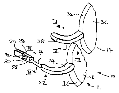
(0010] Figure 1 is a partial perspective view of eyeglasses incorporating
auxiliary frames.
31
21352507.1
2
CA 02491503 2004-12-24
1 [0011] Figure 2 is a view on the line II-II of Figure 1.
2
3 [0012] Figure 3 is a view in the direction of arrow III of Figure 1.
4
[0013] Figure 4 is a view on the line IV of Figure 1.
6
7 [0014] Figure S is a view similar to Figure 1 of an alternative embodiment
of eyeglass.
8
9 [0015] Figure 6 is a view similar to Figure 1 of a still further embodiment
of eyeglass.
11 [0016] Figure 7 is a perspective view from above of the eyeglasses of
Figure 6 in an
12 alternative configuration.
13
14 [0017] Figure 8 is an exploded view of an alternative arrangement of the
eyeglasses of
Figure 1.
16
17 DESCRIPTION OF THE PREFERRED EMBODIMENTS
18
19 [0018] Referring therefore to Figure l, eyeglasses generally indicated by
numeral 10 include
a primary frame assembly 12 and an auxiliary lens assembly 14. The primary
frame assembly 12
21 includes a frame 16 and lenses 18 secured within the frame 16. It will be
appreciated that there
22 are a pair of lenses 16 located within the frame which extends across the
nasal region of the
23 wearer. However, such construction is well known and it is believed
unnecessary to describe in
24 further detail.
26 [0019] Temples 20 extend rearwardly from the primary frame 12 and are
connected to the
27 primary frame through a hinge structure generally indicated by numeral 22.
The hinge structure
28 22 includes an arm 24 secured to the side of the main frame 16. The arm 24
curves rearwardly
29 and is connected to a flexible link 26. The link 26 is made from a shape
memory alloy,
preferably made from a shape memory alloy offering flexibility and high shape
recovery factor.
31 Suitable materials are a nickel-titanium alloy or a copper aluminum alloy,
such as those
21352507.1
3
CA 02491503 2004-12-24
1 disclosed in 5,640,217, the contents of which are incorporated herein by
reference. As can been
2 seen in Figure 4, the link 26 is circular in cross section and extends
between the terminal portion
3 of the arm 24 and a hinge block 28. The link 26 is secured in the arm 24 and
block 28 by an
4 adhesive or other suitable means.
[0020] The hinge block is formed with a clevis 30 to receive a tongue 32
formed at the end
6 of the temples 20. A screw 33 passes through the tongue and clevis to
provide a pivot axis for
7 the temple 20 relative to the main frame 16.
8
9 [0021] The auxiliary lens assembly 14 similarly includes a frame 34 to
secure the auxiliary
lenses, which is of complimentary shape to the frame 16 so that the lenses 36
overly the lenses
11 18. A support arm 38 is secured to the frame 34 and is dimensioned to be of
complimentary
12 shape to and overlie the arm 24. A cavity 40 is formed on the underside of
the arm 38 to receive
13 an L-shaped magnet 42 which generally conforms to the shape of the arm 38.
14
[0022] In use, the arm 38 is positioned over the arm 24 such that the magnet
42 abuts the
16 upper surface of the arm 24. The magnet 42 is attracted to the arm 24 that
is made from
17 magnetisable material and holds the auxiliary lens 14 in situ. The temples
20 may pivot about
18 the screw 33 for storage but when placed on the user, the link 26 permits
flexure of the temple
19 relative to the main frame. The circular cross section of the link 26
provides equal flexure of the
link 26 in all directions and so can accommodate loads imposed on the frame by
external
21 influences. The flexure of the link 26 thus maintains the stability of the
arm 24 and avoids
22 displacement of the arm 24 relative to the support arm 38.
23
24 [0023] Naturally, the link 26 also accommodates flexure during storage and
assists in
maintaining the alignment of the eyeglass assembly 10. If preferred, the arm
24 may have a
26 magnet embedded within it for engagement with magnet of the arm 34, or the
arm 34 may be
27 made from a magnetic material for retention by a magnet in the arm 24. In
each embodiment,
28 the arms 34 is retained on the arm 24 by magnetic attraction. As a further
option as shown in
29 Figure 8, a socket may be formed on one of the arms 24, 34 and a protrusion
52 on the other to
assist in locating the frame assemblies. It is preferred that the protrusion
is a magnet and the
31 socket is magnetic.
21352507.1
4
CA 02491503 2004-12-24
1
2 [0024] An alternative embodiment of eyeglass is shown in Figure 5 in which
like reference
3 numerals will be used to identify like components with a suffix "a" added
for clarity. In the
4 arrangement of Figure 5, the primary frame assembly 12a and hinge assembly
22a are the same
as that shown in Figure 1. The auxiliary lens assembly 14a has a frame 34a
from which an arm
6 38a projects. The frame 34a includes a shroud 50 that projects rearwardly
from the auxiliary
7 lens 36a toward the user. The shroud smoothly merges with the arm 38a to
provide a closely
8 fitting shield to prevent the ingress of incident light around the primary
frame assembly 12a.
9 The arm 38a is secured to the arm 24a by interaction of magnets as described
above.
11 [0025] A further embodiment of eyeglass is shown in Figure 6 and 7 where
like components
12 will be identified with like reference numerals and a suffix "b" added for
clarity. In the
13 embodiment of Figure 6 and 7 the arm 24b is formed as a lateral projection
and the arm 38b
14 similarly formed as a rearwardly extending projection. Link 26b extends
from the block 28b to
the arm 24b and is bent through a right angle in a free body state. This
places the temples in the
16 correct orientation when in use on the user whilst permitting flexure to
accommodate minor
17 variations. The link 26b is circular in cross section thereby allowing
uniform flexure to
18 accommodate distortion between the temple 20b and the main frame 12b. As
may be seen in
19 Figure 7, which shows the configuration with an external load applied to
the temples, the link
26b is sufficiently flexible to allow the temple 20b to extend laterally from
the main frame 12b
21 and to return to a right angle after the load is removed. Again, the magnet
is accommodated in
22 the under surface of the arm 38b so as to be engageable with the upper
surface of the extension
23 24b.
24
[0026] In each embodiment, flexibility is provided between the main frame and
the hinge to
26 accommodate external loads and maintain alignment on the user. At the same
time, a relatively
27 simple hinge may be used and a stable location is provided for attachment
of the auxillary
28 frames.
29
[0027] Although the invention has been described with reference to certain
specific
31 embodiments, various modifications thereof will be apparent to those
skilled in the art without
21352507.1
5
CA 02491503 2004-12-24
departing from the spirit and scope of the invention as outlined in the claims
appended hereto.
2 The entire disclosures of all references recited above are incorporated
herein by reference.
21352507.1
6