Note : Les descriptions sont présentées dans la langue officielle dans laquelle elles ont été soumises.
CA 02492426 2005-O1-12
DESCRIPTION
FUEL CELL
Field of the Invention
The present invention relates to a fuel cell. More particularly, the present
invention
relates to a diffusion electrode of a polymer electrolyte fuel cell.
Background of the Invention
A polymer electrolyte fuel cell (PEFC) includes a membrane-electrode assembly
(MEA) and a separator. At least one layer of the fuel cell forms a module and
a number of
modules are piled.
The MEA includes an electrolyte membrane, a first electrode (an anode)
including a
catalyst layer and a diffusion layer disposed on one side of the electrolyte
membrane, and a
second electrode (a cathode) including a catalyst layer and a diffusion layer
disposed on the
other side of the electrolyte membrane. In separators disposed on opposite
sides of the
MEA, a fuel gas passage for supplying fuel gas (e.g., hydrogen) to the anode
and an oxidant
gas passage for supplying oxygen gas (e.g., oxygen, usually, air) to the
cathode are formed.
In order to cool the fuel cell, a coolant (e.g., water) passage is formed per
one fuel cell or a
plurality of fuel cells in the separators. The separator constructs an
electron current passage
between adjacent fuel cells.
Electrical terminals, electrical insulators, and end plates are disposed at
opposite ends
of the pile of modules. The pile of modules are tightened between the opposite
end plates in
a fuel cell stacking direction and the opposite end plates are coupled to a
fastening member
(for example, a tension plate) extending in the fuel cell stacking direction
outside the pile of
fuel cells, by bolts and nuts to form a stack of fuel cells.
CA 02492426 2005-O1-12
In the PEFC, at the anode, hydrogen is changed to positively charged hydrogen
ions
(i.e., protons) and electrons. The hydrogen ions move through the electrolyte
membrane to
the cathode where the hydrogen ions react with oxygen supplied and electrons
(which are
generated at an anode of the adjacent MEA and move to the cathode of the
instant MEA
through a separator, or which are generated at an anode of a fuel cell located
at a first end of
the pile of fuel cells and move to a cathode of a fuel cell located at a
second, opposite end of
the pile of fuel cells through an external electrical circuit) to form water
as follows:
At the anode: HZ ~ 2H+ + 2e'
At the cathode: 2H+ + 2e + (1/2)Oz ~ H20
Such a conventional PEFC is disclosed in, for example, Japanese Patent
Publication
2002-50367. In the conventional PEFC, usually, the diffusion layer (gas
diffusion layer) is
made from at least one layer of carbon cloth or carbon paper.
However, in the conventional fuel cell, there is the following problem:
Since the diffusion layer made from layered of carbon cloths or carbon papers
is low
in rigidity, and the electrolyte membrane and the catalyst layer are also low
in rigidity, a rib (a
convex of convex and concave portions) of the gas passage of the separator
intrudes on or
pushes into the diffusion layer (see, e.g., region A of FIG. 6), resulting in
a bending
deformation of the diffusion layer and the electrolyte membrane. As a result,
durability of
portions of the diffusion layer and the electrolyte membrane where corners
(shoulders) of the
ribs of the separator contact the diffusion layer decreases, accompanied by a
decrease in
durability of the fuel cell.
In order to increase a rigidity of the diffusion layer thereby preventing the
diffusion
layer from pushing into the membrane due to pressure from the separator, it
might be
effective to make the diffusion layer from a wire netting or a composite
carbon paper (a
CA 02492426 2005-O1-12
composite of carbon and phenol resin.
However, with the wire netting, there are problems of corrosion of the wire
netting,
degradation of the membrane due to the corrosion of the wire netting, and an
increase in a
manufacturing cost. Further, with the composite carbon paper, there is a
problem that a
portion of the diffusion layer compressed by the rib of the separator is
collapsed and gas
cannot flow through the collapsed portion of the diffusion layer.
Summary of the Invention
An object of the present invention is to provide a fuel cell which can prevent
a rib of a
separator from deforming a membrane whereby gas passability of a diffusion
layer can be
kept well.
A fuel cell according to the present invention to achieve the above object is
as
follows:
(1) The fuel cell of the present invention includes a diffusion layer formed
in a sheet
having a small thickness like a membrane. In the fuel cell, there is a tension
imposed on the
sheet in an in-plane direction of the sheet. The tension may act in a
direction substantially
perpendicular to a tightening force associated with assembly of the fuel cell.
(2) In the fuel cell according to item (1) above, the tension is imposed on
the diffusion
layer in a direction perpendicular to a separator gas passage.
(3) In the fuel cell according to item (1) above, the tension is imposed on
the diffusion
layer from a frame disposed outside the fuel cell.
(4) In the fuel cell according to item (1) above, the diffusion layer is fixed
to a separator
by an adhesive with the tension imposed on the sheet.
(5) In the fuel cell according to item (1) above, the tension is of such a
magnitude as to
prevent a portion of the sheet positioned corresponding to a gas passage of a
separator from
CA 02492426 2005-O1-12
being deformed when the fuel cell is tightened.
(6) In the fuel cell according to item (1) above, the tension is adjustable
according to a
fuel cell operating condition.
(7) In the fuel cell according to item (1) above, the tension is adjusted to a
first, small
magnitude during a start-up of the fuel cell from a low temperature and is
adjusted to a
second, large magnitude larger than the first magnitude during a constant
operation of the fuel
cell.
In the fuel cell according to items (1) - (7) above, since a tension directed
in the in-
plane direction of the sheet acts in the sheet in a tightened state of the
fuel cell, a rigidity of
the diffusion layer is increased so that when the diffusion layer is pressed
at a fuel cell
tightening pressure by a separator rib, the rib does not push into or is
unlikely to push into the
diffusion layer and the membrane. As a result, there is no or little damage in
the membrane
due to pressure from the rib. Further, due to an increase in the rigidity due
to the tension,
the diffusion layer is not collapsed beneath the rib. As a result, even if the
tension is
imposed on the diffusion layer, gas passability of the diffusion layer is
maintained well.
In the fuel cell according to item (2) above, since the tension is imposed on
the
diffusion layer in a direction perpendicular to a separator gas passage,
intrusion of the
separator rib into the diffusion layer and the membrane can be effectively
prevented.
In the fuel cell according to items (6) and (7) above, since a magnitude of
the tension
is adjustable according to the fuel cell operating condition, by adjusting the
tension to a small
magnitude during a start-up of the fuel cell from a low temperature, the
electric conductivity
between the diffusion layer and the membrane can be decreased thereby
increasing heat
generation due to an increase in a contact resistance, and by adjusting the
tension to a large
magnitude during a constant fuel cell operation, the electric conductivity
between the
4
CA 02492426 2005-O1-12
diffusion layer and the membrane can be increased.
Brief Description of the Drawings
A fuel cell according to the present invention will now be explained with
reference to
the accompanying drawings, in which:
FIG. 1 is a schematic side elevational view of a stack of fuel cells according
to the
present invention;
FIG. 2 is an enlarged cross-sectional view of a portion of a fuel cell
according to the
present invention;
FIG. 3 is an elevational view of the fuel cell according to the present
invention;
FIG. 4 is a perspective view of a thread and a frame for imposing a tension on
a
textile of a diffusion layer of the fuel cell according to the present
invention;
FIG. 5 is an enlarged cross-sectional view of a portion of the stack of fuel
cells
according to the present invention; and
FIG. 6 is an enlarged cross-sectional view of a portion of a conventional fuel
cell.
Detailed Description of the Preferred Embodiments
With reference to FIGS. 1 - 6 (FIG. 6 illustrates a fuel cell of a comparison
or a
conventional fuel cell), a fuel cell according to the present invention will
be explained below.
The fuel cell according to the present invention is a polymer electrolyte fuel
cell
(PEFC) 10. The fuel cell 10 is mounted to, for example, a vehicle. However,
the fuel cell
may be used in an environment other than a vehicle.
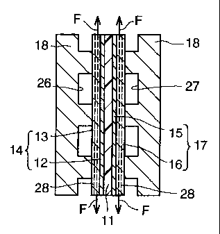
As illustrated in FIGs. 1 and 2, the polymer electrolyte fuel cell 10 includes
a
membrane-electrode assembly (MEA) and a separator 18 layered to the MEA. At
least one
CA 02492426 2005-O1-12
fuel cell forms a fuel cell module 19, and a plurality of fuel cell modules
are piled.
The MEA includes an electrolyte membrane 11 made from an ion exchange
membrane, a first diffusion electrode 14 (anode) including a catalyst layer 12
and a diffusion
layer 13 disposed on one side of the electrolyte membrane, and a second
diffusion electrode
17 (cathode) including a catalyst layer 15 and a diffusion layer 16 disposed
on the other side
of the electrolyte membrane.
Electrical terminals (terminal plates) 20, electrical insulators 21, and end
plates 22 are
disposed at opposite ends of the pile of fuel cell modules. The end plates are
coupled by
bolts 25 to fastening members (for example, tension plates 24) which extend in
a longitudinal
direction (fuel cell module piling direction) of the pile of fuel cell modules
outside the pile of
the fuel cell modules, and the fuel cell modules are tightened in the
longitudinal direction of
the pile of fuel cell modules and, together with the members 20, 21, 22 and
24, construct a
fuel cell stack 23.
In an anode-side separator of a pair of separators opposing each other via the
MEA, a
fuel gas passage 26 for supplying fuel gas (e.g., hydrogen) to the anode 12 is
formed. In a
cathode-side separator of the pair of separators opposing each other via the
MEA, an oxidant
gas passage 27 for supplying oxidant gas (e.g., oxygen, usually, air) to the
cathode 14 is
formed. Further, in the separator 18, a coolant passage for cooling the fuel
cell is formed
each fuel cell or each plurality of fuel cells. For example, in FIG. 2, the
coolant passage is
formed in a surface of the separator 18 opposite an MEA contacting surface of
the separator.
The separator 18 separates the coolant from the fuel gas or the oxidant gas,
or separates the
fuel gas from the oxidant gas. The separator 18 operates as an electricity
current passage
between the anode and the cathode of adjacent fuel cells.
When the diffusion layers opposing each other via the separator are
electrically
conductive by use of a conductive member 31 to connect the diffusion layers as
illustrated in
CA 02492426 2005-O1-12
FIG. 5, the separator 18 can be non-conductive.
The diffusion layer 13 is formed in a sheet having a small thickness like a
membrane
(a thin sheet). The catalyst layer 12 can be coated on an MEA opposing surface
of the
diffusion layer 13 so that the catalyst layer 12 and the diffusion layer 13
form the thin sheet,
or the catalyst layer 12 can be coated on the membrane 11 so that the
diffusion layer 13 is a
layer separate from the catalyst layer 12.
Similarly, the diffusion layer 16 is formed in a sheet having a small
thickness like a
membrane (a thin sheet). The catalyst layer 15 can be coated on an MEA
opposing surface
of the diffusion layer 16 so that the catalyst layer 15 and the diffusion
layer 16 form the thin
sheet, or the catalyst layer 15 can be coated on the membrane 11 so that the
diffusion layer 16
is a layer separate from the catalyst layer 15.
As illustrated in FIG. 2, a tension (tension force) F of a specified magnitude
directed
in an in-plane direction of the sheet (a direction parallel to a major surface
of the sheet) is
applied in a fuel cell assembled and tightened as described above. The fuel
cell stack is
tightened keeping the state where the tension F acts in the diffusion layer
13, 16. This
condition that "the fuel cell stack is tightened keeping the state where the
tension F acts in the
diffusion layer 13, 16" includes a case where, in keeping the state where the
tension F is
imposed on the diffusion layer 13, 16, the diffusion layer 13, 16 is fixed to
a separator 18 by
an adhesive, and then the separator fixed with the diffusion layer 13, 16 and
the membrane 11
or the MEA are layered and are tightened.
FIG. 5 illustrates a state where the fuel cell modules 19 are layered in a
longitudinal
direction of a pile of fuel cell modules and a tightening load is not yet
imposed on the pile of
fuel cell modules. FIG. 2 illustrates a state where a tightening load is
imposed on the pile of
fuel cell modules. FIG. 2 illustrates a portion of one fuel cell module in an
enlarged cross
CA 02492426 2005-O1-12
section.
In the case where the diffusion layers 13 and 16 opposing each other via the
separator
18 are electrically connected to each other by a conductive member 31, the
separator 18 can
be electrically non-conductive.
The tension is imposed on the diffusion layer 13, 16 in a direction
perpendicular to the
gas passage 26, 27 formed in the separator 18 which the diffusion layer 13, 16
contacts. For
example, in FIG. 3, when the gas passage 26, 27 extends in a right and left
direction of FIG. 3,
the tension F directed in an up-and-down direction of FIG. 3 is imposed on the
diffusion layer
13, 16.
One example of a method of imposing the tension on the diffusion layer 13, 16
is
illustrated in FIGS. 4 and 5. In the method, opposite ends of threads (e.g.,
carbon threads)
28 constituting a textile of the sheet of diffusion layer 13, 16 are fixed to
(e.g., bound to or
bonded to) frames 29 (an upper frame and a lower frame) disposed outside the
fuel cell, and
by moving the frames 29 in a direction away from each other by using a support
pole 30 to
separate the frames 29 so that a tension is imposed on the diffusion layer 13,
16. More
particularly, a right-hand thread is formed in one end portion of the support
pole and a left-
hand thread is formed in the other end portion of the support pole, and by
rotating the support
pole about an axis of the support pole, the frames 29 are moved in a direction
away from each
other or closer to each other. By rotating the support pole 30 in such a
rotational direction
as to move the frames 29 away from each other, the frames are moved apart so
that the
tension is imposed on the diffusion layer 13, 16. When the tension force
imposed on the
diffusion layer 13, 16 is directed in an up-and-down direction in FIG. 3, the
threads on which
the tension is imposed are directed in the up-and-down direction in FIG. 3.
When the threads 28 are bound to the frame 29, as illustrated in FIG. 4,
preferably,
knots or expanded portions 32 are formed in opposite ends of some or all of
the threads 28.
CA 02492426 2005-O1-12
Then, letting portions of the threads other than the knots or expanded
portions extend through
the slits or holes formed in the frames 29 and letting the knots or expanded
portions 32
engage outboard surfaces of the frames 29, the threads 28 can be fixed to the
frames 29 and
extend in a direction of the applied tension.
The tension imposed on the diffusion layer 13, 16 is of such a magnitude as to
prevent
a portion of the sheet positioned corresponding to a gas passage of a
separator from being
deformed, that is, the tension prevents the ribs of the gas passage of the
separator 18 from
pushing into the membrane 11, when the fuel cell is tightened.
The tension F imposed on the diffusion layer 13, 16 may be adjustable
according to an
operating condition of the fuel cell. It is easy to adjust the tension F in
the case where the
threads 28 are bound to the frames 29.
When the tension F is adjusted according to the fuel cell operating condition,
it is
preferable that the tension is adjusted to a first, small magnitude during a
start-up of the fuel
cell from a low temperature and the tension is adjusted to a second, large
magnitude larger
than the first magnitude during a constant operation of the fuel cell.
FIG. 6 illustrates a conventional state where a tension is not imposed on a
diffusion
layer. FIG. 2 illustrates a state according to the present invention where the
tension is
imposed on the diffusion layer.
In the state where the tension is small, the state according to the present
invention
becomes close to the state of FIG. 6. In the state where the tension is small,
a contact
pressure between the diffusion layer 13, 16 and a rib of the separator 18 is
small so that the
electric conductivity of the electrode diffusion layer 13, 16 decreases
whereby heat
generation is promoted, and the electrode diffusion layer 13, 16 is deformed
in a direction
away from the membrane 11 at a portion where the electrode diffusion layer 13,
16 is not
pressed by the separator rib (see, e.g., region A of FIG. 6) and a heat is
collected in that
CA 02492426 2005-O1-12
portion. As a result, the fuel cell is smoothly activated during start-up of
the fuel cell from a
low temperature and can be smoothly shifted to a constant output operation.
In the constant operation of the fuel cell where the tension is large, as
illustrated in
FIG. 2, a rigidity of the electrode diffusion layer 13, 16 is large, so that a
rib of the separator
18 does not push into and deform the diffusion layer 13, 16 and the membrane
11, and the
contact pressure between the diffusion layer and the separator rib is large
whereby the
conductivity is improved.
Effects of the fuel cell according to the present invention will now be
explained.
Since the tension F is imposed on the diffusion layer 13, 16, as illustrated
in FIG. 2,
the rigidity of the electrode diffusion layer is increased. As a result, the
separator rib is
unlikely to push into the electrode diffusion layer 13, 16 and the membrane
11, and damage
to the membrane 11 at a portion corresponding to the shoulder corner of the
separator rib (a
portion A in FIG. 6) is reduced. If the membrane 11 is damaged, the fuel gas
leaks into the
oxidant gas and is oxidized to generate heat to further damage the membrane
11. Contrarily,
in the present invention, since little damage occurs in the membrane 11, such
leakage of the
fuel gas and heat generation due to the leakage do not occur. As a result,
durability of the
fuel cell is improved.
Since the improvement of the durability of the fuel cell is performed by
imposing the
tension on the diffusion layer 13, 16, a density of the diffusion layer 13, 16
does not need to
be raised. Further, since the separator rib is unlikely to push into the
diffusion layer 13, 16,
the density of the portion of the diffusion layer beneath the separator rib is
not raised due to
being collapsed from the pressure of the separator rib. As a result, gas
passability of the
diffusion layer 13, 16 is equal to or better than a gas passability of the
convention diffusion
layer.
CA 02492426 2005-O1-12
Since the tension F is imposed on the diffusion layer 13, 16 in the direction
perpendicular to the gas passage 26, 27 formed in the separator when the
tension F is
imposed on the diffusion layer 13, 16, a portion of the diffusion layer 13, 16
between adjacent
ribs of the separator is unlikely to be deformed so as to be pushed into the
gas passage of the
separator, so that the separator rib is unlikely to push into the diffusion
layer 13, 16. As a
result, the above-described intrusion of the rib into the diffusion layer and
damage of the
membrane 11 are effectively prevented.
Further, since the diffusion layer 13, 16 is tensioned from the frame 29
disposed
outside the fuel cell, a structure in the fuel cell does not need to be
changed. Further, when
imposing the tension on the diffusion layer 13, 16 by pulling the frames 29
outside the fuel
cell in a direction apart from each other, imposing the tension and changing
the magnitude of
the tension can be performed in a simple procedure.
Further, in the case where the tension is adjustable and the tension is made
small
during a start-up of the fuel cell from a low temperature, a start-up from a
low temperature
(for example, about - 40~ ) becomes smooth.
APPLICABILITY TO THE INDUSTRY AND ADVANTAGES OF THE INVENTION
The tensioned diffusion layer according to the present invention is applicable
to a fuel
cell.
More particularly, since the tension having a suitable magnitude is imposed on
the
sheet of the diffusion layer in the in-plane direction of the sheet, the
rigidity of the diffusion
layer is increased. As a result, when the diffusion layer is pressed by the
separator rib at the
fuel cell tightening pressure, the rib does not or only slightly pushes into
the diffusion layer
and the membrane, and there is no or little damage to the membrane. Further,
since the
rigidity of the diffusion layer is increased due to the tension, the diffusion
layer is not
CA 02492426 2005-O1-12
collapsed to a solid layer. As a result, despite the load imposed on the
diffusion layer, gas
passability of the diffusion layer is maintained well.
In the case where the tension is imposed on the diffusion layer in the
direction
perpendicular to the separator gas passage, intrusion of the separator rib
into the diffusion
layer and the membrane is effectively prevented.
In the case where the tension is imposed on the diffusion layer from the frame
disposed outside the fuel cell, the tension force can be imposed on the
diffusion layer without
changing the interior structure of the fuel cell. In addition, adjusting the
tension imposed on
the diffusion layer is easy.
In the case where the diffusion layer is fixed to the separator by an adhesive
while the
tension is imposed on the diffusion layer, the tension force can be imposed on
the diffusion
layer without changing the interior structure of the fuel cell.
In the case where the tension is of such a magnitude as to prevent a portion
of the
sheet positioned corresponding to the gas passage of the separator from being
deformed when
the fuel cell is tightened, the rigidity of the diffusion layer can be
increased without breaking
the sheet of the diffusion layer.
In the case where the tension is adjustable according to the fuel cell
operating
condition, by adjusting the tension to a small magnitude during a start-up of
the fuel cell from
a low temperature, the electric conductivity between the diffusion layer and
the membrane
can be decreased thereby increasing heat generation due to an increase in a
contact resistance,
and by adjusting the tension to a large magnitude during a constant fuel cell
operation, the
electric conductivity between the diffusion layer and the membrane can be
increased.
12