Note : Les descriptions sont présentées dans la langue officielle dans laquelle elles ont été soumises.
CA 02492464 2006-11-22
1
SWIMMING POOL CLEANING APPARATUS
Field of the Invention
The present invention generally relates to self propelled swimming pool
cleaners for cleaning submerged surfaces, and more particularly to a swimming
pool
cleaning apparatus incorporating a flow control valve for establishing
intermittent flow
of a fluid through the cleaner for causing the cleaner to travel across the
surface to
be cleaned.
Background of the Invention
Submersible pool cleaners employing oscillating valves within a housing and
flexible discs engaging the surface to be cleaned are generally well known, as
illustrated by way of example with reference to U.S. Patent Nos. 4,023,227 to
Chauvier and 4,351,077 to Hofmann. What is also generally known are the
problems associated with debris clogging fluid flow passages, wearing cleaner
components rendering the cleaner ineffective or unusable, and the difficulty
for a
consumer attempting to replace such worn components. Embodiments of the
present invention herein described provide an efficiently run submersible
cleaner
which includes components that are easily replaceable by the consumer.
Summary of the Invention
A submersible cleaner in keeping with the teachings of the present invention
may include a housing moveable along a submerged surface to be cleaned through
fluid flow past a valve operable for moving the cleaner. The housing may
include a
flow passage for a flow of fluid and debris from an inlet to an outlet with
the fluid and
debris constrained to flow through an opening defined within the passage. A
wall
may extend into the flow passage for defining the opening. A valve may be
operable
within the flow passage for interrupting fluid flow. An element acting between
the
valve distal end and the wall reduces a gap formed between them. The element
may be attached to either the valve or the wall, and may make slidable
engagement
with the wall or the valve distal end. The element as herein referenced is
generally
retractable from or moveable away from the wall surface with which it operates
and
CA 02492464 2006-11-22
2
may be described as retractable, pivotable, or flexible and may or may not
fully close
the gap.
A flexible plate may be carried proximate the inlet for engaging the surface
to
be cleaned. The flexible plate may be described to include an upper surface,
an
opposing lower surface for contacting the surface to be cleaned, and a
periphery
defined by a plurality of tongues radially extending about the periphery. Each
of the
plurality of tongues may include a lower surface portion for contacting the
surface to
be cleaned and a contouring portion in a spaced relation with the surface to
be
cleaned during operation of the apparatus, thus upwardly lifting an outer most
periphery of the plate from the surface to be cleaned. A plurality of
reinforcing
elements may be integrally formed with the flexible plate for upwardly
contouring the
periphery from the surface to be cleaned. The reinforcing elements may include
a
rib that may be integrally formed with the upper surface of the flexible plate
with the
rib extending radially outward while confined within the periphery of the
flexible plate.
Alternatively, the reinforcing element may comprise a flange extending along
the
peripheral edge of the tongue, or yet other reinforcing styled elements.
Brief Description of the Drawings
Embodiments of the invention are described by way of example with
reference to the accompanying drawings in which:
FIG. 1 is a left side perspective view of one embodiment of a swimming pool
cleaner according to the present invention;
FIG. 2 is a right side elevation view of the cleaner of FIG. 1;
FIG. 3 is a partial cross section view of a pool cleaner illustrating fluid
flow
therethrough;
FIGS. 4 and 5 are partial cross section view of a housing portion of the
embodiment of FIG. 3 illustrating an enlarged view of the oscillator valve in
a seated
position and an unseated position, respectively;
FIGS. 6 is an alternate embodiment of the valve in keeping with the teachings
of the present invention;
FIG. 7 is a perspective view of a cover;
FIGS. 8 and 9 are perspective and side views of an embodiment of a valve;
FIG. 10 is a partial top view looking down on the valve carried within the
housing;
CA 02492464 2005-01-13
WO 2004/007872 PCT/US2003/022154
3
FIG. 11 and 11A illustrate alternate embodiments having a retractable
element carried by the valve and alternatively by a partition wall,
respectively;
FIGS. 13-20 illustrate alternate embodiments of the valve operable with the
retractable element;
FIG. 21 is a partial top view of one embodiment of a flexible plate;
FIG. 22 is a partial cross section elevation view taken through lines 22-22 of
FIG. 21;
FIG. 23 is a partial top view of one embodiment of a flexible plate;
FIG. 24 is a partial cross section elevation view taken through lines 24-24 of
FIG.23;
FIG. 25 is a top plan view of one embodiment of a flexible plate;
FIG. 26 is a top plan view of an alternate embodiment of a flexible plate;
FIG. 27 is a partial top view of one embodiment of a flexible plate;
FIG. 28 is a partial cross section elevation view taken through lines 28-28 of
FIG.27;
FIG. 29 is a partial cross section view taken through lines 29-29 of FIG. 27;
FIG. 30 is an elevation and partial cross section view of a footpad of FIG. 1;
FIG. 31 is a side elevation and partial cross section view of the footpad of
FIG. 30 illustrating front and rear lateral inlet ports; and
FIG. 32 is an elevation view of the footpad of FIG. 30 illustrating dual
lateral
inlet ports.
Detailed Description of the Preferred Embodiments
Embodiments of the present invention will now be described more fully with
reference to the accompanying drawings. It will be understood by those skilled
in the
art that this invention may be embodied in many different forms and should not
be
construed as limited to the embodiments set forth herein. Rather, these
embodiments are provided so that this disclosure will be thorough and
complete, and
will fully convey the scope of the invention to those skilled in the art. Like
numerals
refer to like elements.
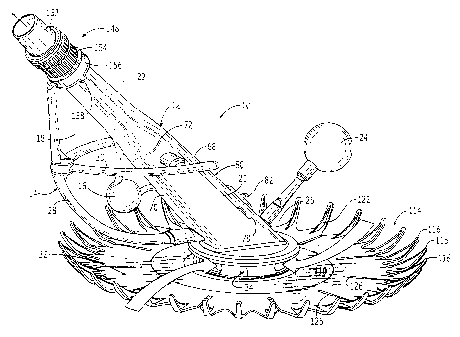
With reference initially to FIGS. 1 and 2, an embodiment of the present
invention is herein described, by way of example, for a submersible swimming
pool
cleaner 10 having a housing 12 inclined toward a direction of travel, which
housing
carries a bumper 14 and weight 16 about a forward portion 18 with the bumper
CA 02492464 2006-11-22
-1
extending to left and right side portions 20, 22. A float 24 is carried at an
aft portion
26 for acting in conjunction with the weight 16 in allowing the cleaner 10 to
fall to an
upright posftion when dropping from a sidewall of a swimming pool. Vertical
and
horizontal bumper members 28, 30 are effective in having the cleaner avoid
obstructions within the swimming pool, such as steps and sharp corners. The
housing 12 further carries a flexible plate 32 via attachment with a footpad
34.
The housing 12 includes a single flow passage 36 extending from an inlet 38
to an outlet 40 for a flow of fluid and debris through the passage, as
described with
reference to FIG. 3. A partition waif 42 extends into the single flow passage
36 such
that the flow of fluid and debris (illustrated with arrows 44) are constrained
to pass
through an opening 46 formed thereby and pass to the outlet 40, which outlet
is
adapted for connection to a suction source 48. The flexible plate 32 is
carried about
the inlet 38 for engaging a submerged surface 50 to be cleaned. A valve 52 is
pivotally carried within the flow passage 36 for interrupting fluid flow 44
through the
passage during an oscillation of the valve between a seated position 54 for
interrupting the flow to an unseated position 56 permitting the flow, as
illustrated with
reference to FIGS. 4 and 5. The valve 52 interrupts flow through the passage
36
resulting in a motion of the inclined housing 12 causing it to travel along
the surface
of the pool to be cleaned, the valve thus acting as the "motor" for the pool
cleaner.
With continued reference to FIG. 3, a suction of the fluid through the flow
passage 36
causes an oscillating of the valve between the seated and the unseated
positions
and a resulting movement of the cleaner 10 across the submerged surface 50.
With continued reference to FIGS. 3-5, An element 58 acts between a valve
distal end 60 and a surface 62 of the partition wall 42 for reducing a gap 64
formed
between them, thus substantially limiting the flow of the fluid and debris to
only one
side 66 of the valve 52. For the embodiment herein illustrated by way of
example in
FIGS. 3-5, the element 58 is herein referenced to as a retractable element 58
and
may be dimensioned such that the fluid flow through the passage 36 causes the
retractable element to have slidable engagement between the valve distal end
60
and the surface 62 of the partition wall 42 during the oscillation of the
valve, as
illustrated with reference again to FIGS. 4 and 5, or alternatively may fully
close or
simply reduce the size of the gap 64, as illustrated with reference to FIG. 6.
CA 02492464 2006-11-22
With reference again to FIGS. 1-5, the single flow passage 36 may be defined
by opposing top and bottom walls 68, 70 in combination with opposing left and
right
sidewalls 72, 74, wherein the distal end 60 of the valve 52 contacts the
bottom wall
70 in the seated position 54 and oscillates between the seated position and a
stop
76 formed with the distal end 60 for contacting the top wall 68.
As illustrated with reference again to FIGS. 1-5, an access opening 78 within
the top wall 68 provides entry into the housing 12 and the flow passage 36. A
detachable cover 80 encloses the opening 78. Access to the flow passage
provides
a convenience when clearing out debris lodged therein or replacing the valve,
by
way of example. In one embodiment of the cleaner, as herein described by way
of
example, the partition wall 42 is integrally formed with the cover 80, as
further
illustrated with reference to FIG. 7. The cover 80 includes a lock 82 and tab
84
located at ends of the cover for securing the cover to the housing 12 for
covering the
opening 78. A pivot pin 86 is carried by the housing 12 for pivotal connection
with a
proximal end 88 of the valve 52. As illustrated with reference again top FIGS.
4 and
5, the valve 52 may be constructed to include an elongate arm 90 having the
proximal end 88 for connection to the pivot pin 86. A head portion 92 is
located at the
valve distal end 60. The distal end 60 is carried within the passage 36
upstream the
proximal end 88. In the em))odiment illustrated with reference to FIGS. 4 and
5, by
way of example, the head portion 92 includes a slot 94 for slidably receiving
the
retractable element 58. One embodiment of the retractable element 58 includes
a
slit 96 that is operable with a pin 98 carried within the slot 94, as
illustrated with
reference to FIGS. 8 and 9. Flexible side edges 100 extend along the
longitudinal
sides of the valve 52 for minimizing side gaps 102 on the sides of the valve
and for
providing a close fit, as further illustrated with reference to FIG. 10, thus
enhancing
control of the fluid flow along the one side 66 of the valve 52, as earlier
described
with reference to FIGS. 3-5.
Alternate embodiments keeping within the teachings of the present invention,
may include by way of example, the head portion 92 having a protrusion 104
extending radially outward from the valve distal end 60 for slidably receiving
the
retractable element 58, as illustrated with to reference to FIG. 11. Further,
the
partition wall 42 may include a slot 106 extending for slidably receiving the
retractable element 58, as illustrated with reference to FIG. 12. Yet further,
the
partition wall 42 may include a protrusion 108 extending outward toward the
valve 52
for slidably receiving the retractable element 58, as illustrated by way of
further
CA 02492464 2006-11-22
6
example with reference to FIG. 1 1A. As herein illustrated, the element 58 may
have
various shapes and may be attached to the valve 52 or to the partition wall 42
without deviating from the teachings of the present invention, and may or may
not
fully close the gap 64, as illustrated with reference to FIGS. 13-20. Element
58 may
be viewed as retracting, pivoting, or flexing as a form of retracting.
By way of further example with reference to FIG. 15, the element 58 may
have one end 58a fixedly attached to the valve head portion 92 at a distal end
92a
thereof. The element 58 may be dimensioned for reducing the gap 64 without
contacting the wall 42 as illustrated with reference again to FIG. 6.
Alternatively, and
with continued reference to FIG. 15, a free end 58b of the element 58 may
contact
the surface of the wall 42 and sweep across the surface of the wall 42 as the
valve
52 oscillates during operation of the pool cleaner. Such sweeping movement
causes the element 58 to flex and effectively retract from the wafl 42, or
alternatively
from the valve 52 as illustrated with reference to FIG. 16 where the free end
58b
sweeps around an end surface of the valve 52.
With reference to FIGS. 19 and 20, by way of example, the generally circular
cross sectional shape of the retractable element 58 and carried within a
generally
arcuate shape for the slot 94 supports a rolling motion for the retractable
element
during movement of the head portion 92, thus reducing wear of the surface and
element while remaining effective in directing fluid flow to the one side 66
of the
valve 52. The element 58 is movably carried within the slot 94 making
continuous contact with the 62 of the partition wall 42 or in close proximity
as herein
described. With reference again to FIGS. 6, 12, and 17, an embodiment of the
valve
52 includes the head portion 92 having an angled slot 94 tapering from outside
toward a slotted hole 95, or alternatively having the tapered slot within the
partition
wall as illustrated with reference to FIG. 18. The head contact element
includes an
elongate portion having one end extending out of the slot 94 and an opposing
end
having a bulbous portion for a sliding movement within the hole 95. Such an
embodiment allows the retractable element 58 to be secured within the slot 94
during
installation and easily held therein during assembly of the valve. Further, a
flexible
arm portion 109 may be provided as a shock buffer that results in reducing
noise
generated by the oscillating valve 52, as illustrated with reference again to
FIG. 6.
CA 02492464 2006-11-22
6a
With reference again to FIGS. 1-3, the flexible plate 32 may be described as
having an upper surface 110 and an opposing lower surface 112 for contacting
the
surface to be cleaned 50. A periphery 114 of the plate 32 includes a plurality
of
tongues 116 radially extending thereabout. Each tongue 116 includes a lower
surface portion 118 for contacting the surface to be cfeaned 50 and a
contoured
portion 120 in a spaced relation with the surface to be cleaned during
operation of
the cleaner 10, as illustrated with reference again to FIG. 3, and to FIGS. 21
and 22,
the outer most peripheral portion of the plate being upwardly lifted from the
surface
to be cleaned. In one embodiment, as herein illustrated, a rib 122 is
integrally
formed with the upper surface 110 of the flexible plate 32 at the tongue 116.
The rib
122 reinforces the tongue 116 for securing the contoured portion 120 in the
convex
shape. Alternate reinforcing element shapes may be formed with the flexible
plate
32 for upwardly contouring the periphery 114 upwardly from the surFace to be
cleaned 50, including a flange 124 extending along a peripheral edge of the
tongue,
as illustrated by way of example with reference to FIGS. 23 and 24.
CA 02492464 2005-01-13
WO 2004/007872 PCT/US2003/022154
7
As illustrates with reference again to FIG. 2 and to FIG. 25, embodiments of
the plate 32 may include slots 126 radially extending from a center 128 of the
plate.
The slot 126 herein described is tapered so as to provide a diminishing gap as
the
taper extends radially outward from the center 128. Alternatively, the plate
32 may
include a slit 130, as illustrated with reference again to FIGS. 22 and 24.
Yet further,
a combination of tapered slot 126 and slit 130 may be formed within the plate
32, as
illustrated with reference to FIG. 26, such slots and slits extending radially
outward
from the center 128 of the plate 32 provide added flexibility to the flexible
plate 32
and improved maneuverability over contours within the surface to be cleaned
50. A
plurality of slots or slit may be symmetrically located as herein illustrated
or located
as desired for surface conditions.
By way of further example, and as illustrated with reference again to FIG. 25,
the plurality of slots may extend along a first imaginary line 132 centrally
positioned
between second imaginary lines 134 passing centrally through each of the
plurality
of tongues 116. Further, the plate 32 may include grooves 136 within the lower
surface 112 and extending radially outward for the center 128. As illustrated,
the
grooves 136 may extend only partially between the center 128 and the periphery
114
of the plate 32.
Pleats 138 provide yet another alternative for adding flexibility to the plate
32,
as illustrated with reference FIGS. 27-29. Each of a plurality of pleats 138
extending
radially from the center 128 forms a groove 140 within the lower surface 112
and a
protrusion 142 in the upper surface 110.
With reference to FIG. 26, by way of example, the plate 32 may include a
plurality of holes 144 extending from the upper surface 110 to the lower
surface 112
for modifying a suction provided by the flexible plate during operation of the
cleaner
10 with the suction source.
As earlier described with reference to FIGS. 1-3, the cleaner 10 herein
described by way of example, includes a foot pad 34 which carries the plate
32. The
foot pad 34 is attached to a flange 146 at the inlet 38 of the housing 12 as
further
illustrated with reference to FIG. 30. The footpad 34 is attached to the
housing 12
and the flexible plate 32, and easily replaced by the consumer. As illustrated
with
reference to FIGS. 31 and 32 using arrows, fluid flow passes through openings
within the footpad above the plate and below for providing an effective
cleaning of
debris from the surface to be cleaned. As illustrated with reference again to
FIG. 1-
CA 02492464 2005-01-13
WO 2004/007872 PCT/US2003/022154
8
3, a hose connector 148 is carried at the outlet 40 of the housing 12. Under
the
influence of the vacuum source 48, typically a pump, a flexible hose 150
connected
to the connector 148 causes fluid and debris to flow through the housing 12.
As illustrated with reference again to FIGS. 1-3, one embodiment of the hose
connector 148 includes a swivel portion 152, nut portion 154 and collar 156
for
providing a swivel connection to the hose 150. Such a combination permits easy
replacement of parts. A key 158 is carried by the collar 156 to fix the bumper
14 in a
forward position.
Various embodiments of the present invention have been herein described in
the drawings and specification, by way of example. Although specific
terminology
was employed, the terms are used in a descriptive sense only and not for
purposes
of limitation. The invention has been described in detail with specific
reference to
these illustrated embodiments. However, it will be apparent that various
modifications and changes may be made while keeping within the teachings and
scope of the invention as described in the foregoing specification and as
defined in
claims.