Note : Les descriptions sont présentées dans la langue officielle dans laquelle elles ont été soumises.
CA 02492656 1997-10-O1
LOCAL DEVICE AND PROCESS DIAGNOSTICS IN A PROCESS CONTROL
NETWORK HAVING DISTRIBUTED CONTROL FUNCTIONS.
This application is a division of Canadian Patent Application No. 2,267,527
filed on
October 1, 1997 and entitled LOCAL DEVICE AND PROCESS DIAGNOSTICS IN A
PROCESS CONTROL NETWORK HAVING DISTRIBUTED CONTROL FUNCTIONS.
FIELD OF THE INVENTION
The present invention relates generally to process control networks and, more
specifically, to a method of and an apparatus for performing local device and
process
diagnostics in a process control network having distributed control functions.
DESCRIPTION OF THE RELATED ART
Large processes such as chemical, petroleum, and other manufacturing and
refining
processes include numerous filed devices disposed at various locations to
measure and
control parameters of the process to thereby effect control of the process.
These field devices
may be, for example, sensors such as temperature, pressure, and flow rate
sensors as well as
control elements such as valves and switches.
Historically, the process control industry used manual operations like
manually
reading level and pressure gauges, turning valve wheels, etc., to operate the
measurement and
control field devices within a process. Beginning in the 10th century, the
process control
industry began using local pneumatic control, in which local pneumatic
controllers,
transmitters, and valve positioners were placed at various locations within a
process plant to
effect control of certain plant locations. With the emergence of the
microprocessor-based
distributed control system (DCS) in the 1970's, distributed electronic process
control became
prevalent in the process control industry.
As is known, a DCS includes an analog or a digital computer, such as a
programmable logic controller, connected to numerous electronic monitoring and
control
devices, such as electronic sensors, transmitters, current-to-pressure
transducers, valve
positioners, etc. located throughout a process. The DCS computer stores and
implements a
centralized and, frequently, complex control scheme to effect measurement and
control of
devices within the process to thereby
CA 02492656 1997-10-O1
.,
control process parameters according to some overall control scheme. Usually,
however, the control scheme implemented by a DCS is proprietary to the DCS
controller manufacturer which, in turn, makes the DCS difficult and expensive
to
expand, upgrade, reprogram, and service because the DCS provider must become
involved in an integral way to perform any of these activities. Furthermore,
the
equipment that can be used by or connected within any particular DCS may be
limited due to the proprietary nature of DCS controller and the fact that a
DCS
controller provider may not support certain devices or functions of devices
manufactured by other vendors.
To overcome some of the problems inherent in the use of proprietary
DCSs, the process control industry has developed a number of standard, open
communication protocols including, for example, the HART~, PROFIBUS~,
WORLDFIP~, LONWORKS~, Device-Net~, and CAN protocols, which enable
field devices made by different manufacturers to be used together within the
same
process control network. In fact, any field device that conforms to one of
these
protocols can be used within a process to communicate with and to be
controlled
by a DCS controller or other controller that supports the protocol, even if
that
field device is made by a different manufacturer than the manufacturer of the
DCS
controller.
Moreover, there is now a move within the process control industry to
decentralize process control and, thereby, simplify DCS controllers or
eliminate
the need for DCS controllers to a large extent. Decentralized control is
obtained
by having process control devices, such as valve positioners, transmitters,
etc.
perform one or more process control functions and by then communicating data
across a bus structure for use by other process control devices in performing
other
control functions. To implement these control functions, each process control
device includes a microprocessor capable of performing one or more control
functions as well as communicating with other process control devices using a
standard and open communication protocol. In this manner, field devices made
by
different manufacturers can be interconnected within a process control network
to
-2-
CA 02492656 1997-10-O1
communicate with one another and to perform one or more process control
functions forming a control loop without the intervention of a DCS controller.
The all-digital, two-wire bus protocol now being promulgated by the Fieldbus
Foundation, known as the FOUNDATIONTM Fieldbus (hereinafter "Fieldbus")
protocol is one open communication protocol that allows devices made by
different
manufacturers to interoperate and communicate with one another via a standard
bus to effect decentralized control within a process.
As noted above, the decentralization of process control functions simplifies
and, in some cases, eliminates the necessity of a proprietary DCS controller
which, in turn, reduces the need of a process operator to rely on the
manufacturer
of the DCS controller to change or upgrade a control scheme implemented by the
DCS controller. However, decentralized control also makes it more difficult to
perform diagnostics, such as process diagnostics, which are typically
performed by
a DCS controller. Performing regular diagnostics, such as device and process
diagnostics, is very important, however, when using field devices such as
fluid
control valves in harsh environments in which, for example, temperature and
pressure ranges are widely variable. In such environments, substantial
maintenance, including periodic preventative maintenance, maintenance due to
valve breakdown, and testing to verify that valves are ftinctioning properly,
is
necessary.
In a standard DCS environment, a computer (such as a personal computer)
is coupled to the network and performs device diagnostics on, for example, a
valve or a posidoner/valve combination, by sending a diagnostic control signal
to
the positioner, which then forces the valve through a test stroke or test
cycle
associated with the diagnostic control signal. During this time, the computer
measures outputs of the positioner and/or the valve, such as changes in valve
position, that occur in response to the diagnostic control signal and,
thereafter,
performs analysis on the measured outputs to determine the operating condition
of
the valve or the positioner/valve device.
-3-
CA 02492656 1997-10-O1
In one known diagnostic system for fluid control valves, such as
pneumatically actuated valves, a pressure sensor is provided to sense varying
pressure at the input of a valve and a position sensor is provided to sense
the
movement of a valve plug. The valve is operated through a test operation cycle
by supplying a controlled variable pneumatic pressure to the input terminal of
a
pneumatic valve. During, for example, the test operation cycle of a dynamic
scan,
the valve plug is moved through a desired range, normally from a fully opened
position to a fully closed position and returned from the fully closed
position to the
fully opened position. Alternatively, step tests may move the valve plug in a
series of individual steps to test certain valve parameters.
During the test operation cycle, the pressure sensor provides an output
signal that corresponds to varying pressure at the valve input, and the
position
sensor provides an input signal corresponding to the movement of the valve
plug.
The respective input or output signals of the air pressure at the actuator and
the
valve plug or valve stem position are then processed to derive data
representing
the variation in pressure at the valve input as a function of movement of the
valve
plug during the test operation cycle. The valve stem load is derived by
multiplying the air pressure times the effective area of the actuator
diaphragm.
The diagnostic system receives the diagnostic commands and communicates
the diagnostic information obtained from the sensors via a communication line
to
an external control console or processor/computer. The external control
console
or processor/computer requests a single diagnostic test and waits for a result
while
the diagnostic system performs the test. When the test is complete, the
diagnostic
system sends the test result to the external control console. Many various
diagnostic tests are performed for each valve and a control system generally
includes many valves so that diagnostic test time can be lengthy.
As is also known, in a standard DCS environment, a computer such as a
DCS controller performs process diagnostics using, for example, a valve or a
positioner/valve combination, by sending a diagnostic control signal to the
posidoner, which then forces the valve through a test sequence.
-4-
CA 02492656 1997-10-O1
In a standard DCS environment, device or process diagnostics can be
performed without rewiring or reconfiguring the system to a significant extent
because the DCS controller or the external computer is already configured to
control the set points (or other inputs) of the various devices within the
process
and to measure device outputs and other process parameters to implement a
control strategy associated with the normal operation of the process. As a
result,
performing diagnostics in a standard DCS environment is really a matter of
using
the DCS controller or other external computer in a slightly different way to
control
one or more devices within the process and using the DCS controller or other
external computer to measure process or device parameters. Thus, in standard
DCS environments, diagnostic routines can be stored in and used by a
centralized
DCS controller or other centralized external computer to perform almost any
device or process diagnostic and these diagnostic routines can be used without
reconfiguring the process control network in any significant manner.
Unfortunately, because of the centralized nature of these diagnostics
routines, they
do not provide much detailed information about field devices.
However, in a process control network having distributed control functions,
a centralized system controller, to the extent it exists, is not configured to
individually control all of the field devices within a process and is not
configured
to receive data pertaining to all of the appropriate device or process
parameters
necessary for performing device and process diagnostics. Instead, different
process control loops of the control strategy are implemented by a number of
conununicatively linked devices located at distributed places within the
process
control network. Typically, these devices are configured to use scheduled
periodic
communications to communicate data necessary for implementation of the
specific
control functions associated with a process control loop and to communicate
other
data (such as set point changes) using aperiodic or asynchronous
communications.
As a result, in a process control network having distributed control functions
implemented using scheduled periodic communications, a host device is unable
to
send a strictly deterministic diagnostic control signal to a process control
device
-5-
CA 02492656 1997-10-O1
while the system is configured to implement the normal control strategy
because
the host device must use asynchronous communications to deliver the diagnostic
control signal and, therefore, has no way of controlling the precise time that
the
diagnostic control signal (or the different portions thereof] arrive at the
device
being tested. In fact, using asynchronous communications, a host device has no
way of knowing when the diagnostic control signal (or any particular part
thereof)
actually arrives at the input of the device being controlled. As a result, for
a host
device to send a deterministic diagnostic control signal to a device in a
process
control network having distributed control functions, the control
configuration of
the network must be reconfigured, which requires taking the process off line.
Furthermore, while some process control devices, such as the Fieldvue and
the Flowscanner devices manufactured and sold by Fisher Controls International
Inc., are capable of performing self diagnostics, these devices are limited
for use
in process control systems that use an analog or a combined analog/digital
communication protocol to effect communications between different devices.
Currently, there is no process control field device capable of performing self
diagnostics in an all-digital system, such as a Fieldbus system, or in a
communication system that performs distributed control functions.
Furthermore, process control devices that can perform self diagnostics are
typically limited to performing only the diagnostics hardcoded into the device
by
the device manufacturer and, therefore, are incapable of performing diagnostic
routines or tests generated by a hose or a user (which may include routines
developed by a different device manufacturer). This situation prevents a user
from
being able to run the same test on all of the different types of devices
within a
plant.
Still further, process control devices that perform self diagnostics are
generally incapable of performing process diagnostics. Thus, a host device
must
be set up to perform process diagnostics even in a system having field devices
that
can perform some self diagnostics (i.e., device diagnostics). As noted above,
however, it is difficult for a host device to perform process diagnostics in a
-6-
CA 02492656 1997-10-O1
process control system having distributed functions because the control
configuration must be reconfigured to allow the host to synchronously control
a
device. Moreover, the use of the different control scheme during process
diagnostics may produce results that are erroneous or inaccurate with respect
to
the control scheme run during normal operation of the process. Also, field
devices with diagnostic capabilities have not been capable of diagnosing other
field
devices without Local diagnostic capabilities.
SUMMARY OF THE INVENTION
The present invention is directed to a method of and a device for
performing device and process diagnostics on and from a particular process
control
device within a process control network and, preferably, within a process
control
network having distributed control functions. According to the present
invention,
a diagnostic test routine (which may be a device or a process diagnostic test
routine) is stored in and implemented by a process control device to perform
diagnostics on that process control device without the necessity of
reconfiguring
the control scheme associated with the process control network. As a result,
the
diagnostic test routine may be implemented according to the present invention
while a process is being controlled under essentially the same control
strategy as
that implemented during normal operation of the process. Moreover, the device
or process diagnostic test routine implemented by a process control device
according to the present invention may be generated by a user at a host device
and
delivered to the process control device before the diagnostic test routine is
run,
which enables the process control device to implement any desired diagnostic
test
routine, including routines supplied by other device manufacturers.
According to one aspect of the present invention, a field device, capable of
being used in a process control system that has a plurality of field devices
mutually coupled by a two-wire, digital, powered bus, includes a pneumatically
operated fluid control valve, a positioner coupled by a pneumatic pressure
line to
the fluid control valve for generating a pneumatic pressure that causes the
fluid
control valve to move to a position ranging from an open position to a closed
CA 02492656 1997-10-O1
position and a position sensor coupled to the positioner and to the fluid
control
valve for sensing the position of the fluid control valve. A pressure sensor
is
coupled to the pneumatic pressure line for sensing the pneumatic pressure
applied
to the fluid control valve and an electrical to pneumatic transducer is
coupled to
the positiorser by the pneumatic pressure line for controlling the pneumatic
pressure in the pneumatic pressure line as a function of an electrical signal.
An
electronic controller is coupled to the electrical to pneumatic transducer,
the
pressure sensor, and the position sensor, and includes control logic that
determines
the electrical signal based on feedback signals indicative of a pressure
sensed by
the pressure sensor and a position sensed by the position sensor and based on
the
field device control signal. Moreover, a digital interface is coupled to the
two-
wire, digital, powered bus and to the electronic controller and includes a
circuit
for supplying power derived from the powered bus to the field device and a two-
way communication circuit that receives signals including the field device
control
signal from the bus and that transmits signals indicative of a status of the
field
device to the bus.
According to another aspect of the present invention, a field device for use
in a process control network having a plurality of devices communicatively
coupled by a two-wire, all-digital communication bus includes a connector that
connects to the two-wire, all-digital bus to enable all-digital communication
over
the bus, a memory that stores a diagnostic test routine having a series of
diagnostic test instructions, and a controller that performs the diagnostic
test
instructions stored in the memory to implement a diagnostic test using the
field
device. The field device also includes a data collection unit that collects
diagnostic
data generated during the diagnostic test and a communication unit that
communicates the collected diagnostic data over the bus in an all-digital
format.
Preferably, the controller includes a program language interpreter adapted
to interpret a program language and the diagnostic test instructions are
stored in
the program language and are delivered to the controller of the field device
from a
_g_
CA 02492656 1997-10-O1
second one of the plurality of devices via the bus. Likewise, the diagnostic
test
instructions may perform a device and/or a process diagnostic, as desired. If
the
diagnostic test instructions specify a process diagnostic, the data collection
unit is
adapted to receive data generated by other devices during the diagnostic test.
According to a still further aspect of the present invention, a field device
for use in a process control network having a plurality of devices
communicatively
coupled by a bus includes a memory that stores a diagnostic test routine
having a
series of diagnostic test instructions, a device controller that performs the
diagnostic test instructions stored in the memory to implement a diagnostic
test, a
data collection unit that collects diagnostic data generated during the
diagnostic test
and a communication unit that receives the diagnostic test instructions from a
second one of the plurality of devices via the bus, that stores the received
diagnostic test instructions in the memory and that communicates the collected
diagnostic data over the bus.
According to a yet another aspect of the present invention, a field device
for use in performing a process diagnostic test in a process control network
having
a plurality of devices communicatively coupled by a bus includes a memory that
stores a process diagnostic test routine having a series of diagnostic test
instructions to be implemented by the field device and a device controller
that
performs the process diagnostic test instructions stored in the memory to
implement a process diagnostic test. The field device also includes a data
collection unit that collects diagnostic data generated by the field device
during the
process diagnostic test and that receives further process diagnostic data from
a
second one of the plurality of devices via the bus. A communication unit
within
the field device communicates the collected diagnostic data and the further
process
diagnostic data over the bus after the process diagnostic test is completed.
BRIEF DESCRIPTION OF THE DRAWINGS
Fig. 1 is a schematic block diagram of a process control network using the
Fieldbus protocol;
-9-
CA 02492656 1997-10-O1
Fig. 2 is a schematic block diagram of a Fieldbus device having a set of
three function blocks therein;
Fig. 3 is a schematic block diagram illustrating the function blocks within
some of the devices of the process control network of Fig. 1;
Fig. 4 is a control loop schematic for a typical process control loop within
the process control network of Fig. 1;
Fig. 5 is a timing schematic for a macrocycle of a segment of the bus of
the process control network of Fig. 1;
Fig. 6 is a schematic block diagram showing a digital field device having a
two-wire, loop-powered, two-way digitally-communicating positioner;
Fig. 7 is a block diagram illustrating a suitable field device controller for
use in controlling the digital field device of Fig. 6;
Fig. 8 is a flow chart illustrating a technique for performing diagnostic
tests;
Fig. 9 is a flow chart illustrating a diagnostic test protocol for testing the
digital field device of Fig. 6;
Figs. 10A, 10B, and lOC are graphs depicting different diagnostic test
signals used to perform device diagnostics according to the present invention;
Figs. 11A and 11B are control loop schematics including a diagnostic data
collection function block according to the present invention; and
Fig. 12 is a flow chart illustrating a diagnostic test protocol for performing
a process diagnostic test using the diagnostic data collection function block
of Fig.
11.
DESCRIPTION OF THE PREFERRED EMBODIMENTS
While the device and process diagnostics of the present invention are
described in detail in conjunction with a process control network that
implements
process control functions in a decentralized or distributed manner using a set
of
Fieldbus devices, it should be noted that the diagnostics of the present
invention
can be used with process control networks that perform distributed control
functions using other types of field devices and communication protocols,
- 10-
CA 02492656 1997-10-O1
4~
including protocols that rely on other than two-wire buses and protocols that
support only analog or both analog and digital communications. Thus, for
example, the device or process diagnostics of the present invention can be
used in
any process control network that performs distributed control functions even
if this
process control network uses the HART, PROFIBUS, etc. communication
protocols or any other communication protocols that now exist or that may be
developed in the future. Furthermore, the diagnostics of the present invention
may also be used with standard process control networks that do not perform
distributed control functions, such as HART networks, etc., and may be used
within any desired process control device, including valves, positioners,
transmitters, etc.
Before discussing the details of the diagnostics of the present invention, a
general description of the Fieldbus protocol, field devices configured
according to
this protocol, and the way in which communication occurs in a process control
network that uses the Fieldbus protocol will be provided. However, it should
be
understood that, while the Fieldbus protocol is a relatively new all-digital
communication protocol developed for use in process control networks, this
protocol is known in the art and is described in detail in numerous articles,
brochures and specifications published, distributed, and available from, among
others, the Fieldbus Foundation, a not-for-profit organization headquartered
in
Austin, Texas. In particular, the Fieldbus protocol, and the manner of
communicating with and storing data in devices using the Fieldbus protocol, is
described in detail in the manuals entitled Communications Technical
Specification
and User Layer Technical Specification from the Fieldbus Foundation.
The Fieldbus protocol is an all-digital, serial, two-way communication
protocol that provides a standardized physical interface to a two-wire loop or
bus
interconnecting "field" equipment such as sensors, actuators, controllers,
valves,
etc. located in an instrumentation or process control environment of, for
example,
a factory or a plant. The Fieldbus protocol provides, in effect, a local area
-11-
CA 02492656 1997-10-O1
network for field instruments (field devices) within a process facility, which
enables these field devices to perform control functions at locations
distributed
throughout a process and to communicate with one another before and after the
performance of these control functions to implement an overall control
strategy.
Because the Fieldbus protocol enables control functions to be distributed
throughout a process control network, it reduces the complexity of, or
entirely
eliminates the necessity of the centralized process controller typically
associated
with a DCS.
Referring to Fig. 1, a process control network 10 using the Fieldbus
protocol may include a host 12 connected to a number of other devices such as
a
program logic controller (PLC) 13, a number of controllers 14, another host
device 15 and a set of field devices 16, 18, 20, 22, 24, 26, 28, 30, and 32
via a
two-wire Fieldbus loop or bus 34. The bus 34 includes different sections or
segments, 34a, 34b, and 34c which are separated by bridge devices 30 and 32.
Each of the sections 34a, 34b, arid 34c interconnects a subset of the devices
attached to the bus 34 to enable communications between the devices in a
manner
described hereinafter. Of course, the network of Fig. 1 is illustrative only,
there
being many other ways in which a process control network may be configured
using the Fieldbus protocol. Typically, a configurer is located in one of the
devices, such as the host 12, and is responsible for setting up or configuring
each
of the devices (which are "smart" devices in that they each include a
microprocessor capable of performing communication and, in some cases, control
functions) as well as recognizing when new field devices are connected to the
bus
34, when field devices are removed from the bus 34, receiving some of the data
generated by the field devices 16-32, and interfacing with one or more user
terminals, which may be located in the host 12 or in any other device
connected to
the host 12 in any manner.
The bus 34 supports or allows two-way, purely digital communication and
may also provide a power signal to any or all of the devices connected
thereto,
such as the field devices 16-32. Alternatively, any or all of the devices 12-
32 may
-12-
CA 02492656 1997-10-O1
have their own power supplies or may be connected to external power supplies
via
separate wires (not shown). While the devices 12-32 are illustrated in Fig. 1
as
being connected to the bus 34 in a standard bus-type connection, in which
multiple
devices are connected to the same pair of wires making up the bus segments
34a,
S 34b, and 34c, the Fieldbus protocol allows other devicelwire topologies
including
point-to-point connections, in which each device is connected to a controller
or a
host via a separate two-wire pair (similar to typical 4-20 mA analog DCS
systems), and tree or "spur" connections in which each device is connected to
a
common point in a two-wire bus which may be, for example, a junction box or a
termination area in one of the field devices within a process control network.
Data may be sent over the different bus segments 34a, 34b, and 34c at the
same or different communication baud rates or speeds according to the Fieldbus
protocol. For example, the Fieldbus protocol provides a 31.25 Kbit/s
communication rate (H 1 ), illustrated as being used by the bus segments 34b
and
34c of Fig. 1, and a 1.0 Mbit/s and/or a 2.5 Mbit/s (H2) communication rate,
which will be typically used for advanced process control, remote
input/output,
and high speed factory automation applications and is illustrated as being
used by
the bus segment 34a of Fig. 1. Likewise, data may be sent over the bus
segments
34a, 34b, and 34c according to the Fieldbus protocol using voltage mode
signaling
or current mode signaling. Of course, the maximum length of each segment of
the
bus 34 is not strictly limited but is, instead, determined by the
communication
rate, cable type, wire size, bus power option, etc. of that section.
The Fieldbus protocol classifies the devices that can be connected to the
bus 34 into three categories, namely, basic devices, link master devices, and
bridge devices. Basic devices (such as devices 18, 20, 24, and 28 of Fig. 1)
can
communicate, that is, send and receive communication signals on or from the
bus
34, but are not capable of controlling the order or timing of communication
that
occurs on the bus 34. Link master devices (such as devices 16, 22, and 26 as
well
as the host 12 of Fig. 1) are devices that communicate over the bus 34 and are
capable of controlling the flow of and the timing of communication signals on
the
-13-
CA 02492656 1997-10-O1
bus 34. Bridge devices (such as devices 30 and 32 of Fig. 1 ) are devices
configured to communicate on and to interconnect individual segments or
branches
of a Fieldbus bus to create larger process control networks. If desired,
bridge
devices may convert between different data speeds and/or different data
signaling
formats used on the different segments of the bus 34, may amplify signals
traveling between the segments of the bus 34, may filter the signals flowing
between the different segments of the bus 34 and pass only those signals
destined
to be received by a device on one of the bus segments to which the bridge is
coupled and/or may take other actions necessary to link different segments of
the
bus 34. Bridge devices that connect bus segments that operate at different
speeds
must have link master capabilities at the lower speed segment side of the
bridge.
The hosts 12 and 15, the PLC 13, and the controllers 14 may be any type of
fieldbus device but, typically, will be link master devices.
Each of the devices 12-32 is capable of communicating over the bus 34
IS and, importantly, is capable of independently performing one or more
process
control functions using data acquired by the device, from the process, or from
a
different device via communication signals on the bus 34. Fieldbus devices
are,
therefore, capable of directly implementing portions of an overall control
strategy
which, in the past, were performed by a centralized digital controller of a
DCS.
To perform control functions, each Fieldbus device includes one or more
standardized "blocks" which are implemented in a microprocessor within the
device. In particular, each Fieldbus device includes one resource block and
may
include zero or more function blocks, and zero or more transducer blocks.
These
blocks are referred to as block objects.
A resource block stores and communicates device specific data pertaining
to some of the characteristics of a Fieldbus device including, for example, a
device type, a device revision indication, and indications of where other
device
specific information may be obtained within a memory of the device. While
different device manufacturers may store different types of data in the
resource
-14-
CA 02492656 1997-10-O1
block of a field device, each field device conforming to the Fieldbus protocol
includes a resource block that stores some data.
A function block defines and implements an input function, an output
function, or a control function associated with the field device and, thus,
function
. 5 blocks are generally referred to as input, output, and control function
blocks.
However, other categories of function blocks such as hybrid function blocks
may
exist or may be developed in the future. Each input or output function block
produces at least one process control input (such as a process variable from a
process measurement device) or process control output (such as a valve
position
sent to an actuation device) while each control function block uses an
algorithm
(which may be proprietary in nature) to produce one or more process outputs
from
one or more process inputs and control inputs. Examples of standard function
blocks include analog input (AI), analog output (AO), bias (B), control
selector
(CS), discrete input (DI), discrete output (DO), manual loader (ML),
proportional/derivative (PD), proportional/integral/derivative (PID), ratio
(RA),
and signal selector (SS) function blocks. However, other types of function
blocks
exist and new types of function blocks may be defined or created to operate in
the
Fieldbus environment.
A transducer block couples the inputs and outputs of a function block to
local hardware devices, such as sensors and device actuators, to enable
function
blocks to read the outputs of local sensors and to command local devices to
perform one or more functions such as moving a valve member. Transducer .
blocks typically contain information that is necessary to interpret signals
delivered
by a local device and to properly control local hardware devices including,
for
example, information identifying the type of a local device, calibration
information
associated with a local device, etc. A single transducer block is typically
associated with each input or output function block.
Most function blocks are capable of generating alarm or event indications
based on predetermined criteria and are capable of operating differently in
different modes. Generally speaking, function blocks may operate in an
automatic
-15-
CA 02492656 1997-10-O1
mode, in which, for example, the algorithm of a function block operates
automatically; an operator mode in which the input or output of, for example,
a
function block, is controlled manually; an out-of service mode in which the
block
does not operate; a cascade mode in which the operation of the block is
affected
from (determined by) the output of a different block; and one or more remote
modes in which a remote computer determines the mode of the block. However,
other modes of operation exist in the Fieldbus protocol.
Importantly, each block is capable of communicating with other blocks in
the same or different field devices over the Fieldbus bus 34 using standard
message formats defined by the Fieldbus protocol. As a result, combinations of
function blocks (in the same or different devices) may communicate with each
other to produce one or more decentralized control loops. Thus, for example, a
PID function block in one field device may be connected via the bus 34 to
receive
an output of an AI function block in a second field device, to deliver data to
an
AO function block in third field device, and to receive an output of the AO
function block as feedback to create a process control loop separate and apart
from
any DCS controller. In this manner, combinations of function blocks move
control functions out of a centralized DCS environment, which allows DC5 multi-
function controllers to perform supervisory or coordinating functions or to be
eliminated altogether. Furthermore, function blocks provide a graphical, block-
oriented structure for easy configuration of a process and enable the
distribution of
functions among field devices from different suppliers because these blocks
use a
consistent communication protocol.
In addition to containing and implementing block objects, each field device
includes one or more other objects including link objects, trend objects,
alert
objects, and view objects. Link objects define the links between the inputs
and
outputs of blocks (such as function blocks) both internal to the field device
and
across the Fieldbus bus 34.
Trend objects allow local trending of function block parameters for access
by other devices such as the host 12 or controllers 14 of Fig. 1. Trend
objects
-16-
CA 02492656 1997-10-O1
retain short-term historical data pertaining to some, for example, function
block
parameter and report this data to other devices or function blocks via the bus
34 in
an asynchronous manner. Alert objects report alarms and events over the bus
34.
These alarms or events may relate to any event that occurs within a device or
one
of the blocks of a device. View objects are predefined groupings of block
parameters used in standard human/machine interfacing and may be sent to other
devices for viewing from time to time.
Referring now to Fig. 2, a Fieldbus device, which may be, for example,
any of the field devices 16-28 of Fig. 1, is illustrated as including three
resource
blocks 48, three function blocks 50, 51, and 52 and two transducer blocks 53
and
54. One of the function blocks 50 (which may be an input function block) is
coupled through the transducer block 53 to a sensor 55, which may be, for
example, a temperature sensor, a set point indication sensor, etc. The second
function block 51 (which may be an output function block) is coupled through
the
transducer block 54 to an output device such as a valve 56. The third function
block 52 (which may be a control function block) has a trend object 57
associated
therewith for trending the input parameter of the function block 52.
Link objects 58 define the block parameters of each of the associated
blocks and alert objects 59 provide alarms or event notifications for the each
of the
associated blocks. View objects 60 are associated with each of the function
blocks
50, 51, and 52 and include or group data lists for the function blocks with
which
they are associated. These lists contain information necessary for each of a
set of
different defined views. Of course, Fig. 2 is merely exemplary and other
numbers
of and types of block objects, link objects, alert objects, trend objects, and
view
objects may be provided in any field device.
Referring now to Fig. 3, a block diagram of the process control network 10
depicting the devices 16, 18, and 24 as positioner/valve devices and the
devices
20, 22, 26, and 28 as transmitters also illustrates the function blocks
associated
with the positioner/valve 16, the transmitter 20, and the bridge 30. As
illustrated
in Fig. 3, the positioner/valve 16 includes a resource (RSC) block 61, a
transducer
-17-
CA 02492656 1997-10-O1
(XDR) block 62, and a number of function blocks including an analog output
(AO)
function block 63, two PID function blocks 64 and 65, and a signal select (SS)
function block 69. The transmitter 20 includes a resource block 61, two
transducer blocks 62, and two analog input (AI) function blocks 66 and 67.
Also,
the bridge 30 includes a resource block 61 and a PID function block 68.
As will be understood, the different function blocks of Fig. 3 may operate
together (by communicating over the bus 34) in a number of control loops and
the
control loops in which the function blocks of the positioner/valve 16, the
transmitter 20, and the bridge 30 are located are identified in Fig. 3 by a
loop
identification block connected to each of these function blocks. Thus, as
illustrated in Fig. 3, the AO function block 63 and the PID function block 64
of
the positioner/valve 16 and the AI function block 66 of the transmitter 20 are
connected within a control loop indicated as LOOP1, while the SS function
block
69 of the positioner/valve 16, the AI function block 67 of the transmitter 20,
and
the PID function block 68 of the bridge 30 are connected in a control loop
indicated as LOOP2. The other PID function block 65 of the positioner/valve 16
is connected within a control loop indicated as LOOP3.
The interconnected function blocks making up the control loop indicated as
LOOP1 in Fig. 3 are illustrated in more detail in the schematic of this
control loop
depicted in Fig. 4. As can be seen from Fig. 4, the control loop LOOP1 is
completely formed by communication links between the AO function block 63 and
the PID function block 64 of the positioner/valve 16 and the AI function block
66
of the transmitter 20 (Fig. 3). The control loop diagram of Fig. 4 illustrates
the
communication interconnections between these function blocks using lines
attaching the process and control inputs and outputs of these functions
blocks.
Thus, the output of the AI function block 66, which may comprise a process
measurement or process parameter signal, is communicatively coupled via the
bus
segment 34b to the input of the PID function block 64 which has an output
comprising a control signal communicatively coupled to an input of the AO
function block 63. An output of the AO function block 63, which comprises a
-18-
CA 02492656 1997-10-O1
feedback signal indicating, for example, the position of the valve 16, is
connected
to a control input of the PID function block 64. The PID function block 64
uses
this feedback signal along with the process measurement signal from the AI
function block 66 to implement proper control of the AO function block 63. Of
course the connections indicated by the lines in the control loop diagram of
Fig. 4
may be performed internally within a field device when, as with the case of
the
AO and the PID function blocks 63 and 64, the function blocks are within the
same field device (e.g., the positioner/valve 16), or these connections may be
implemented over the two-wire communication bus 34 using standard Fieldbus
synchronous communications. Of course, other control loops are implemented by
other function blocks that are communicatively interconnected in other
configurations.
To implement and perform communication and control activities, the
Fieldbus protocol uses three general categories of technology identified as a
physical layer, a communication "stack, " and a user layer. The user layer
includes the control and configuration functions provided in the form of
blocks
(such as function blocks) and objects within any particular process control
device
or field device. The user layer is typically designed in a proprietary manner
by
the device manufacturer but must be capable of receiving and sending messages
according to the standard message format defined by the Fieldbus protocol and
of
being configured by a user in standard manners. The physical layer and the
communication stack are necessary to effect communication between different
blocks of different field devices in a standardized manner using the two-wire
bus
34 and may be modeled by the well-known Open Systems Interconnect (OSI)
layered communication model.
The physical layer, which corresponds to OSI layer 1, is embedded in each
field device and the bus 34 and operates to convert electromagnetic signals
received from the Fieldbus transmission medium (the two-wire bus 34) into
messages capable of being used by the communication stack of the field device.
-19-
CA 02492656 1997-10-O1
The physical layer may be thought of as the bus 34 and the electromagnetic
signals
present on the bus 34 at the inputs and outputs of the field devices.
The communication stack, which is present in each Fieldbus device,
includes a data link layer, which corresponds to OSI layer 2, a Fieldbus
access
sublayer, and a Fieldbus message specification layer, which corresponds to OSI
layer 6. There is no corresponding structure for OSI layers 3-5 in the
Fieldbus
protocol. However, the applications of a fieldbus device comprise a layer 7
while
a user layer is a layer 8, not defined in the OSI protocol. Each layer in the
communication stack is responsible for encoding or decoding a portion of the
message or signal that is transmitted on the Fieldbus bus 34. As a result,
each
layer of the communication stack adds or removes certain portions of the
Fieldbus
signal such as preambles, start delimiters, and end delimiters and, in some
cases,
decodes the stripped portions of the Fieldbus signal to identify where the
rest of
the signal or message should be sent or if the signal should be discarded
because,
for example, it contains a message or data for function blocks that are not
within
the receiving field device.
The data link layer controls transmission of messages onto the bus 34 and
manages access to the bus 34 according to a deterministic centralized bus
scheduler called a link active scheduler, to be described in more detail
below.
The data link layer removes a preamble from the signals on the transmission
medium and may use the received preamble to synchronize the internal clock of
the field device with the incoming Fieldbus signal. Likewise, the data link
layer
converts messages on the communication stack into physical Fieldbus signals
and
encodes these signals with clock information to produce a "synchronous serial"
signal having a proper preamble for transmission on the two-wire bus 34.
During
the decoding process, the data link layer recognizes special codes within the
preamble, such as start delimiters and end delimiters, to identify the
beginning and
the end of a particular Fieldbus message and may perform a checksum to verify
the integrity of the signal or message received from the bus 34. Likewise, the
data link layer transmits Fieldbus signals on the bus 34 by adding start and
end
-20-
CA 02492656 1997-10-O1
delimiters to messages on the communication stack and placing these signals on
the transmission medium at the appropriate time.
The Fieldbus message specification layer allows the user layer (i.e., the
function blocks, objects, etc. of a field device) to communicate across the
bus 34
using a standard set of message formats and describes the comrnunication
services,
message formats, and protocol behaviors required to build messages to be
placed
onto the communication stack and to be provided to the user layer. Because the
Fieldbus message specification layer supplies standardized communications for
the
user layer, specific Fieldbus message specification communication services are
defined for each type of object described above. For example, the Fieldbus
message specification layer includes object dictionary services which allows a
user
to read an object dictionary of a device. The object dictionary stores object
descriptions that describe or identify each of the objects (such as block
objects) of
a device. The Fieldbus message specification layer also provides context
management services which allows a user to read and change communication
relationships, known as virtual communication relationships (VCRs) described
hereinafter, associated with one or more objects of a device. Still further,
the
Fieldbus message specification layer provides variable access services, event
services, upload and download services, and program invocation services, all
of
which are well known in the Fieldbus protocol and, therefore, will not be
described in more detail herein. The Fieldbus access sublayer maps the
Fieldbus
message specification layer into the data link layer.
To allow or enable operation of these layers, each Fieldbus device includes
a management information base (MIB), which is a database that stores VCRs,
dynamic variables, statistics, link active scheduler timing schedules,
function block
execution timing schedules and device tag and address information. Of course,
the
information within the MIB may be accessed or changed at any time using
standard Fieldbus messages or commands. Furthermore, a device description is
usually provided with each device to give a user or a host an extended view of
the
information in the VFD. A device description, which must typically be
tokenized
-21
CA 02492656 1997-10-O1
to be used by a host, stores information needed for the host to understand the
meaning of the data in the VFDs of a device.
As will be understood, to implement arty control strategy using function
blocks distributed throughout a process control network, the execution of the
function blocks must be precisely scheduled with respect to the execution of
other
function blocks in a particular control loop. Likewise, communication between
dxffererit function blocks must be precisely scheduled on the bus 34 so ~ that
the
proper data is provided to each function block befoxe that .block executes_
The way in which different field devices (and different blocks within field
1.0 devices) communicate over the Fieldbus transmission medium will now be
described with xespect to Fig. 1. For communication to occur, one of the link
master devices on each segment of the bus 34 (for.cxample, devices 12, 16, and
2&) operates as a link active scheduler (LAS) that actively schedules and
controls
coznmunieation on the associated segment of the bus 34. The LAS for each
x5 . seg7ment of the bus 34 stores and updates a communication schedule (a
link active
schedule) cototaining the times that each function block of each device is
scheduled
to start periodic communication activity on the bus 34 and the length of time
for
which this communication activity is to occur. While there nnay be one and
only
one active LAS device on each segment of the bus 34, other link master devices
20 (such as the device 22 on the segment 34b) may serve as backup LASs arid
become active when, for example, the current LA,S fails. Basic devices do not
have the capability to become an LAS at any time.
Generally speaking, communication activities over the bus 34 are divided
into repeating maerocyeles, each of which includes one synchronous
25 communication for each function block active on any particular segment of
the bus
34 and one or more asynchronous communications for one or snore of the
functions blocks or devices active on a segment of the bus 34. A device may be
active, t, e. , send data to and receive data from. any segment of the bus 34,
even if
it is physically connected to a different segment of the bus 34, through
coordlrrated
30 operation of the bridges and the LASS on the bus 34.
CA 02492656 1997-10-O1
During each macrocycle, each of the function blocks active on a particular
segment of the bus 34 executes, usually at a different, but precisely
scheduled
(synchronous) time and, at another precisely scheduled time, publishes its
output
data on that segment of the bus 34 in response to a compel data command
generated by the appropriate LAS. Preferably, each function block is scheduled
to
publish its output data shortly after the end of the execution period of the
function
block. Furthermore, the data publishing times of the different function blocks
are
scheduled serially so that no two function blocks on a particular segment of
the
bus 34 publish data at the same time. During the time that synchronous
communication is not occurring, each field device is allowed, in turn, to
transmit
alarm data, view data, etc. in an asynchronous manner using token driven
communications. The execution times and the amount of time necessary to
complete execution of each function block are stored in the management
information base (MIB) of the device in which the function block resides
while, as
noted above, the times for sending the compel data commands to each of the
devices on a segment of the bus 34 are stored in the MIB of the LAS device for
that segment. These times are typically stored as offset times because they
identify the times at which a function block is to execute or send data as an
offset
from the beginning of an "absolute link schedule start time," which is known
by
all of the devices connected to the bus 34.
To effect communications during each macrocycle, the LAS, for example,
the LAS 16 of the bus segment 34b, sends a compel data command to each of the
devices on the bus segment 34b according to the list of transmit times stored
in the
link active schedule. Upon receiving a compel data command, a function block
of
a device publishes its output data on the bus 34 for a specific amount of
time.
Because each of the functions blocks is typically scheduled to execute so that
execution of that block is completed shortly before the block is scheduled to
receive a compel data command, the data published in response to a compel data
command should be the most recent output data of the function block. However,
if a function block is executing slowly and has not latched new outputs when
it
-23-
CA 02492656 1997-10-O1
receives the compel data command, the function block publishes the output data
generated during the last run of the function block and indicates that the
published
data is old data using a time-stamp.
After the LAS has sent a compel data command to each of the function
blocks on particular segment of the bus 34 and during the times that function
blocks are executing, the LAS may cause asynchronous communication activities
to occur. To effect asynchronous communication, the LAS sends a pass token
message to a particular field device. When a field device receives a pass
token
message, that field device has full access to the bus 34 (or a segment
thereof) and
can send asynchronous messages, such as alarm messages, trend data, operator
set
point changes, etc. until the messages are complete or until a maximum
allotted
"token hold time" has expired. Thereafter the field device releases the bus 34
(or
any particular segment thereof] and the LAS sends a pass token message to
another device. This process repeats until the end of the macrocycle or until
the
LAS is scheduled to send a compel data command to effect synchronous
communication. Of course, depending on the amount of message traffic and the
number of devices and blocks coupled to any particular segment of the bus 34,
not
every device may receive a pass token message during each macrocycle.
Fig. 5 illustrates a timing schematic depicting the times at which function
blocks on the bus segment 34b of Fig. 1 execute during each macrocycle of the
bus segment 34b and the times at which synchronous communications occur during
each macrocycle associated with the bus segment 34b. In the timing schedule of
Fig. 5, time is indicated on the horizontal axis and activities associated
with the
different function blocks of the positioner/valve 16 and the transmitter 20
(of Fig.
3) are illustrated on the vertical axis. The control loop in which each of the
functions blocks operates is identified in Fig. 5 as a subscript designation.
Thus
~LOOPI refers to the AI function block 66 of the transmitter 20, PID~ooP~
refers to
the PID function block 64 of the positioner/valve 16, etc. The block execution
period of each of the illustrated function blocks is depicted by a cross-
hatched box
-24-
CA 02492656 1997-10-O1
while each scheduled synchronous communication is identified by a vertical bar
in
Fig. 5.
Thus, according to the timing schedule of Fig. 5, during any particular
macrocycle of the segment 34b (Fig. 1), the AILOOP, function block executes
first
for the time period specified by the box 70. Then, during the time period
indicated by the vertical bar 72, the output of the AI~oop~ function block is
published on the bus segment 34b in response to a compel data command from the
LAS for the bus segment 34b. Likewise, the boxes 74, 76, 78, 80, and 81
indicate the execution times of the function blocks PIDLOOrn AILOO~, AOLOOpn
SSLOO~, and PIDLOOr~, respectively (which are different for each of the
different
blocks), while the vertical bars 82, 84, 86, 88, and 89 indicate the times
that the
function blocks PIDLOOP,, AILOO~, AOLOOPI s SS~oor2~ ~d PIDLOOe~~
respectively,
publish data on the bus segment 34b.
As will be apparent, the timing schematic of Fig. S also illustrates the
times available for asynchronous communication activities, which may occur
during the execution times of any of the function blocks and during the time
at the
end of the macrocycle during which no function blocks are executing and when
no
synchronous communication is taking place on the bus segment 34b. Of course,
if
desired, different function blocks can be intentionally scheduled to execute
at the
same time and not all function blocks must publish data on the bus if, for
example, no other device subscribes to the data produced by a function block.
Field devices are able to publish or transmit data and messages over the
bus 34 using one of three virtual communication relationships (VCRs) defined
in
the Fieldbus access sublayer of the stack of each field device. A
client/server
VCR is used for queued, unscheduled, user initiated, one to one,
communications
between devices on the bus 34. Such queued messages are sent and received in
the order submitted for transmission, according to their priority, without
overwriting previous messages. Thus, a field device may use a client/server
VCR
when it receives a pass token message from an LAS to send a request message to
another device on the bus 34. The requester is called the "client" and the
device
-25-
CA 02492656 1997-10-O1
that receives the request is called the "server. " The server sends a response
when
it receives a pass token message from the LAS. The clientlserver VCR is used,
for example, to effect operator initiated requests such as set point changes,
tuning
parameter access and changes, alarm acknowledgements, and device uploads and
downloads.
A report distribution VCR is used for queued, unscheduled, user initiated,
one to many communications. For example, when a field device with an event or
a tread report receives a pass token from an LAS, that field device sends its
message to a "group address" defined in the Fieldbus access sublayer of the
communication stack of that device. Devices that are configured to listen on
that
VCR will receive the report. The report distribution VCR type is rypieally
used
by Fieldbus devices to send alarm taotifcations~ to operator consoles.
A publisher/subscriber VCR type is used for buffered, one to many
communications. Buffered communications are ones that store and send only the
latest version of the data and, thus, new data completely overwrites previous
data.
Function block outputs, for example, comprise buffered data. A "publisher"
field
device publishes or broadcasts a message using the publisher/subscriber VCR
type
to all of the "subscriber" field devices on the bus 34 when the publisher
device
receives a compel data lt~essage from the LA,S or from a subscriber device.
The
publisher/subscriber relationships are predetermined and are defined and
stored
within the Fieldbus access sublayer of the communication stack of each field
device.
To assure proper communication activities over the bus 34, each LAS
periodically sends a time distribution message to all of the field devices
connected
to a segment of the bus 34, which enables the receiving devices to adjust
their
local application time to be in ~synchronizativn with one another. Between
these
synchronization messages, clock time is independently maintained in each
device
based on its own internal clock. Clock synchronization allows the field
devices to
time stamp data throughout the Fieldbus network to indicate, for example, when
data was generated.
-26-
CA 02492656 1997-10-O1
Furthermore, each LAS (and other link master device) on each bus segment
stores a "live list," which is a list of all the devices that are connected to
that
segment of the bus 34, i.e., all of the devices that are properly responding
to a
pass taken message. The LAS continually recognizes new devices added to a bus
segment by periodically sending probe node messages to addresses that are not
on
the live list. In fact, each LAS is required to probe at least one address
after it
has completed a cycle of sending pass token messages to all of the field
devices in
the live list. If a field device is present at the probed address and receives
the
probe node message, the device immediately returns a probe response message.
Upon receiving a probe response message, the LAS adds the device to the live
list
and confirms by sending a node activation message to the probed field device.
A
field device remains on the live list as long as that field device responds
properly
to pass token messages. However, an LAS removes a field device from the live
list if the field device does not, after three successive tries, either use
the token or
immediately return the token to the LAS. When a field device is added to or
removed from the live list, the LAS broadcasts changes in the live list to all
the
other link master devices on the appropriate segment of the bus 34 to allow
each
link master device to maintain a current copy of the live list.
As noted above, the communication interconnections between the field
devices and the function blocks thereof are determined by a user and are
implemented within the process control network 10 using a configuration
application located in, for example, the host 12. However, after being
configured,
the process control network 10 operates without any consideration for device
or
process diagnostics and, therefore, interfaces with the host 12 to perform
standard
I/O functions, but not diagnostic functions.
When a user wishes to perform diagnostics, the user may have the host 12
send set point changes to, far example, the AO function block 63 of the
control
LOOP1 and record feedback in the AO function block 63 using a trend object
associated with the AO function block 63. However, to perform this type of
communication, the host 12 must use asynchronous (non-published)
-27-
CA 02492656 1997-10-O1
communications which allow the host 12 access to the bus 34' only when the
host
12 receives a pass token message from an LAS. As a result, the different parts
of
the diagnostic signal generated by the host 12 may not reach the AO function
block 63 at precisely determined times (or precisely scheduled times) which
means
S that the diagnostic signal received at the AO function block 63 will have a
shape
that is, at least in part, determined by the communications backlog on the bus
34
at any particular time. For this reason, any diagnostic signal sent using
asynchronous communications will not be strictly deterministic and, thus, may
not
be very effective in performing diagnostics on a device or a process.
Furthermore, the host 12 has no way of guaranteeing that the feedback data
collected by the trend objects) will not be lost due to overwrites, etc. Also,
the
host 12 has no way of controlling the mode of the other function blocks in
LOOP1, such as the PID function block 64, without specifically changing the
mode of that block.
Until now, in order to assure complete and strictly deterministic diagnostics
in a process, a user had to take the process control network 10 off line and
reconfigure the communication interfaces therein so that the host 12 was able
to
send set point changes to the appropriate devices and receive data measured by
appropriate devices via synchronous communications. However, as noted above,
this procedure shuts the process down and requires that an operator
reconfigure the
process control network whenever diagnostics are to be performed, both of
which
are undesirable. Furthermore, the control implemented by the host 12 during
this
diagnostic procedure is different than the control being implemented by the
communicatively linked function blocks during normal operation of the process
and, therefore, collected process data may not be indicative of the operation
of the
process while the process is being controlled normally.
To overcome these disadvantages in, for example, a Fieldbus process
control network, a device or process diagnostic procedure is stored in and
implemented from a field device and may be used to perform device and/or
process diagnostics on that device or using that device. The diagnostic
procedure,
-28-
CA 02492656 1997-10-O1
which may be implemented as a function block, is configured to communicate
with
function blocks or other components of the device in which it is located and
of
receiving data, such as measurements of device parameters or other process
parameters, over, for example, the bus 34 using synchronous periodic
communications (e.g., the publisher/subscriber VCR of Fieldbus protocol). In
this
manner, the diagnostic routine is capable of deterministically controlling the
device
in which it is located and of receiving and storing data pertaining to a
device or a
process parameter in a periodic manner.
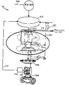
Referring to now to Fig. 6, a schematic block diagram illustrates the digital
field device 16 (of Fig. 3) which is a two-wire, loop-powered, two-way
digitally-
communicating positioner/valve combination. The digital field device 16
includes
a field device controller 102, an I/P transducer 104, a pneumatic relay 106,
an
actuator 108, and a valve 109, which are interconnected by various pneumatic
and
electrical lines.
The field device 16 receives operating signals and transmits status
information and data in digital form via the two-wire bus segment 34b,
preferably
according to the Fieldbus standard, and is, therefore, a two-wire positioner.
Similarly, the field device 16 receives power, primarily for driving the
device
controller 102 and the I/P transducer 104, via the two-wire continuous loop
bus
segment 34b and is, therefore, a loop-powered device.
As illustrated in Fig. 6, the I/P transducer 104 is electrically connected to
the device controller 102 by an I/P transducer control line 110 and, in the
illustrated embodiment, communicates with the device controller 102 using
analog
control signals.
The I!P transducer 104 generates a pneumatic signal that causes actuation
of the valve 109 and is highly useful in electromechanical devices for
converting
electrical signals to air pressure for a pneumatic positioner. The actuator
108
controls the position of a valve member 114 (which may be a valve stem) of the
valve 109 while a position sensor 116 senses the position of the valve member
114
and generates a feedback signal that is communicated to the device controller
102
-29-
CA 02492656 1997-10-O1
via a signal line 117. This position signal may be used by the device
controller
102 to control the operation of the field device 16 so that the I/P transducer
104
drives the pneumatic pressure in a manner that causes the valve member 114 to
be
at a desired position. Position and other feedback information may be stored
in a
storage unit or a memory of the device controller 102 and externally accessed
via
the bus 34.
As is standard, the field device 16 receives a supply of pressurized air from
an external source (not shown) via a pneumatic line 118 connected to the I/P
transducer 104 and to the pneumatic relay 106. An input sensor 120 typically
positioned between the external air source and the I/P transducer 104 measures
the
input pneumatic supply pressure in the pneumatic line 118 and delivers this
measurement to the device controller 102. The I/P transducer 104 is connected
to
the pneumatic relay 106 via a pneumatic control line 122 and an I/P sensor 124
is
positioned between the I/P transducer 104 and the pneumatic relay 106 to
measure
the pneumatic supply pressure in the line 122. Likewise, the pneumatic relay
106
is connected to the actuator 108 via a pneumatic actuation line 126 and a
relay
sensor 128 is positioned between the pneumatic relay 106 and the actuator 108
to
measure the pneumatic supply pressure in the line 126. The pneumatic lines
118,
122 and 126 are considered parts of a single pneumatic line interconnecting
the
transducer 104 and the valve 109.
During operation, the device controller 102 controls actuation of the valve
109 by controlling the I/P transducer 104 to set a controlled valve operating
pressure in the pneumatic control line 126. The device controller 102 sends a
control signal to the I/P transducer 104 via the I/P transducer control line
110 to
control an output pressure of the IlP transducer 104 and relay 106 combination
to
be between about 3-100 psi (0.21-7.06 kscm) which is applied to a control
input of
the actuator 108. The actuator 108 generates an output pressure that is
applied to
operate the valve 109.
Thus, as is known, the I/P transducer 104 converts electrical signals into a
pneumatic air pressure signal. One example of a suitable I/P transducer 104 is
-30-
CA 02492656 1997-10-O1
described in U.S. Patent No. 5,439,021, entitled "Electro-Pneumatic
Converter,"
issued to B.H. Burlage et al, on August 8, 1995. Likewise, the pneumatic relay
106, which serves as a pneumatic amplifier, is controlled by the I/P
transducer
104 as directed by the device controller 102 to increase the air pressure of
the
pneumatic actuation signal line 126 a controlled amount. Thus, generally
speaking, the pneumatic relay 106 supplies a controlled output pressure to a
loan
or utilization device, such as an actuator or a piston, in response to a
control
signal from the device controller 102. A suitable relay is described in U.S.
Patent
No. 4,974,625 entitled "Four Mode Pneumatic Relay," issued to S.B. Paullus et
al, on December 4, 1990. In the illustrated embodiment, the relay 106 is a
multi-
functional four-mode pneumatic relay that is configurable for any combination
of
direct/snap, direct/proportional, reverse/snap, or reverse/proportional
operation.
In the proportional mode, the pneumatic relay 106 develops a pressure output
that
is proportional to a pressure or force input. In an on/off or snap mode, the
pneumatic relay 10-6 generates a constant pressure output, usually equal to
the
pressure of the applied supply, in response to the application of a defined
range of
force or pressure control inputs. In a direct mode of operation, the output
pressure of the pneumatic relay 106 increases with an increasing input signal.
In
a reverse mode of operation, the relay output pressure decreases with an
increasing input signal.
The input sensor 120, the I/P sensor 124, and the relay sensor 128 are
pressure transducers that contain a pressure-to-electrical signal converter
for
converting a pressure signal to an electrical signal and supply feedback
signals to
the device controller 102 via a line 130. The I/P sensor 124 is diagnostically
useful for detecting failure of either the I/P transducer 104 or the pneumatic
relay
106 and determining, for example, whether a failure is a mechanical failure or
an
electrical failure. The I/P sensor 124 is also useful for detecting some
system
problems including a determination of whether the air pressure input to the
digital
field device 16 is sufficient. As a result, the I/P sensor 124 allows the
status of
-31 -
CA 02492656 1997-10-O1
the I/P transducer 104 and the pneumatic relay 106 to be rapidly diagnosed so
that
these devices can be replaced quickly, if necessary.
In one embodiment, a suitable valve 109 for use in the digital field device
16 is a valve and actuator assembly using a spring and diaphragm actuator on a
sliding stem valve which is used in an analog device described in U.S. Patent
No.
4,976,144, entitled "Diagnostic Apparatus and Method for Fluid Control Valves,
"
issued to W.V. Fitzgerald, on December 11, 1990. In this exemplary embodiment,
a
pressure signal of about 3 psi (0.21 kscm) is provided to the actuator 108 in
response to
an approximate 4 mA signal applied by the device controller 102 to the I/P
transducer
104, resulting in a corresponding pressure in the pneumatic actuation signal
line
126 that is insufficient to move the valve 109 from a fully opened position.
If the
field device controller 102 changes the control current applied to the I/P
transducer 104 to approximately 20 mA, the I/P transducer 104 generates a
pressure in the pneumatic actuation line 126 of approximately 15 psi (1.06
kscm),
which forces the valve 109 to a fully closed position. Various positions of
the
valve 109 between the fully opened position and the fully closed position are
attained through the operation of the device controller 102 controlling the
input
current applied to the IIP transducer 104 in the range from 4 mA to 20 mA.
The device controller 102 performs relatively high-speed digital
communications to receive control signals and to transmit position and
pressure
information to an external processor or workstation in the process control
network
10 via the bus 34. The device controller 102 includes storage or memory for
storing the results of multiple diagnostic tests so that pertinent data are
available
for analysis. Diagnostic operations, such as device diagnostics, are generally
in
the form of software program codes and are typically encoded, stored and
executed in the device controller 102 of the field device 16 in combination
with
program codes executing in an external device such as a processor or the host
workstation 12.
-32-
CA 02492656 1997-10-O1
A device diagnostic evaluation of the valve 109 may be performed through
the operation of the device controller 102 controlling the input current
applied to
the I/P transducer 104 in a range sufficient to test the valve 109 between
fully
opened and fully closed positions. During the device diagnostic evaluation,
the
outputs of the input sensor 120, the I/P sensor i24, and the relay sensor 128
are
monitored by the device controller 102 to sense the pneumatic pressure in the
pneumatic lines 118, 122 and 126, respectively, which are used for analysis.
The
output of the position sensor 116 is also monitored to detect position or
movement
of the valve stem 114 which corresponds to a position of or motion of a valve
plug
(not shown) within the valve 109.
Thus, a test operating cycle of the valve 109 is performed under control of
the device controller 102 by applying a controlled variable current to the IIP
transducer 104, sensing the pressure within the pneumatic lines 118, 122 and
126
and sensing the position of the valve stem 114 using the position sensor 116.
In
this manner, the device controller 102 simultaneously receives time-varying
electrical signals indicating the pressures at the illustrative locations and
the
position of the valve 109 and may used these signals to determine any number
of
device diagnostic parameters in any known or desired manner.
Conventional field devices typically do not include a position sensor, such
as the sensor 116, and do not use position sensor results for diagnostic
evaluations.
Also, conventional field devices do not include sensors such as the input
sensor
120, the I/P sensor 124, and the relay sensor 128 for measuring pressure in
the
pneumatic control and for converting the pressure signal to an electrical
signal to
facilitate diagnostic evaluation. However, these sensors and, particularly,
the I/P
sensor 124, improve diagnostic capabilities by facilitating localization of
failure,
error or fault conditions in the field device 16. In particular, the I/P
sensor 124
assists in differentiation between failures of the valve 109, other failures
in the
field device 16, and failures external to the field device 16 including
failures of
pneumatic line feeding the field device 16. The I/P sensor 124 is also useful
for
performing a diagnostic test to determine the operational status of the I!P
-33-
CA 02492656 1997-10-O1
transducer 104, the pneumatic relay 106, the field device 16 and the process
control system 10 in general. In one embodiment, the I/P transducer 104 and
the
pneumatic relay I06 are tested using a diagnostic test procedure that drives
the I/P
transducer 104 full open to measure the full air pressure provided to the
valve
109. While the I/P transducer I04 is driven open, the I/P sensor 124
constantly
measures pressure in the pneumatic control line 122. If the pressure begins to
decrease, the test indicates that the air supply may be insufficient. A
further
diagnostic test of air supply sufficiency is performed by pumping, the valve
109 by
applying an oscillating signal to the I/P transducer 104 so that the valve 109
begins a suction action with respect to the air supply and then measuring
maximum flow and maximum pressure values using the IIP sensor 124.
As illustrated in Fig. 7, the device controller 102 includes a microprocessor
140, an interface 142, a bus isolation circuit 144, a plurality of storage
devices
such as a random access memory (RAM) 146, a read-only memory (ROM) 148
and a nonvolatile random-access memory (NVRAM) 150, and a plurality of signal
processing devices such as an AID converter 152, a D/A converter 154 and a
multiplexer 156. The interface 142 (which is a bus connector) is a circuit
that
performs serial to parallel protocol conversion and parallel to serial
protocol
conversion and is used to add framing information to data packets according to
any
desired protocol definition, such as the Fieldbus protocol. The bus isolation
circuit 144 is a circuit that is used to convert a two-wire media
communication
signal on the bus 34 to a digital representation of the communication signal
and
supplies power received from the bus 34 to other circuits in the device
controller
102 as well as to the I/P transducer 104. The bus isolation circuit 144 may
also
perform wave-shaping and signaling on the bus 34.
The AID converter 152 is connected to transducers such as the position and
pressure transducers of the position sensor 116 and the pressure sensors 120,
124
and 128 of Fig. 6 as well as to any other desired analog input devices.
Although
the AID converter 152 may have a limited number of input channels, the
multiplexer 156 may be used to allow multiple signals to be sampled. If
desired,
-34-
CA 02492656 1997-10-O1
the multiplexer 156 may include a bank of amplifiers connected between the
signal
lines 117 and 130 (Fig. 6) to amplify the position, pressure and other
feedback
signals delivered thereto. The D/A converter 154 performs digital to analog
conversion on signals developed by the microprocessor I40 to be delivered to
analog components, such as the I/P transducer 104.
In a typical diagnostic test application, the controller 102 generates a 0-30
mA output test signal to the I/P transducer 104 in, for example, a programmed
ramp, step change, on/off form (or in any other desired manner) to operate the
valve 109 over a predetermined range of pneumatic pressures, and receives
diagnostic test output signals developed by the pressure input sensor 120, the
I/P
sensor 124, the relay sensor 128 and the position sensor 116. Specific test
procedures may be specified at and are generally initiated externally to the
field
device 16 using an input/output device such as a workstation, although the
procedures (and necessary information associated therewith) may also be input
directly to the controller 102 using an input device such as a keyboard. If
desired,
however, the test procedures may be stored in the controller I02. Similarly,
diagnostic test result information collected by or produced in the field
device
controller 102 is typically transferred to an external input/output device,
although
such information may also be directly displayed from the device controller 102
using, for example, a CRT display or a printer.
The field device 16 performs diagnostic test operations, such as device and
process diagnostics, using a program language interpreter embedded within the
controller 102 that interprets commands such as those requesting the
performance
of diagnostic process steps. The language interpreter is preferably
implemented in
a program code stored in the PROM 148 and executes in the microprocessor 140.
In some embodiments, a test (diagnostic) definition or procedure is encoded
into
the PROM 148 and, thus, preloaded into the field device 16. In other
embodiments, a test (diagnostic) definition or procedure is downloaded at or
before the time that the procedure is to be run and is stored in, for example,
the
RAM 146 for execution by the microprocessor 140. In a typical embodiment,
-35-
CA 02492656 1997-10-O1
r
some diagnostic functions are hard-coded into the PROM 148 and other functions
are downloaded, allowing the design and implementation of new diagnostic tests
without modifying the permanent or hard-coded software in the device 16.
Although the language interpreter is described within the context of the
S performance of process diagnostics or device diagnostics in a Fieldbus-type
device
(such as a Fieldbus valve), the language interpreter may be implemented in any
type of embedded controller, thereby enabling the use of common diagnostic
test
operations in any other type of embedded controller.
During operation, the field device 16 receives instructions via the bus 34
from an operator console or host workstation 12 in the process control network
10. The language interpreter executing in the device controller 102 interprets
the
instructions and executes the operations defined by the instructions. In an
illustrated embodiment, the language definition is depicted in a User
Interface
Command Table shown in TABLE 1, as follows:
-36-
CA 02492656 1997-10-O1
TABLE 1
Command Parameters)
Move Absolute Position
Move Relative Offset
Pause Time
Set Increment Increment
Increment UP
Increment Down
Loop Start Number of Iterations
Loop End
Stop
Data Rate Integer Multiple of Servo
Rate
//Comment Line
Label:
1~ Call Subroutine Subroutine Name
Return
Test Variable Variable, Value, Address
In this diagnostic language specification, a user can use a command name
to specify the command for execution. A comment line is any line that begins
with two slashes (//), according to the standard C/C++ convention. A label is
any word followed by a colon.
A diagnostic test procedure may be defined in an operator console such as
in the host 12 which generates a sequence of instructions in accordance with
the
language definition designed to implement the diagnostic test procedure. The
operator console then transmits the sequence of instructions encoded in the
interpretive language via the bus 34 to the digital field device 16 using, for
example, asynchronous communications in the Fieldbus protocol. The language
interpreter executing in the device controller 102 stores the received
instructions
-37-
CA 02492656 1997-10-O1
and interprets the instructions sequentially to control the valve 109 as
directed by
the instructions to thereby preform the diagnostic test. Diagnostic test
procedures
may, for example, control the field device 16 to repeatedly step the valve
109,
move the valve 109 up or down, move the valve 109 a selected amount in a
selected direction, and the like. The diagnostic test procedure also controls
the
collection of data from sensors in the field device 16 (as well as from other
devices) and controls transmission of data to the control console or host
workstation 12 via the bus 34. Of course, if desired, the diagnostic test
procedures implemented by instructions provided to the controller 102 may also
process the received data to determine diagnostic results and may send these
results to the host 12 or to other display device.
Thus, the diagnostic language interpreter within the device controller 102
controls operation of the field device 16 according to programmed instructions
to
enable diagnostic test procedures to be defined external to the digital field
device
16 so that diagnostic tests may be defined and modified freely without
modification of the field device 16. Likewise, new diagnostic control
procedures
may be developed and sent to the field device 16 after the field device 16 has
been
installed in the process control network 10. If desired, however, the device
16
may also or alternatively implement device and/or process diagnostic test
instructions stored in the device at the time of manufacture or at some other
time.
A control console (such as the host 12) typically includes diagnostic
development tools such as language editors and simulators for developing the
control routines in the diagnostic language for execution by the field device
16.
The control console also typically includes analysis tools for analyzing data
received from the field device 16 via the bus 34.
For the sake of completeness, example diagnostic program codes in an
interpretive language are illustrated as follows for controlling the valve
109:
-38-
CA 02492656 1997-10-O1
Program Code
~1) SAMA Static Test Definition
//CYCLE 0 TO 100% 3 TIMES
Dataltate 1
S CYCLE:Loop 3
MoveAbsolute 0.0
Pause 10000
Move Absolute 100.0
Pause 10000
LoopEnd
//MOVE TO 50% STEP UP 4 TIMES
Move Absolute 50.0
Pause 10000
SetIncrement 10.0
UP:LOOP 4
Increment Up
Pause 10000
LoopEnd
//STEP DOWN 8 TIMES
DOWN:Loop 8
IncrementDown
Pause 10000
LoopEnd
//STEP UP 4 TIMES
UP2:Loop 4
IncrementUp
Pause 10000
LoopEnd
Stop
~2) Step Change Test Definition
Dataltate 1
MoveAbsolute 50.0
Pause 10000
MoveAbsolute 60.0
Pause 10000
Stop
(3) Ste_pned Ramp Test Definition
DataRate 1
MoveAbsolute 50.0
-39-
'~ CA 02492656 1997-10-O1
Setlncrement 0.5
//STEP UP BY 0.5 FOR 10 TIMES
UP 1: Loop 10
IncrementUP
Pause 1000
LoopEnd
//STEP DOWN BY 0.5 FOR 10 TIMES
DOWNl: Loop 10
IncrementDown
Pause 1000
LoopEnd
SetIncrement 1.0
//STEP UP BY 0.5 FOR 10 TIMES
UP2: Loop 10
IncrementUp
Pause 1000
LoopEnd
//STEP DOWN BY 0.5 FOR 10 TIMES
DOWN2: Loop 10
IncrementDown
Pause 1000
LoopEnd
SetIncrement 2.0
//STEP UP BY 0. S FOR 10 TIMES
UP3: Loop 10
IncrementUp
Pause 1000
LoopEnd
//STEP DOWN BY 0.5 FOR 10 TIMES
DOWN3: Loop 10
IncrementDown
Pause 1000
LoopEnd
Stop
(41 Std Study Test Definition
DataRate 1
//STEP UP, DOWN, DOWN, UP, THEN INCREMENT STEP SIZE AND
//REPEAT UNTIL CHANGES DETECTED.
SetIncrement 0.5
IncrementUp
Pause 100
IncrementDown
Pause 100
-40-
CA 02492656 1997-10-O1
~,~
IncrementDown
Pause 100
Increment Up
Pause 100
SetIncrement 1.0
IncrementUp
Pause 100
IncrementDown
Pause 100
IncrementDown
Pause 100
IncrementUp
Pause 100
SetIncrement 2.0
IncrementUp
Pause 100
IncrementDown
Pause 100
IncrementDown
Pause 100
IncrementUp
Pause 100
SetIncrement 5.0
IncrementUp
2S Pause 100
IncrementDown
Pause 100
IncrernentDown -
Pause 100
IncrementUp
Pause 100
Stop
The first above-identified test (1) cycles three times, performs four steps
from the half open position, steps down eight times and steps up four times.
The
second test (2) performs a step change from 50 to 60 percent of the absolute
position of the valve. The third test (3) performs three cycles of a stepped
ramping waveform starting at SO percent of the absolute position of the valve.
The fourth test (4) repeats a series of steps with increasing magnitudes until
a
change in the valve is detected.
-41 -
CA 02492656 1997-10-O1
In these routines, the field device controller 102 implements a Conditional
pause to stop recording and sets a bit in a storage location to indicate where
a test
is stopped. The field device controller 102 also implements a Branch/GOTO
statement, a Loop forever statement, and a forced stop when an out-of service
flag
S is set. The pauses are synchronized with servo run times to that the test
does not
get out of synch with the valve.
The illustrative program code depicts only some examples of the types of
diagnostic tests that may be executed by the field device 16, there being many
other diagnostic tests that may be performed by program instructions provided
to
the field device 16 including, for example, a static cycle test in which the
valve
109 is moved 10 % up, 10 % down, 10 % up, 10 % down, and so on for a plurality
of cycles. Likewise, any device diagnostic measurements may be made including,
for example, simple measurements of valve travel or pressures within the
device
16 as developed by the sensors 116, 120, I24 and 128 and/or any desired
parameters derived from these or other measurements including, for example,
(1)
a dynamic error band, which is a plot of travel (e.g., the output of the
position
sensor 116) versus input (e.g., the control signal delivered to the controller
102),
(2) a plot of the drive signal (which is the output of the controller 102 as
delivered
to the IlP transducer 104) versus a pressure measurement, (3) a plot of drive
signal versus input signal, (4) output signal, which is plot of travel versus
drive
signal, (5) valve signature, which is plot of pressure versus travel, etc. Of
course
the pressure signals specified in these tests may be any desired pressure
signals,
such as those measured by any of the sensors 120, ,124 and/or 128.
Although the diagnostic language and diagnostic language interpreter is
advantageously implemented in a process control network 10 using Fieldbus
communications for communicating to a digital field device 16 in the form of a
two-wire, loop-powered, two-way digitally-communicating positioner, the
language
interpreter may be implemented in other embodiments. For example, the
diagnostic language interpreter may be implemented in any embedded controller
that communicates using any desired communication technology such as digital,
- 42 -
CA 02492656 1997-10-O1
analog, optical and the like. Furthermore, although the illustrated diagnostic
language interpreter communicates according to the Fieldbus standard protocol,
alternative embodiments of the diagnostic language interpreter may be
implemented in an embedded controller that communicates using other
communication protocols including, for example, the HART, Profibus, etc.
protocol and in systems that uses other than two-wire buses, such as systems
that
use four-wire buses. Likewise, the diagnostic language interpreter may be
implemented and used in other types of valves including, for example,
electronic
and hydraulic valves, as well as in other types of devices besides valve
devices.
Moreover, although the diagnostic language and diagnostic language
interpreter are described as defining a particular instruction set, other
instruction
sets may be implemented according to the specifications of the embedded
controller within which the language and interpreter are defined.
Of course, both device and process diagnostic tests may be performed by
issuing a command requesting one or more specific diagnostic test procedures
at
an operator console such as the host workstation 12. In the illustrated
embodiment, the diagnostic test procedures are implemented in two software
program codes. A first code executes in a processor external to the field
device
16, for example, in the host workstation 12, to create or initiate a
diagnostic test
and to receive collected data and perform analysis thereon, while a second
code
executes in the device controller 102 to implement a diagnostic test stored
therein
or provided by the host 12 in the form of program instructions. In contrast,
diagnostics in a conventional control system network are performed solely by
software executing in a processor of a control console. Many advantages are
gained by executing diagnostic tests at the field device level rather than at
a
control console level. For example, diagnostic testing may be performed in
parallel and may be distributed among many field devices by executing these
tests
at the device level. Likewise, a more accurate test may be performed in
process
control networks having distributed control functions, such as in the Fieldbus
protocol, where a host may not be able to deterministically control operation
of the
- 43 -
CA 02492656 1997-10-O1
field device due to the' fact that the host must communicate with the field
device in
an asynchronous manner to perform a diagnostic test.
Impleraentation of the two-way digital-communication defined by the
Fieldbus protocol is highly advantageous for improving the speed of
diagnostics,
both thnnugh an increase in data throughput and by facilitating parallel
performance of diagnostics among a plurality of field devices. Using the
Fieldbus
protocol, regularly scheduled messages are transferred at preseheduled times
and
unscheduled messages, including diagnostic messages and data, calibration
information and other information such as status indications, are transferred
when
the messages or data are ready attd the field device bus 34 is not otherwise
busy.
Diagnostic request messages are received by target field devices and
diagnostic
tests are performed by the field devices asynchronously with respect to
opezations
of other field devices_ When a diagnostic test operation is complete, a field
device
returns a response, such as result data, when the field device bus 34 is
available.
Accordingly, as noted above, a plurality of field devices may perform
diagnostic
te~Sts in parallel.
Referring now to Fig. 8, a flow chart 200 illustrates a technique for
performing diagnostic tests within the field device 16. At a step 202, the
field
device 16 receives a request to perform a sequence of instructions
implementing
one or more diagnostic tests. Of course, the host worlCStation 12 may issue
such
requests to any one or to a multiplicity of field devices simultaneously and
allow
each Field device to collect diagnostic data in parallel. If a multiplicity of
field
devnces are performnng tests simultaneously, the workstation 12 may collect
data
over an extended time interval as rapidly as the diagnostic tests are
perfotrned and
the results are made available on the bus 34 by the individual field devices.
Conventional devices using a unique set of wires to communicate with each
field
device only access a single field device at one time and only perform a single
test
for the single field device at one time.
At a step 204, the field device 16 performs a series of instructions to
implement the one or more diagnostic tests as directed by the request. Of
course,
-44-
CA 02492656 1997-10-O1
as noted above, the instructions may be stored in the memory of the field
device
16 or may be provided to the field device by the host I2 via, for example,
asynchronous communications. While the test is being implemented, one or more
parameters such as valve travel, pressure, etc. are measured in parallel.
Thus,
S while conventional field devices typically receive a command for a single
diagnostic test measurement, perform the measurement serially, and respond to
the
request with a single measurement value due to the limited communication
bandwidth and the lack of storage capability in these field devices, the field
device
16 may receive a request for a plurality of tests using a flexible test
protocol, may
perform the plurality of tests, and then respond with the results collected
during
the tests.
At a step 206, the field device 16 stores parametric results of the plurality
of tests measured for each of the diagnostic tests in a memory and, at a step
208,
transmits the data to the external requesting device. Two-wire, two-way
digital
communication in accordance with the Fieldbus standard substantially improves
the
test result throughput of the digital field device 16. In fact, digital
communications using Fieldbus protocol improves data transmission time by
approximately thirty times over HART systems so that, when the Fieldbus
protocol is used to perform diagnostic tests on multiple field devices in
parallel,
the amount of diagnostic test time for a process control network including
many
field devices is greatly reduced.
While conventional field devices typically have a separate pair of wires
connecting each field device to a network so that each field device has
exclusive
access to the wires, in the illustrated embodiment, results of the diagnostic
tests
are transmitted to the operator console or the host workstation 12 over the
bus 34
using the Fieldbus standard protocol which reduces the amount of wire required
to
communicate with the host 12.
As will be understood, during a diagnostic test procedure, the
microprocessor 140 controls the D/A converter 154 to supply a varying control
signal to the I/P transducer 104. For each particular control signal value and
- 45
CA 02492656 1997-10-O1
sample time, the microprocessor 104 directs the A/D converter 152 to measure
the
pressure and/or position related electrical signals developed by the sensors
116,
120, 124 and 128 (as well as any other signals from other sensors). As the
microprocessor 104 directs the field device controller 102 through an
operating
measurement cycle, pressure and valve travel information are accessed by the
device controller 102 and are processed or stored. The collected data is often
temporarily stored in the RAM 146 and is communicated to an external device,
such as a host workstation 12, often for subsequent processing, analysis and
display. Of course, the microprocessor 140 may also perform analysis if
desired.
For example, pressure information measured by the relay sensor 128 and
position information measured by the position sensor 116 may be analyzed in
combination to determine the change in valve diaphragm pressure as a function
of
valve position. Similarly, pressures measured by the input sensor 120, the I/P
sensor 124 and the relay sensor 128 may each be analyzed in combination with
the
position measured by the position sensor 116 to generate a deviation cycle
showing
a complete analysis of the operation of the valve 109 including
characteristics of
linearity, hysteresis and range.
Referring to Fig. 9, a flow chart 300 illustrates a diagnostic test protocol
implemented in the field device 16 to perform a diagnostic test. An operator
generates a sequence of diagnostic instructions at an operator console such as
the
workstation 12 and transmits the diagnostic instructions to the field device
16
which stores these instructions in memory. Alternatively, or in addition,
diagnostic instructions may be stored in the memory of the field device 16
during
manufacture of the device.
At a step 302, the field device 16 receives a diagnostic command via the
field device bus 34. If desired, the diagnostic command may be in the form of
instructions in an interpretive diagnostic language encoded for execution in
the
field device controller 102 or may be an instruction to initiate instructions
already
stored within the device 16. The device controller 102 executes the various
instructions to cause control elements in the digital field device 16 such as
the I/P
-46-
CA 02492656 1997-10-O1
transducer 104 and the actuator 108 to manipulate the valve 109 and to cause
sensors such as the input sensor 120, the I/P sensor 124, the relay sensor 128
and
the position sensor 116 to perform measurements. The control instructions may
also include instructions for processing the measurements and formatting data
for
presentation to a user. Additional instructions may cause the field device
controller 102 to send processed or formatted data to the requester via the
field
device bus 34.
At a step 304, the digital field device 16, upon request, performs a test
procedure in which, for example, the valve 109 is exercised from a full-closed
status to full-open, then back to a full-closed status. Likewise, the digital
field
device 16 may, upon request, perform a plurality of step tests including, for
example, a single step movement and analysis, and a ten-step movement and
response measurement. A stepped ramp test may be also be used and involves a
series of steps from a slight opening to a large opening of the valve, such as
a
ramp ranging from 10 % to 90 % in steps of, for example, 10 % increments. A
stepped study involves opening the valve in predefined steps, such as 1 %, 2%,
5
and 10%, moving the valve in a first direction a specified step size,
stabilizing,
and then moving the valve in a second direction at the specified step size.
At a step 306, the physical configuration of a diagnostic test is set by
commands communicated to the digital field device 16. The physical
configuration variables include a drive signal applied to the actuator 108, a
pressure setting applied to the I/P transducer 104, as well as actuator
pressure and
a valve travel reading. The physical configuration variables may be set as
independent test variables in some diagnostic tests and monitored as dependent
parameters in other tests.
At a step 308, the field device 16 measures predetermined parameters for a
particular physical test configuration. For many diagnostic tests, multiple
parameters are measured for a single test configuration. Typical parameters
that
are measured using a single test configuration include valve position, process
variable, actuator air pressure, supply pressure, drive signal, transducer set
point
- 47 -
..,_~
CA 02492656 1997-10-O1
and I!P air pressure, to allow determination of, for example, valve signature,
output signal, dynamic error band, drive versus pressure, and travel versus
input
signal amplitude.
At a step 310, the field device 16, through the operation of the device
controller 102, stores the multiple parameters for a single test configuration
in, for
example, the RAM 146: At a step 312, the data is communicated to the host 12
or other device. If testing is to be performed using a different diagnostic
test
configuration, the field device 16, through the operation of the device
controller
102 in a conditional step 314, loops back to the step 306 to modify the test
configuration.
The diagnostic tests in the illustrated field device 16 are substantially
improved in comparison to convention field devices in part through
improvements
in the diagnostic protocol structure, in part through improvements in
communication, and in part through the implementation of additional sensors in
the
field device 16. The improvements in diagnostic protocol structure enable the
field device 16 to measure multiple parameters far a single test
configuration. The
distribution of diagnostic control operations to the field devices enable
diagnostic
tests to be completely controlled, upon request, within a field device so that
multiple requests may be made to multiple field devices with the individual
field
devices controlling the diagnostic tests independently and in parallel to one
another. The improvements in diagnostic protocol structure also advantageously
enable the test procedures to be modified external to the field device by
programming changes. Accordingly, new diagnostic capabilities may be added
and wholesale changes in diagnostic operations may be made without modifying
the field device. Modification of a field device is highly disadvantageous due
to
the tremendous expense of shutting down a process line. The improvements in
communication enable the field device 16 to measure multiple parameters for a
single test configuration. Conventional field devices receive a request on
communication lines that are dedicated to a specific field device, set a test
configuration according to the specifications of the request, and return a
single test
-48-
CA 02492656 1997-10-O1
measurement according to the request. A subsequent measurement under the same
test configuration is made by repeating the step, including the redundant step
of
setting the test configuration. The improved communications of the illustrated
field device 16 advantageously allow diagnostic testing of multiple devices in
parallel, increasing diagnostic test throughput. Furthermore, the improved
digital
communications provide for a plurality of data types where analog
communications
(of conventional field devices) do not.
While the invention has been described with reference to various
embodiments, it will be understood that these embodiments are illustrative and
that
the scope of the invention is not limited to them. Many variations,
modifications,
additions and improvements of the embodiments described are possible. For
example, the field device 16 is but one illustration of a suitable control
valve and
actuator combination. Other suitable valve types include sliding stem, rotary
plug,
rotary ball, butterfly, eccentric disk valves as well as other known valve
types.
Other suitable actuators include spring and diaphragm, spring and piston,
double-
acting piston, hydraulic, electrohydraulic, electric or other known actuator
types
using either a rotary or sliding stem valve. Thus, the field device 16 is
merely
illustrative of various types of positioners or other devices for controlling
an
actuator and valve to modulate power. Moreover, the field device in which the
diagnostics of the present invention are used or located can be a device other
than
a valve including, for example, a pump controller, a variable speed drive,
etc.
Still further, the field device 16 is not limited to operation in compliance
with the
Fieldbus standard but is further applicable to other digital communication
standards including HART, WORLDFIP, LONWORKS, Profibus and the like.
Of course, device and process diagnostic tests may be stored in the
controller 102 in the form of function blocks or other software and may be
made
so that these diagnostic tests are accessible by the public using any host
device,
such as a personal computer, so that these tests may implemented without
requiring much knowledge on the part of the user. In one embodiment, one or
more easily accessible diagnostic routines are stored in the device (e. g. ,
the device
-49-
,
,~ ~ CA 02492656 1997-10-O1
16) and may be run by issuing a single command from a host specifying which
test
is to be run. All of the data necessary for the test is stored in the device
and all
output data collected for the test is sent to the host after the test is
complete.
Generally speaking, such "public" device and process diagnostics can be
commanded to write to transducer blocks to effect movement of, for example,
valve components, and to read and store data produced by the sensors using a
trending block in the Fieldbus protocol. Because all of information required
by
the host is located in the device description of the field device, no
proprietary
knowledge is required to implement any of these public diagnostics. With the
use
of such public diagnostics, the operation of a field device may be compared
with
the operation of any other field device made by other manufacturers having the
same diagnostics therein.
Example waveforms used in such public diagnostics are illustrated in Figs.
l0A-lOC. As indicated by Fig. 10A, a public diagnostic may cause the valve I09
to move in a step-wise romping manner in the opening direction at individual
steps
of, for example, one percent for a particular number of steps (e.g., five
steps) and
is then moved in a step-wise romping manner in the closing direction at
individual
steps of one percent until the initial value or position of the valve has been
reached. Preferably, a step to the new set point is instantaneous, i.e., no
rate
limits are in effect, and the delay time at each new set point is fixed and is
determined by the size and response characteristics of the valveJactuator
device.
Alternatively, as indicated by Fig. 10B, a public diagnostic may move a valve
through a ramp of five percent in the opening direction and then immediately
move the valve through a ramp of five percent in the closing direction. The
rate
of the ramps are preferably fixed and set to a rate determined by the
valve/actuator
size. Most preferably, the ramp rate is approximately one-half of the maximum
rate of the speed for the device. Moreover, as indicated by Fig. 10C, a public
diagnostic may move a valve in the opening (or closing) direction in a single,
for
example, five percent step from the current valve position, with the
instantaneous
step time set that so that no rate limits are in effect. This test concludes
with the
-50-
CA 02492656 1997-10-O1
valve in a new valve baseline position five percent above (or below) the
initial
point.
To implement the public diagnostics illustrated in Figs. l0A-lOC using the
Fieldbus protocol, the host 12 sends an execution command to the device
storing
the public diagnostics which sets a trend list in the device (e.g., the
device; 16) and
then sets an appropriate VCR in the device 16 for trending. Next, the link
object
of the device 16 is set for trending and, thereafter, the diagnostic test
proceeds.
At this time, the host may display a message to the user indicating that the
diagnostics are in process and the host may read the status or progress of the
diagnostics to determine if an error condition occurs. After the device 16 has
completed the diagnostic, the host reads and stores the trended data and turns
the
trending off. The host may then perform analysis on the retrieved data. If a
status of, for example, 200% or more is received from the device 16, an error
in
the diagnostics has occurred and the host may indicate such an error to the
user.
After analyzing the received data, the host may display the diagnostic data
developed from the stored trends or any results determined therefrom to the
user.
For example, the host 12 may graphically depict the actual movement of the
valve
in response to one or all of the above-described public diagnostic waveforms
along
with the input waveform to depict the response of the device 16 to the
waveform.
When performing a public, or other diagnostic, the device 16 first
determines if a diagnostic command signal has been received and, if so,
verifies
that the transducer block of the device is operating satisfactorily. If so,
the device
16 then sets updated pointers for trend data to indicate which data should be
stored
in the trend block and verifies that a sufficient set point range is available
to
perform the diagnostic. For example, to run a test that requires five percent
movement of the valve in the opening direction, the valve must be at or below
95
percent of its maximum movement. If this range is not available, the device 16
may send back an error message to the host 12.
If no error has occurred, the device 16 runs a selected test using test times
and slope rates determined from a lookup table (based on the valve/actuator
size)
-51 -
CA 02492656 1997-10-O1
stored in. the device 16 amt takes the desired measurements such as the
position of
the valve. During the ,test, the valve updates the test status with a percent
complete from 0-100 percent and, if an error is detected, writes an error code
gmater than 200 percent to a diagnostic status variable which is read by-the
host
12. At the end of the test, assurtiing no errors have been reached, the
diagnostic
test writes a 100 percent status in the diagnostic test status variable and,
thereafter,
reports collected trend data to the host using normal stack operations set
up'to do ,
the trending according to standard Fieldbus protocols. Preferably, the loop
speed
of the diagnostic test is set to be relatively high as compared to the changes
within
the input waveform so that enough trend data is collected to adequately model
the
response of the device 16 to the diagnostic waveform. Thus, in a Fieldbus
protocol, where the firequency of data samplilag in a trend object is tied to
the
execution rate of the function blocks, the loop execution rate should be much
higher than the rate of changes within the input waveform to enable the trend
15. object to collect enough data to observe the response of the device 16 to
the input
waveform after each significant change therein.
Of co~n~e, the public diagnostics illus:raLed in, for example, Fig. 10, are
best suited to perform device diagnostics, in that they can be advantageously
used
to cause a particular device to go through one or more diagnostic steps or
operations during which time the outputs of transducers within the device are
measured to determine characteristics of that device. When used in a Fieldbus
protocol far device diagnostics, these tests do not require the use of any
additional
function blocks but, instead, can be run by an individual device controller
(such as
the controller 102 of Fig. 6) to control the transducer blocks apart from the
normal operation associated with the func4on blocks operating w ithin the
device.
Of course, if desired, a function block may be used to analyze the collected
data in
some manner and to provide the analyzed data to the host.
Referring now to Fig. 11A, a process control loop 4U0 capable of
implementing device or process diagnostics locally from a device in a FieIdbus
process control network is illustrated in detail. The loop 400 includes the
control
-52-
CA 02492656 1997-10-O1
loop, LOOP1 of Fig. 4, having the AI function block 66 of the device 20
communicatively connected via the bus 34 with the PID function block 64 and
the
A/O function block 63 both of the device 16. The loop 400 also includes a data
collection function block 401 configured to receive data from the AO function
block 63, the Ai function block 66 and, if desired, other function blocks such
as
AI function blocks 402 and 404, which may be located in other field devices
connected within the process control network 10. Of course, the function
blocks
66, 402 and 404 are configured to communicate with the data collection
function
block 401 using standard synchronous communications, such as
publisherlsubscriber communications defined within the Fieldbus protocol.
During operation, the controller 102 within the field device 16 interrupts
the normal operation of the loop formed by the function blocks 66, 64 and 63
and
delivers a diagnostic waveform to the input of the AO function block 63. At
that
time, the AO function block 63 has its status mode changed to, for example, a
local control mode, which cascades back to the PID function block 64 causing
the
PID function block 64 to shed its mode status to, for example, manual, which
in
turn prevents the PID function block 64 from producing an output signal based
on
the inputs received thereby. As noted above, the diagnostic waveform may be
stored in the controller 102 of the device 16 or may be provided by the host
12
prior to implementation of the diagnostic test. Of course, the waveform or
other
instructions cause the valve associated with the device 16 to go through a
series of
movements associated with a device or' a process diagnostic test.
During a device diagnostic, the data collection function block 401 receives
data from the AO function block 63 as well as data from other transducers
within
the device 16, such as transducers associated with position sensors and/or any
of
the pressure sensors Like those illustrated in Fig. 6. During a process
diagnostic,
the data collection function block 401 also or alternatively receives data
related to
process variables as developed by the AI function blocks 66, 402, 404, as well
as
any other function blocks within the process control network 10. The data
collection function block 401 may collect this data along with data pertaining
to
-53-
~ ~ CA 02492656 1997-10-O1
the timing and the magnitude of the diagnostic waveform delivered to the AO
function block 63 and may store this data for future delivexy to the host 12,
where
it may be processed and illustrated to a user.
After the device or process diagnostic test is completed, the data collected
by the function block 401 is delivered to the host 12 and the controller 102
releases control of the AO function block 63 back to the P1D function block 64
to
return the loop comprising the blocks 66, 64 and 63 to W onnal operation. Of
course, at this time, the status mode of the blocks 64 and 63 axe returned to
norn~al operation.
1O It should be noted that, while the data collection function block 401 does
not necessarily require any scheduled synchronous execution time, the
communication interconnections of the function block 401 must be established
when configuring the process control loop 400 and, therefom, these
communication interconnections exist even when no diagnostic is naming. In
other words, wlten the data collection function block 401 needs to have data
published to it osier the bus 34, it must be configured to receive that data
(i.e., the
data published by other devices) at the initialization of the process control
network
10 to avoid requiring a user to reconf gore the network IO simply to perform .
diagnostics. However, as noted above, because the data collection function
block
401 will generally collect only process variable data that is already
published on
the bus 34 or will collect data generated internally within the device in
which the
data collection function block 401 is present, the operation of the data
collection
function block 401 w~l not generally add to the amount of synchronous
communications on the bus 34 or require additional scheduled execution times
for
the process contxoi network 10. If desired, however, the data collection
function
block 401 may be configured to receive data not usually published on the bus,
which requires that the publishing block be configured to publish that data at
the
start up of the process control network 10.
Referring now to Fig. 11B, a process control loop 406 capable of
implementing local diagnostics within a device in a Fieldbus process control
_54_
j CA 02492656 1997-10-O1
network is illustrated in detail. Similar to the loop 400 of Fig. 11A, the
loop 406
includes the control loop, LOOP1 of Fig. 4, having the AI function block 66 of
the device 20 communicatively connected via the bus 34 with the PID function
block 64 and the A/O function block 63 both of the device 16. The loop 406
also
includes a data collection function block 408 (located in the device 16) which
operates essentially the same as the data collection function block 401 except
that
it is configured only to receive data locally from, for example, the AO
function
block 63, the PID function block 64 or any other transducers or sensors within
the
device, such as pressor sensors, position sensors, etc. The data collection
function
block 408 is especially useful in performing device diagnostics where the
required
data is generated locally within a device. Because, the block 408 does not
need to
receive data from the bus 34, it does not have to be configured initially at
the
start-up of the process control network.
Of course, the data collection function blocks 401 and 408 are only two
ways of collecting diagnostic data within a process control device, there
being
many other methods of collecting such data in different types of process
control
networks and devices. For example, the data for a device or a process may be
collected by other parasitic software located in a device that does not
conform to
the definition of a fieldbus function block.
Referring now to Fig. 12, a flowchart 500 illustrates steps performed by a
typical process diagnostic using, for example, the loop 400 of Fig. 11. At a
step
502, a data collection setup is provided to the data collection function block
401
and other data necessary for a diagnostic test is delivered from a host (e.g.,
host
12) to the device 16 in which the diagnostic is to be executed. Thereafter,
the
diagnostic is initialized by a user to cause the loop being tested to be
isolated from
the rest of the process control network. Upon initialization, the device 16
changes
the status of the AO function block 63 to, for example, a local control mode,
which causes the PID function block 64 (or other upstream function blocks) to
change mode automatically according to Fieldbus control standards. Thereafter,
a
block S06 performs a diagnostic instruction stored within the memory of the
-55-
CA 02492656 1997-10-O1
device 16 and the data collection function block 401 collects diagnostic and
process data at the block 508. A block 510 determines if the test is complete
and,
if not, returns control to the block 506 which performs the next diagnostic
instruction. Of course, the next instruction may be a repeat of the previous
one
causing, for example, a device to move in single direction until a limit has
been
reached.
The loop performed by the blocks 506, 508 and 510 repeats until the test is
complete or until some error has occurred or is detected at the block 510, at
which
time a block 512 ends the diagnostic test and a block 514 restores normal
operating status to, for example, the AO function block 63 which causes the
PID
function block 64 to again change its status and control the AO function block
63
according to normal control operation.
The data collected by the data collection function block 401 is provided to
the host 12 which analyses and/or displays the data. If desired, analysis can
be
performed in the device 16 and the results of the analysis may be provided by
the
host 12 to a display unit for display.
Using the device diagnostic method according to the present invention, the
device 16 collects both device and process data without requiring separate
control
by a host to implement or receive the data. Because the diagnostic is
performed
within a device and is controlled by the controller of that device instead of
a
separate host device, the timing of the test can be controlled precisely and
data
collected during a diagnostic test can be easily time aligned with the
operation
performed by the device to provide accurate correspondence between the test
waveforrn and the results of the test. When implemented to perform a process
diagnostic, the data collection function block 401 of the loop 400 (or any
similar
loop having a data collection function block configured to collect data from
one or
more process control loops) can be used to target loop performance rather than
just device performance and can be used to indicate whether or not a valve is
appropriate for a loop or if there are other issues with the loop that would
limit its
overall performance. Process and/or device testing may be implemented
-56-
s ~ CA 02492656 1997-10-O1
periodically without requiring a process to be shutdown or placed in a non-
operating state. Of course, when the data collection function block 401 is
configured to collect only data already published on the loop, it is limited
by the
control schedule as to the data that can be collected and used for
diagnostics.
Although the diagnostic functions have been described herein as performing
diagnostics on or using a downstream AO function block 63 (which is an output
function block), and as receiving inputs from and delivering feedback to an
upstream PID function block 64 (which is a control function block) connected
in a
simple control loop configuration, the data collection function block 401 or
other
diagnostic function routine of the present invention can be used in
conjunction with
other output functions or function blocks and other control functions or
function
blocks as desired and can be implemented in control loops having
configurations
other than that illustrated in Fig. 11.
Moreover, while some of the diagnostics described herein have been
implemented in the form of a Fieldbus "function block, " it is noted that the
diagnostics of the present invention can be implemented using other types of
blocks, programs, hardware, firmware, etc., associated with other types of
control
systems and/or communication protocols. In fact, while the Fieldbus protocol
uses
the term "function block" to describe a particular type of entity capable of
performing a process control function, it is noted that the term function
block as
used herein is not so limited and includes any sort of device, program,
routine, or
other entity capable of performing a process control function in any manner at
distributed locations within a process control network. Thus, the diagnostic
function blocks described and claimed herein can be implemented in other
process
control networks or using other process control communication protocols or
schemes (that may now exist or that may be developed in the future) which do
not
use what the Fieldbus protocol strictly identifies as a "function block. "
Still further, while process and device diagnostics have been described
herein as being used in performing diagnostics on (or using) positioner/valve
devices, it is noted that these diagnostics can be performed on (ar using)
other
-57-
t ~ CA 02492656 1997-10-O1
types of devices, such as those having moveable elements like dampers, fans,
etc.
Likewise, although the diagnostics described herein are preferably implemented
in
software stored in a process control device, they may alternatively or
additionally
be implemented in hardware, firmware, etc., as desired. If implemented in
software, the diagnostics of the present invention may be stored in any
computer
readable memory such as on a magnetic disk, a laser disk, or other storage
medium, in a RAM, ROM, EPROM, etc. of a computer, and the like. Likewise,
this software may be delivered to a user or a device via any known or desired
delivery method including, for example, over a communication channel such as a
telephone line, the Internet, etc.
Thus, while the present invention has been described with reference to
specific examples, which are intended to be ihustrative only and not to be
limiting
of the invention, it will be apparent to those of ordinary skill in the art
that
changes, additions or deletions may be made to the disclosed embodiments
without
departing from the spirit and scope of the invention.
_ 58