Sélection de la langue

Search

Sommaire du brevet 2493110 

Énoncé de désistement de responsabilité concernant l'information provenant de tiers

Une partie des informations de ce site Web a été fournie par des sources externes. Le gouvernement du Canada n'assume aucune responsabilité concernant la précision, l'actualité ou la fiabilité des informations fournies par les sources externes. Les utilisateurs qui désirent employer cette information devraient consulter directement la source des informations. Le contenu fourni par les sources externes n'est pas assujetti aux exigences sur les langues officielles, la protection des renseignements personnels et l'accessibilité.

Disponibilité de l'Abrégé et des Revendications

L'apparition de différences dans le texte et l'image des Revendications et de l'Abrégé dépend du moment auquel le document est publié. Les textes des Revendications et de l'Abrégé sont affichés :

  • lorsque la demande peut être examinée par le public;
  • lorsque le brevet est émis (délivrance).
(12) Brevet: (11) CA 2493110
(54) Titre français: PIECE DE COIN DE HAUTEUR REGLABLE
(54) Titre anglais: ADJUSTABLE HEIGHT CORNER FITTING
Statut: Périmé et au-delà du délai pour l’annulation
Données bibliographiques
(51) Classification internationale des brevets (CIB):
  • B65D 90/12 (2006.01)
  • B60P 07/13 (2006.01)
(72) Inventeurs :
  • BRENNAN, JAMES F., JR. (Etats-Unis d'Amérique)
(73) Titulaires :
  • JAMES F., JR. BRENNAN
(71) Demandeurs :
  • JAMES F., JR. BRENNAN (Etats-Unis d'Amérique)
(74) Agent: BORDEN LADNER GERVAIS LLP
(74) Co-agent:
(45) Délivré: 2008-09-30
(86) Date de dépôt PCT: 2003-07-18
(87) Mise à la disponibilité du public: 2004-01-29
Requête d'examen: 2005-01-20
Licence disponible: S.O.
Cédé au domaine public: S.O.
(25) Langue des documents déposés: Anglais

Traité de coopération en matière de brevets (PCT): Oui
(86) Numéro de la demande PCT: PCT/US2003/022379
(87) Numéro de publication internationale PCT: US2003022379
(85) Entrée nationale: 2005-01-20

(30) Données de priorité de la demande:
Numéro de la demande Pays / territoire Date
10/201,330 (Etats-Unis d'Amérique) 2002-07-23

Abrégés

Abrégé français

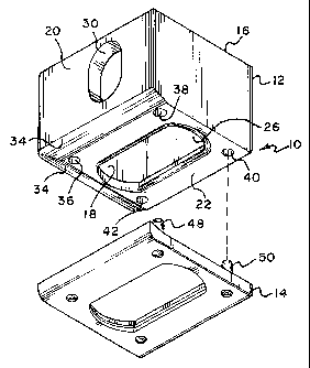
Cette invention se rapporte à une pièce de coin de hauteur réglable (10) pour conteneurs d'expédition, qui est constituée par un bloc de forme rectangulaire essentiellement creux (12) comportant une paroi inférieure (22), des parois terminales (20) et des parois latérales (18). Une ouverture allongée (26) est ménagée dans la paroi inférieure (22) et est destinée à coopérer avec un mécanisme de blocage servant à bloquer le conteneur d'expédition sur la plate-forme d'un véhicule. Est également prévue une plaque de forme essentiellement rectangulaire (14) qui est complémentaire de la paroi inférieure (22) et qui est destinée à être fixée temporairement à cette paroi, pour augmenter la hauteur du bloc. Dans cette plaque (14) est également ménagée une ouverture allongée (44) qui est complémentaire de l'ouverture (26) ménagée dans la paroi inférieure (22). Lorsque la plaque (14) est fixée, les ouvertures (44,26) de la plaque (14) et de la paroi inférieure (22) sont alignées. Toutefois, la plaque (14) amène la pièce de coin (10) à se prolonger vers le bas sur un demi-pouce environ sous le conteneur pour une expédition par camion, bateau ou wagon de chemin de fer. Lorsque la plaque (14) est retirée, le plancher de la pièce de coin (10) est essentiellement à fleur avec le plancher du conteneur, ce qui permet de transporter le conteneur par avion cargo.


Abrégé anglais


An adjustable height corner fitting (10) for a shipping container is comprised
of a substantially hollow rectangularly shaped block (12) having a bottom wall
(22), end walls (20) and side walls (18). An elongated aperture (26) is
located in the bottom wall (22) and is adapted to cooperate with a locking
mechanism in order to lock the shipping container to the platform of a
vehicle. Also provided is a substantially rectangularly shaped plate (14) that
is complementary to the bottom wall (22) and is adapted to be temporarily
attached thereto in order to increase the height of the block. The plate (14)
also has an elongated aperture (44) therein which is complementary to the
aperture (26) in the bottom wall (22). When the plate (14) is attached, the
apertures (44,26) in the plate (14) and in the bottom wall (22) are in
alignment, but the plate (14) causes the corner fitting (10) to extend
downwardly approximately a half an inch below the container for shipment on a
truck, boat or rail car. With the plate (14) removed, the bottom of the corner
fitting (10) is essentially flush with the bottom of the container thereby
allowing the container to be transported by cargo plane.

Revendications

Note : Les revendications sont présentées dans la langue officielle dans laquelle elles ont été soumises.


8
Claims
1. An improved corner fitting for a shipping container comprising:
a hollow rectangular block having a bottom wall, at least one end wall and
at least one side wall;
an elongated aperture located in said bottom wall adapted to cooperate
with a locking mechanism in order to lock said shipping container to a
platform
of a vehicle, and
a substantially rectangularly shaped plate complementary to said bottom
wall and adapted to be attached thereto in order to increase the height of
said
block, said plate having a single elongated aperture therein complementary to
said aperture in said bottom wall, said apertures being in alignment with each
other when said plate is attached to said bottom wall, and means for
temporarily
attaching said plate to said bottom wall of said block.
2. The improved corner fitting as claimed in Claim 1 wherein said means for
temporarily attaching said plate to said bottom wall of said block includes
said
plate having a plurality of vertically extending projections and said bottom
wall
having a plurality of complementary holes adapted to receive said projections.
3. The improved corner fitting as claimed in Claim 2 wherein said projections
are in the form of upstanding pins.
4. The improved corner fitting as claimed in Claim 3 further including means
for temporarily preventing said pins from being removed from said holes when
said plate is properly positioned on said bottom wall.
5. The improved corner fitting as claimed in Claim 1 wherein said bottom
wall and said end wall intersect each other and include a chamfered area at
the
intersection.

9
6. The improved corner fitting as claimed in Claim 5 wherein said plate has
an upper surface and includes a portion that is complementary to and is
adapted
to mate with said chamfered area of said bottom wall.
7. The improved corner fitting as claimed in Claim 5 wherein said bottom
wall and said side wall intersect each other and include a chamfered area at
the
intersection.
8. The improved corner fitting as claimed in Claim 7 wherein said plate
includes portions that are complementary to and are adapted to mate with both
of said chamfered areas of said bottom wall.
9. An improved corner fitting for a shipping container comprising:
a hollow rectangular block having a bottom wall, at least one end wall and
at least one side wall;
an elongated aperture located in said bottom wall adapted to cooperate
with a locking mechanism in order to lock said shipping container to a
platform
of a vehicle, and
a substantially rectangularly shaped plate complementary to said bottom
wall and adapted to be attached thereto in order to increase the height of
said
block, said plate having an elongated aperture therein complementary to said
aperture in said bottom wall, said apertures being in alignment with each
other
when said plate is attached to said bottom wall, and means for temporarily
attaching said plate to said bottom wall of said block, said attaching means
including said plate having a plurality of vertically extending projections
and said
bottom wall having a plurality of complementary holes adapted to receive said
projections.
10. The improved corner fitting as claimed in Claim 9 wherein said projections
are in the form of upstanding pins.

10
11. The improved corner fitting as claimed in Claim 10 further including
means for temporarily preventing said pins from being removed from said holes
when said plate is properly positioned on said bottom wall.
12. An improved corner fitting for a shipping container comprising:
a hollow rectangular block having a bottom wall, at least one end wall and
at least one side wall, said bottom wall and said end wall intersecting each
other
and including a chamfered area at the intersection;
an elongated aperture located in said bottom wall adapted to cooperate
with a locking mechanism in order to lock said shipping container to a
platform
of a vehicle, and
a substantially rectangularly shaped plate complementary to said bottom
wall and adapted to be attached thereto in order to increase the height of
said
block, said plate having an elongated aperture therein complementary to said
aperture in said bottom wall, said apertures being in alignment with each
other
when said plate is attached to said bottom wall, and means for temporarily
attaching said plate to said bottom wall of said block.
13. The improved corner fitting as claimed in Claim 12 wherein said plate has
an upper surface and includes a portion that is complementary to and is
adapted
to mate with said chamfered area of said bottom wall.
14. The improved corner fitting as claimed in Claim 12 wherein said bottom
wall and said side wall intersect each other and include a chamfered area at
the
intersection.
15. The improved corner fitting as claimed in Claim 14 wherein said plate
includes portions that are complementary to and are adapted to mate with both
of said chamfered areas of said bottom wall.

Description

Note : Les descriptions sont présentées dans la langue officielle dans laquelle elles ont été soumises.


CA 02493110 2005-O1-20
WO 2004/009453 PCT/US2003/022379
1
Description
ADJUSTABLE HEIGHT CORNER FITTING
s Technical Field
The present invention is directed toward an improved corner fitting
and, more particularly, to such an improved corner fitting that allows the
height
of the same to be adjusted so as to be useful for a variety of purposes.
io
Background Art
In order to utilize various modes of transportation, shipping
containers typically use a system of standard corner fittings that allows them
to
is be safely affixed to their support platform. For a shipping container to be
carried
by truck, rail or ship it must comply with I.S.O. Standards promulgated by the
International Standards Organization. Typically the shipping containers are
affixed by means of'a quick lock mechanism which secures the shipping
container to the support platform at the lower four corner fittings. These
four
2o points are located on the lower planar surface of the container at the
respective
ends of the container. The fitting is a cube embedded, usually affixed by
welding, in each corner of the container with three sides exposed to the
exterior
of the container.
The average fitting is hollow and has a hole in each of the three
2s sides to receive a fastener for attaching the container to a support
platform,
which may be part of a vehicle such as a truck chassis, a train flatbed or the
deck or hold of a ship. The holes in the fitting are typically shaped like an
oval
with two flat sides thus having a long axis and a short axis.
A commonly used fastener for securing the container is described,
3o for example, in U.S. Patent No. 2,963,310 to Abolins. Abolins shows a twist-
lock
type locking system that has a head shaped complementary to the hole in the
fitting. The head is attached to the end of a narrow neck that is rotatably
affixed

CA 02493110 2005-O1-20
WO 2004/009453 PCT/US2003/022379
2
to the support platform. The head is inserted into the fitting hole and then
the
neck is rotated. This twists the head so that ifs long dimension overlaps the
short
axis of the hole, thereby preventing it from being removed and securing it to
the
fitting.
By regulation, the bottom plane of each of the lower corner fittings
extends downwardly approximately a half an inch below the lower surface of the
bottom of the main portion of the shipping container. As a result, when one
container is stacked on top of another, the lower corner fittings of the top
io container rest on and are supported by the upper corner fittings of the
bottom
container. This prevents the main body portions of the containers from
contacting each other which could cause damage to them.
Shipping containers with conventional corner fittings as described
above have been successfully used for many years on ships, rail cars, trucks
is and the like. Similar shipping containers have also been used on aircraft.
Conventional corner fittings, however, have created a problem in such
applications.
Most aircraft used for transporting shipping containers utilize a
series of rollers that allow the container to be rolled into and out of the
cargo
2o hold of the plane. To function properly, this roller system requires that
the
bottom of the container be substantially flat or at least have no protrusions
extending downwardly therefrom. Downward protrusions can interfere with or
damage the roller system of the aircraft. As a result conventional shipping
containers with corner fittings that extend downwardly even a half an inch can
2s not be used. Rather, special shipping containers must be utilized or
conventional
shipping containers must first be lifted onto an aircraft pallet which has a
substantially flat bottom surface.
This, of course, creates a problem when it is desired to use the
same shipping container with a cargo plane and some other form of
3o transportation. That is, a shipping container being brought to a plane by
firuck

CA 02493110 2005-O1-20
WO 2004/009453 PCT/US2003/022379
cannot be rolled directly onto the plane. Similarly, a container rolled off of
a
plane cannot be placed directly onto a truck as the corner fittings do not
extend
downwardly as required. In both cases, the goods or equipment within the
container must be transferred into a different container to accommodate the
different form of transportation. To Applicant's knowledge, there is no
shipping
container currently available that can be properly and directly used with a
cargo
plane and with other forms of transportation.
1o Disclosure of the Invention
The present invention is designed to overcome the deficiencies of
the prior art discussed above. It is an object of this invention to provide a
corner
fitting that is secured to a shipping container and which can easily and
quickly be
~s modified to allow the container to be transported by cargo plane or any
other
conventional form of transportation.
It is another object of the invention to provide a corner fitting which
can easily and quickly be modified to allow the container to be transported by
cargo plane or any other conventional form of transportation and which
complies
2o the I.S.O. standards set forth by the International Standards Organisation.
It is a further object of this invention to provide a corner fitting that
can easily be modified to either extend a half inch or so below the lower
surface
of the container or to be essentially flush with the lower surface:
1n accordance with the illustrative embodiments, demonstrating
2s features and advantages of the present invention, there is provided an
improved
adjustable height corner fitting for a shipping container. The fitting is
comprised
of a substantially hollow rectangularly shaped block having a bottom wall, end
walls and side walls. An elongated aperture is located in the bottom wall and
is
adapted to cooperate with a locking mechanism in order to lock the shipping
3o container to the platform of a vehicle. Also provided is a substantially
rectangularly shaped plate that is complementary to the bottom wall and is
adapted to be temporarily attached thereto in order to increase the height of
the

CA 02493110 2005-O1-20
WO 2004/009453 PCT/US2003/022379
4
block. The plate also has an elongated aperture therein which is complementary
to the aperture in the bottom wall. When the plate is attached, the apertures
in
the plate and in the bottom wall are in alignment, but the plate causes the
corner
fitting to extend downwardly approximately a half an inch below the container
for
shipment on a truck, ship or rail car. With the plate removed, the bottom of
the
corner fitting is essentially flush with the bottom of the container thereby
allowing
the container to be transported by cargo plane.
Other objects, features and advantages of the invention will be
readily apparent from the following detailed description of a preferred
embodiment thereof taken in conjunction with the drawings.
Brief Description of the Drawings
is For the purpose of illustrating the invention, there is shown in the
accompanying drawings one form which is presently preferred; it being
understood that the invention is not intended to be limited to the precise
arrangements and instrumentalities shown.
Figure 1 is a side elevational view of a shipping container using the
2o corner fitting of the present invention arranged to be used for shipping on
a
truck, ship, rail car or the like;
Figure 2 is a view similar to Figure 1 with the corner fitting of the
present invention arranged to be used for shipping on a cargo plane;
Figure 3 is a perspective cut away view of the corner fitting
2s secured to a shipping container;
Figure 4 is an exploded view of a corner fitting of the present
invention illustrating the details thereof, and
Figure 5 is a top perspective view of the bottom plate that forms a
part of the corner fitting of the invention.

CA 02493110 2005-O1-20
WO 2004/009453 PCT/US2003/022379
Best Mode for Carryina Out the Invention
Referring now to the drawings in detail wherein like reference
numerals have been used throughout the various figures to designate like
elements, there is shown in Figure 4 a corner fitting constructed in
accordance
with the principles of the present invention and designated generally as 10.
The
corner fitting 10 is comprised essentially of two parts: a substantially
rectangularly shaped hollow block 12 and a bottom plate 14 that is removably
to secured thereto.
The block 12 is, in many ways, similar to a conventional corner
fitting in that it includes a top 16 (which may be open or closed), at least
one
side wall 18, at least one end wall 20 and a bottom wall 22. The block 12 is
permanently secured to the corner of a shipping container 24 as shown in
is Figures 1, 2 and 3 which is to be temporarily locked onto the platform of a
tractor
trailer, rail car or ship. As with conventional corner fittings known in the
art, an
elongated opening or aperture 26 is formed in the bottom wall 22 of the block
12
and circular or elongated openings 28 and 30 are formed in the side and end
walls 18 and 20, respectively.
2o As best shown in Figure 4, a chamfer area or rounded edge 32 is
formed between the area where the bottom wall 22 and end wall 20 intersect.
Similarly, a chamfered area 34 is formed at the intersection between the
bottom
wall 22 and the side wall 18. The bottom wall 22 also includes four holes 36,
38,
40 and 42 that pass through from the bottom exterior surface of the block 12
to
2s the interior thereof.
The bottom plate 14, as best shown in Figures 4 and 5, is also
substantially rectangularly shaped and is complementary to the bottom wall 22
of the block 12. An elongated aperture 44 is formed in the center of the plate
14
and is complementary to the aperture 26 formed in the bottom wall 22.
3o Extending upwardly from the top surface of the plate 14 are a plurality of
projections in the form of pins 46, 48, 50 and 52. Each of the pins is
complementary to and is adapted to pass through the respective openings 36,

CA 02493110 2005-O1-20
WO 2004/009453 PCT/US2003/022379
38, 40 and 42 formed in the bottom wall 22 of the block 12. One or more of the
pins may include spring loaded ball detents such as shown at 54 which will
help
to temporarily attach and hold the plate 14 in position at the bottom of the
block
12 when desired.
As best shown in Figure 5, the plate 14 also includes raise
chamfered areas 56 and 58 that are complementary to the areas 32 and 34 on
the bottom surface of the block 22. That is, the upper surface of the plate 14
is
essentially complementary to the lower surface of the block 12.
io The plate 14 is temporarily attached to the block 12 by simply
pushing the plate into place with the pins 46, 48, 50 and 52 passing through
the
openings 36, 38, 40 and 42. The detent balls 54 will hold the plate in place
and
the aperture 44 will be in direct alignment with the aperture 26. In this
configuration, the corner fitting 10 will resemble a conventional corner
fitting with
is the thickness of the plate 14 extending approximately one half inch below
the
bottom surface 60 of the container 24 as shown in Figures 1 and 3. The
shipping
container can then be used in any conventional manner as is well known in the
art.
When it is desired to load the shipping container 24 onto a cargo
2o plane where the downward projection of the corner fittings may create a
problem, all that is required is to remove the plate 14 from the block 12.
This is
accomplished by merely pulling the plate downwardly after the container has
been raised. If necessary, a workman can insert his hand through one of the
openings 28 or 30 or the apertures 44 and 26 to help push the pins downwardly
2s or to release the detent balls 54 if the same becomes stuck. With the plate
14
removed, the bottom wall 22 of the block 12 is essentially flush with the
bottom
60 of the container 24 as shown best in Figure 2. The chamfer 32 at the
leading
end of the container bottom helps to guide the container over the rollers in
the
floor of the cargo plane.
3o The plates 14 that have been removed from the bottom of the
blocks 12 can be shipped along with the shipping containers 24 on the cargo

CA 02493110 2005-O1-20
WO 2004/009453 PCT/US2003/022379
7
plane. When the containers are removed from the plane at the destination, the
plates 14 can then be reassembled onto the bottom and the shipping containers
can then be shipped on rail cars, trucks, ships or any other similar vehicles
in a
conventional manner.
The present invention may be embodied in other specific forms
without departing from the spirit or essential attributes thereof and
accordingly
reference should be made to the appended claims rather than to the foregoing
specification as indicating the scope of the invention.

Dessin représentatif
Une figure unique qui représente un dessin illustrant l'invention.
États administratifs

2024-08-01 : Dans le cadre de la transition vers les Brevets de nouvelle génération (BNG), la base de données sur les brevets canadiens (BDBC) contient désormais un Historique d'événement plus détaillé, qui reproduit le Journal des événements de notre nouvelle solution interne.

Veuillez noter que les événements débutant par « Inactive : » se réfèrent à des événements qui ne sont plus utilisés dans notre nouvelle solution interne.

Pour une meilleure compréhension de l'état de la demande ou brevet qui figure sur cette page, la rubrique Mise en garde , et les descriptions de Brevet , Historique d'événement , Taxes périodiques et Historique des paiements devraient être consultées.

Historique d'événement

Description Date
Le délai pour l'annulation est expiré 2017-07-18
Lettre envoyée 2016-07-18
Accordé par délivrance 2008-09-30
Inactive : Page couverture publiée 2008-09-29
Inactive : Taxe finale reçue 2008-06-20
Préoctroi 2008-06-20
Un avis d'acceptation est envoyé 2007-12-20
Lettre envoyée 2007-12-20
Un avis d'acceptation est envoyé 2007-12-20
Inactive : CIB enlevée 2007-12-19
Inactive : CIB en 1re position 2007-12-19
Inactive : CIB enlevée 2007-11-29
Inactive : CIB attribuée 2007-11-29
Inactive : CIB attribuée 2007-10-29
Inactive : CIB enlevée 2007-10-29
Inactive : Approuvée aux fins d'acceptation (AFA) 2007-08-30
Inactive : CIB de MCD 2006-03-12
Inactive : Page couverture publiée 2005-03-23
Inactive : Inventeur supprimé 2005-03-21
Lettre envoyée 2005-03-21
Inactive : Acc. récept. de l'entrée phase nat. - RE 2005-03-21
Demande reçue - PCT 2005-02-16
Exigences pour l'entrée dans la phase nationale - jugée conforme 2005-01-20
Exigences pour une requête d'examen - jugée conforme 2005-01-20
Déclaration du statut de petite entité jugée conforme 2005-01-20
Toutes les exigences pour l'examen - jugée conforme 2005-01-20
Exigences pour l'entrée dans la phase nationale - jugée conforme 2005-01-20
Demande publiée (accessible au public) 2004-01-29

Historique d'abandonnement

Il n'y a pas d'historique d'abandonnement

Taxes périodiques

Le dernier paiement a été reçu le 2008-06-20

Avis : Si le paiement en totalité n'a pas été reçu au plus tard à la date indiquée, une taxe supplémentaire peut être imposée, soit une des taxes suivantes :

  • taxe de rétablissement ;
  • taxe pour paiement en souffrance ; ou
  • taxe additionnelle pour le renversement d'une péremption réputée.

Les taxes sur les brevets sont ajustées au 1er janvier de chaque année. Les montants ci-dessus sont les montants actuels s'ils sont reçus au plus tard le 31 décembre de l'année en cours.
Veuillez vous référer à la page web des taxes sur les brevets de l'OPIC pour voir tous les montants actuels des taxes.

Historique des taxes

Type de taxes Anniversaire Échéance Date payée
Requête d'examen - petite 2005-01-20
Taxe nationale de base - petite 2005-01-20
TM (demande, 2e anniv.) - petite 02 2005-07-18 2005-06-17
TM (demande, 3e anniv.) - petite 03 2006-07-18 2006-06-20
TM (demande, 4e anniv.) - petite 04 2007-07-18 2007-06-26
Taxe finale - petite 2008-06-20
TM (demande, 5e anniv.) - générale 05 2008-07-18 2008-06-20
TM (brevet, 6e anniv.) - générale 2009-07-20 2009-06-23
TM (brevet, 7e anniv.) - générale 2010-07-19 2010-07-02
TM (brevet, 8e anniv.) - générale 2011-07-18 2011-06-27
TM (brevet, 9e anniv.) - générale 2012-07-18 2012-07-03
TM (brevet, 10e anniv.) - générale 2013-07-18 2013-07-05
TM (brevet, 11e anniv.) - générale 2014-07-18 2014-06-18
TM (brevet, 12e anniv.) - générale 2015-07-20 2015-06-19
Titulaires au dossier

Les titulaires actuels et antérieures au dossier sont affichés en ordre alphabétique.

Titulaires actuels au dossier
JAMES F., JR. BRENNAN
Titulaires antérieures au dossier
S.O.
Les propriétaires antérieurs qui ne figurent pas dans la liste des « Propriétaires au dossier » apparaîtront dans d'autres documents au dossier.
Documents

Pour visionner les fichiers sélectionnés, entrer le code reCAPTCHA :


Pour visualiser une image, cliquer sur un lien dans la colonne description du document. Pour télécharger l'image (les images), cliquer l'une ou plusieurs cases à cocher dans la première colonne et ensuite cliquer sur le bouton "Télécharger sélection en format PDF (archive Zip)" ou le bouton "Télécharger sélection (en un fichier PDF fusionné)".

Liste des documents de brevet publiés et non publiés sur la BDBC .

Si vous avez des difficultés à accéder au contenu, veuillez communiquer avec le Centre de services à la clientèle au 1-866-997-1936, ou envoyer un courriel au Centre de service à la clientèle de l'OPIC.


Description du
Document 
Date
(aaaa-mm-jj) 
Nombre de pages   Taille de l'image (Ko) 
Description 2005-01-19 7 315
Revendications 2005-01-19 3 142
Dessins 2005-01-19 2 66
Abrégé 2005-01-19 2 78
Dessin représentatif 2005-03-22 1 16
Accusé de réception de la requête d'examen 2005-03-20 1 178
Rappel de taxe de maintien due 2005-03-20 1 111
Avis d'entree dans la phase nationale 2005-03-20 1 202
Avis du commissaire - Demande jugée acceptable 2007-12-19 1 163
Avis concernant la taxe de maintien 2016-08-28 1 178
PCT 2005-01-19 9 361
Correspondance 2008-06-19 1 32