Note : Les descriptions sont présentées dans la langue officielle dans laquelle elles ont été soumises.
CA 02493654 2005-O1-19
1
TITLE
BARBEQUE GRILL LIGHT
TECHNICAL FIELD
The present invention relates generally to accessories for cooking device, and
more
particularly to an improved side light for gas barbeque grills.
BACKGROUND OF THE INVENTION
Barbeque gas grills are very popular for outdoor cooking. They generally
comprise a
cart, a firebox or cooking chamber, a cover for the firebox or cooking
chamber, one or more gas
burners, controls for the gas burners, one or more propane (e.g. gas)
cylinders, cooking grid, side
shelves with or without burners, and perhaps one or more warming racks.
Numerous models
exist in all types, styles, sizes and shapes. An example of such a typical
barbeque is shown in
U.S. Pat. No. D462,564. This patent shows at least two side tables, one of
which having a side
burner and grill.
Gas grills are generally used for outdoor barbecuing. Many of these grills are
of the
transportable type wherein the grill is attached to a support structure having
wheels and handles
for pushing the support structure or cart into a desired location.
Accordingly, the grill may be
used at night and in a location that is not provided with direct, task or
indirect lighting. Even if
indirect lighting is provided, it may be insufficient to allow for the person
using the gas grill to
be able to grill items to the desired level.
CA 02493654 2005-O1-19
2
Various devices have been proposed in the prior art for lighting a grill, such
as those
disclosed in U.S. Patent No. 3,992,618 to Matthews; U.S. Patent No. 5,257,169
to Walendziak;
U.S. Patent No. 5,664,875 to Hegedus; and U.S. Patent No. 6,202,640 to
Naperola.
As such, it is desired to have portable lighting which does not reduce the
ability of the
grill to be moved to a desired location. It is also desired to have a grill
lighting device that is
easily installed on new or existing gas grills. Furthermore, it is desirable
to have a lighting
apparatus v~~hich is directable so as to direct the light on to the grill
cooking grate or an area
adj acent to the grill.
SUMMARY OF THE INVENTION
An aspect of the present invention is a barbecue light comprising: (a) a base
having a C-
shaped socket with a slot; (b) a first arm having a first end with an opening
and a second end
being receivable in the slot and having a ball sized to be movably received in
the slot so as to
allow rotary motion of the second arm; (c) a second arm having a first and
second end, the first
slidably receivable in the opening of the first arm between an extended and a
retracted position;
and (d) an illuminating means pivotally attached to the second end of the
second arm, the
illuminating means is controlled by control means having an off position when
the illuminating
means is in a substantially horizontal position and an on position when the
illuminating means is
moved beyond the substantially horizontal position; whereby a user directs
light by any one of
pivoting the illuminating means, moving the second arm between the extended
and retracted
position, and rotating the second arm.
The barbeque light of the present invention is portable and can be easily
affixed to a side
table of gas grill so as to illuminate items cooking on a grate at night or
under low light
CA 02493654 2005-O1-19
3
conditions and to enable a person using the barbecue grill to see the items)
cooking. It can be
easily and rapidly attached to the side plate by a person having limited
technical ability without
the use of numerous tools.
BRIEF DESCRIPTION OF THE DRAWINGS
Various objects, features and attendant advantages of the present invention
will become
more fully appreciated and better understood when considered in conjunction
with the
accompanying drawings, in which like reference characters designate the same
or similar parts
throughout the several views.
Figure 1 is a front perspective view of a gas grill having an embodiment of
the present
invention;
Figure 2 is a front perspective view of an embodiment of the present
invention; and
Figures 3 to 5 are explodes view of a portion of Figure 1 showing embodiments
of the
present mvenhon.
DETAILED DESCRIPTION OF THE PREFERRED EMBODIMENT
In order that the invention may be more fully understood, it will now be
described, by
way of example, with reference to the accompanying drawings in which Figures 1
through 5
illustrate embodiments of the present invention.
In the description and drawings herein, and unless noted otherwise, the terms
"vertical"
and "horizontal", can be references to a Cartesian co-ordinate system in which
the vertical
direction generally extends in an "up and down" orientation from bottom to top
while the
CA 02493654 2005-O1-19
4
horizontal direction generally extends in a "left to right" or "side to side"
orientation. In
addition, the lateral direction generally extends in an orientation that is
extending out from or
into the page.
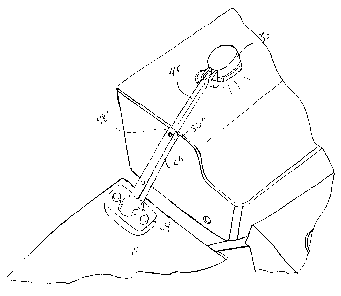
Refernng to Figure 1, one embodiment of the present invention is shown. Figure
1
S provides a gas barbeque 10 having a grill housing 12 designed to enclose a
burner (not shown).
A cooking surface or cooking grid, in the nature of one or more grill plates
(not shown), and a
warming rack (not shown) may also be contained within the grill housing 12.
Barbeque 10 also
has at least one side table 16 to which lighting assembly 18 is attached. A
fuel flow controller,
for instance console 15, may be provided to moderate the flow of fuel to the
burner. If a self
contained fuel source is used, including a fuel container, such as a propane
tank for example,
then a fuel source or container support base 20 may be employed to support the
tank. If an
external fuel source, such as piped natural gas, is used then base 22 may be
omitted. Relocation
of the barbeque 10 may be facilitated by the addition of wheels 24 and/or
casters 26.
In the context of describing embodiments of the claimed invention, variations
of detail
are disclosed. While one such variation is described in conjunction with
another particular
variation, yet other variations may generally be used in association as well.
The description
provided is therefore not intended to be limited to the particular combination
of variations
disclosed.
Lighting Element
Figure 2 provides a detailed view of lighting element 18 while Figures 3 to 5
provide an
exploded view of a portion of Figure 1. As shown in Figure 2 and Figure 3, for
example, side
table 16 has lighting element 18 removably attached thereto. As shown in
greater detail in
CA 02493654 2005-O1-19
Figure 2, there is provided light fixture or illumination means 30 pivotally
attached to extendable
arm 32 by way of joint 34. While joint 34 is shown as a type of joint allowing
light fixture 30 to
pivot or move through a single axis, it will be understood that any joint
(e.g. saddle joint, ball
and socket joint, etc.) may be suitable for attaching light fixture 30 to arm
32. Arm 32 is
5 movably attached to base 36 by way of joint 38. Base 36 can be removable
affixed to side table
16 by way of a pair of bolts 40a' and 40a" as well as nuts 41' and 41 a" which
are received in
appropriate size bores in side table 16. While nuts and bolts 40a', 40a", 41
a' and 41 a" are
disclosed, it will be understood that any suitable means for attaching or
affixing base 36 to side
table 16 could be employed. Base 36 could also be formed as part of side table
16 during
manufacture of the barbeque 10 and its constituent elements.
Light fixture 30 can be provided by any light that provides sufficient
illumination to
allow the user to see the items cooking. In the preferred embodiment, three
battery powered
light-emitting diode (LED) 30', 30" and 30"' are provided. Light fixture 30
consists of a circuit
which can include a "tilt switch", known in the art. Typically such "tilt
switches" are placed in
electronic devices to automatically turn the electronic device "on" and "off'
based on the
position of conductive material such as a sphere or ball. As such, tilt
switches can also be
referred to as "ball switches". A typical tilt switch comprises a hollow,
enclosed housing or
capsule having electrodes within the housing and extending through and outside
the housing.
Conventionally, a conductive material, such a ball is placed within the hollow
housing. The
housing is aligned in an "on" position when the conductive material in the
shape of a ball
electrically connects each of the electrodes, allowing the flow of
electricity. The housing is
aligned in an "off' position when the ball in the housing is tilted and does
not electrically
connect the electrodes, preventing the flow of electricity. It will be
understood that when
CA 02493654 2005-O1-19
6
lighting fix 30 is in a generally horizontal position, as shown in Figures 1
and 3, the tilt switch
will be in the "off' position and lights 30', 30", and 30"' wily not be lit.
Once lighting fixture
30 is moved out of the horizontal position, the tilt switch will be moved into
the "on" position
and lights 30', 30", and 30"' will become lit. For example, lighting fixture
30 could be moved
out of the horizontal position by as little as 25° to 30° from
the horizontal in order for the tilt
switch to move from the "off' position to the "on" position. It will be
understood that the degree
to which it is necessary to move lighting fixture 30 out of the horizontal in
order to activate LED
lights 30', 30" and 30"', can varying depending on the circumstances.
It will be understood that the light fixture 30 could also be placed in the
lid of the
barbeque or on the handle such that when the lid is lifted the lights will be
on and will be off
when the lid is returned to the initial closed position.
Once out of the horizontal position, it can be seen in Figures 2, 4 and 5 that
light fixture
30 can be movable along one axis by way of joint 34. Joint 34 provides
movement of light
fixture 30 along an axis generally parallel to a longitudinal axis of arm 32,
generally extending
from joint 38 along arm 32 towards light fixture 30. Additional range of
motion can be provided
by ball and socket joint 38 which generally permits some degree of rotary
motion possible in
every axis. Joint 38 consists essentially of a spherical knob or ball 40 at
one end of arm 32, with
the knob fitting securely into a mating socket 42 in base 36. Mating socket 42
is formed by
circular generally C shaped side wall 44. As can be seen in Figure 2, C-shaped
side wall 44 has
a slot or recess 46 provided therein. Slot 46 is sized to fit the portion of
arm 32 immediately
adjacent ball 40. This feature will be discussed in greater detail below. By
virtue of movement
about joints 34 and 38, it will be understood that light fixture 30 can be
placed in virtually any
angle as required by the user.
CA 02493654 2005-O1-19
7
In addition to movement along joints 34 and 38, arm 32 can telescope between a
retracted, shorter position and an extended, longer position, as seen in
Figure 5. As shown in
Figure 2, arm 32 can be comprised of upper portion 48 and lower portion 50.
Upper and inner
portion 48 of arm 32 is disposed within lower and outer portion 50 of arm 32
and is slidably
received therein. Outer potion 50 has a lower end terminating with ball 40 and
an upper end
generally disposed towards light fixture 30. Inner portion 48 has an upper end
terminating with
joint 34 attaching to lighting fixture 30 and a lower portion disposed at all
times within outer
portion outer 50 of arm 32 (not shown). Provided on a surface of inner portion
48 of arm 32 can
at least one spring loaded knob, 48' which is movable between an inward
position and an
outward position but can be biased outwardly. Provided on a surface of outer
portion 50 of arm
32 is at least two bores, 50' and 50", sized to received knob 48' of inner
portion 48, when knob
48' is in the outward position. The interaction of the knob and the bores
provide a locking
mechanism for the movement of inner portion 48 along the longiduntial axis of
arm 32 between
the extended position and the retracted position. When inner portion 48 is in
the shorter retracted
position (as shown in Figures 2 and 4), knob 48' will engage bore 50' thereby
preventing
movement of inner portion 48 of arm 32 along the longitutindal axis. However,
a user can
depress spring loaded knob 48', releasing knob 48' from bore 50' thus allowing
inner portion 48
to move from the shorter retracted position to the longer extended position.
When bore 50" and
knob 48' are parallel, knob 48' will be biased up and into bore 50" thereby
locking inner portion
48 in the longer extended position (See Figure 5). To release inner portion
48, knob 48' is
simply disengaged from bore 50' and inner position 48 is moved back to the
retracted shorter
position.
CA 02493654 2005-O1-19
8
In operation, light element 18 can be removably attached to side table 16 by
nuts and
bolts 40a' and 40a" as well as 41 a' and 41 a" (as shown in Figure 2). When
lighting is not
required light element 18 can be kept in the downward or horizontal position
(as shown in
Figures 1 and 3). In this position light 30 is not illumintated as the title
switch or ball switch
contained therein is in the "off' position. In such a position, it will be
seen in Figures l and 3
that the light 30 of lighting element 18 is directed away from the barbeque
10. As clearly shown
in Figures 4 and 5, base 36 is generally oriented towards barbeque 10 while
light 30 of the
lighting is generally oriented away from barbeque 10. In order for lighting
element 18 to be
oriented in the downward or horizontal position, C-shaped side wall 44 is
pointing away from
barbeque 10. In other words, the slot or recess 46 is provided on the side
which is not
immediately adjacent the grill housing (see figures 4 and 5). As shown in
Figures land 2, C-
shaped side wall 44 is provided in a reverse C configuration so that the
opening of the "C" points
away from barbeque such that the C would be reversed if it were read from left
to right, with the
barbeque being on the right and light 30 being on the left. Conversely, if
lighting element were
on the side table opposite side table 16, the other side of barbeque 10 as
shown in Fig. 1, the
opening of the "C" would point away from barbeque such that the C would be in
a normal
orientation if it were read from left to right, with the barbeque being on the
left and light 30
being on the right (not shown).
When the user of barbeque 10 required task lighting, however, such as when
items were
being cooked on grill plates 14, light element 18 can be lifted up by arm 32
from the downward
horizontal position towards a more vertical position. Once light 30 was lifted
sufficiently
vertical to move the conductive material into the "on" position, LED lights
30', 30" and 30"'
will be activated and provide the necessary illumination. By moving one or
both of joints 34 and
CA 02493654 2005-O1-19
9
38, light 30 can be positioned so as to provide maximum task lighting to the
area as dictated by
the user. In addition, should further positioning be required, outer portion
50 of arm 32 can be
moved from either the shortened or lengthened position to provide maximum
lightening.
Over time or with increased use, however, ball and socket joint 38 may loosen.
As such,
the ability of lighting element 18 to maintain a particular desired position
may decrease relative
to when the lighting element was first used or installed. In order to overcome
this, generally C-
shaped wall 44 will prevent arm 32 from moving to the horizontal position. As
shown in Figures
4 and S, arm 32 will rest on wall 44 so as to maintain light 30 over the
barbeque 10.
It is understood that while certain forms of this invention have been
illustrated and
described, it is not limited thereto except insofar as such limitations are
included in the following
claims and allowable functional equivalents thereof.