Note : Les descriptions sont présentées dans la langue officielle dans laquelle elles ont été soumises.
CA 02494547 2010-03-02
1
SELF ADJUSTING GROOVED PLIERS
TECHNICAL FIELD
This invention relates to hand tools.
More particularly, the present invention relates to
grooved pliers.
In a further and more specific aspect, the instant
invention concerns grooved pliers which are self adjusting.
BACKGROUND ART
Pliers having jaws which are adjustable between various
positions are well known in the art. Typically, these types
of pliers include two halves each having a jaw portion the
halves are coupled at a pivot by a bolt or rivet. One half
includes a channel allowing the pivot to be adjusted by
moving the bolt or rivet therealong for a wider or narrower
association between the jaw portions of the halves. The
conventional grooved pliers include a plurality of grooves
formed in one half proximate the channel for receiving a
tongue formed on the other half. The adjustment is
accomplished by opening the pliers fully so that the tongue
leaves the grooves, and sliding the two halves until the
tongue on one section aligns with the desired groove on the
other section. When the conventional pliers are closed a
slight amount, the tongue enters the groove and is locked
into that adjustment, preventing movement of the pivot in
the channel until the sections are fully opened again. This
adjustment requires the use of two hands, and careful
alignment of the tongue with the desired groove, or the
pliers will not close. More importantly, when in use if the
pliers are at the wrong adjustment, the pliers must be
removed and readjusted.
It would be highly advantageous, therefore, to remedy
the foregoing and other deficiencies inherent in the prior
art.
CA 02494547 2010-03-02
2
Accordingly, it is an object of the present invention
to provide new and improved adjustable grooved pliers.
It is another object of the present invention to
provide adjustable grooved pliers which are self adjusting.
Another object of the present invention is to provide
grooved pliers which can be adjusted with one hand.
Yet another object of the present invention is to
provide adjustable grooved pliers which can be adjusted
while engaging an object.
DISCLOSURE OF THE INVENTION
Briefly, to achieve the desired objects of the instant
invention in accordance with a preferred embodiment thereof,
provided are self adjusting grooved pliers include a first
section having a jaw portion and a channel formed
therethrough adjacent the jaw portion and a second section
having a jaw portion and a pivot extending therefrom. The
pivot is slidably received in the channel to allow wider or
narrower association between the jaw portion of the first
section and the jaw portion of the second section. The
pivot pivotally couples the first section to the second
section for movement between an open position and a gripping
position. A plurality of grooves is formed in the first
section and a tongue extends from the second section. The
tongue is received in one of the plurality of grooves,
locking the pivot in position within the channel only upon
the first section and the second section reaching the
gripping position. A biasing assembly acts on the pivot,
urging the pivot upward in the channel toward the jaw
portion of the first section.
In another aspect of the present invention, the biasing
assembly includes a coil spring fitted into a handle portion
of the first section and an extension member having an end
engaging the coil spring and an opposing end extending into
the channel and engaging the pivot. The coil spring and the
CA 02494547 2010-03-02
3
extension cooperate to urge the pivot in the channel toward
the first jaw portion.
In another aspect, the biasing assembly includes a post
extending from the pivot into a receptacle extending from
the first section and a coil spring carried by the post
within the receptacle. The compression spring is compressed
between the pivot and the receptacle.
In yet another aspect, the second jaw portion of the
second section is carried by a jaw element pivotally coupled
to the second section. The jaw element is movable between a
start position and a finish position, and is biased into the
start position by a biasing member.
BRIEF DESCRIPTION OF THE DRAWINGS
The foregoing and further and more specific objects and
advantages of the instant invention will become readily
apparent to those skilled in the art from the following
detailed description of a preferred embodiment thereof taken
in conjunction with the drawings, in which:
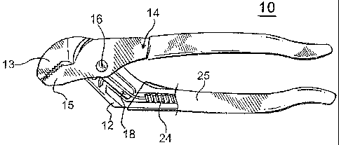
FIG. 1 is a plan view of self adjusting grooved pliers
according to the present invention;
FIG. 2 is a disassembled plan view of the pliers of
FIG. 1;
FIG. 3 is an enlarged view of the interaction of the
tongue and grooves of the pliers of FIGS. 1 and 2;
FIG. 4 is an enlarged perspective view of a portion of
the biasing mechanism;
FIG. 5 is a plan view of self adjusting grooved pliers
according to the present invention, illustrating another
embodiment of a biasing mechanism;
FIG. 6 is a plan view of self adjusting grooved pliers
according to the present invention, illustrating yet another
embodiment of a biasing mechanism;
CA 02494547 2010-03-02
4
FIG. 7 is a plan view of another embodiment of self
adjusting grooved pliers according to the present invention;
FIG. 8 is an enlarged exploded perspective view of a
section of the pliers of FIG. 7;
FIG. 9 is a plan view of the pliers of FIGS. 7 and 8 as
it appears in the adjusting orientation;
FIG. 10 is a plan view of the pliers of FIGS. 7 and 8
as it appears in the locked orientation;
FIG. 11 is a plan view of yet another embodiment of
self adjusting grooved pliers according to the present
invention;
FIG. 12 is a plan view of a section of the pliers of
FIG. 11 showing double tongues; and
FIG. 13 is a plan view of a section of the pliers of
FIG. 11 showing double grooves.
BEST MODES FOR CARRYING OUT THE INVENTION
Turning now to the drawings in which like reference
characters indicate corresponding elements throughout the
several views, attention is first directed to FIG. 1 which
illustrates self adjusting grooved pliers generally
designated 10. Pliers 10 are similar to conventional
grooved pliers with the exception that modifications have
been made to the grooves and tongues, as will be described
presently, and a biasing mechanism has been added, which
while advantageous, is not required. Pliers 10 include a
section 12 having a jaw portion 13 and a section 14 having a
jaw portion 15, coupled at a pivot 16. Section 12 includes
a channel 18 adjacent jaw portion 13, which receives pivot
16, allowing pivot 16 between sections 12 and 14, to be
adjusted for a wider or narrower association between jaw
portions 13 and 15. section 12 and section 14 pivot about
pivot 16 moving jaw portions 14 and 15 between an open
position and a gripping position.
CA 02494547 2010-03-02
Conventional grooved pliers include a plurality of
grooves formed in one section proximate the channel for
receiving a tongue formed on the other section. The
adjustment is accomplished by opening the pliers fully so
5 that the tongue leaves the grooves, and sliding the two
sections until the tongue on one section aligns with the
desired groove on the other section. When the conventional
pliers are closed a slight amount, the tongue enters the
groove and is locked into that adjustment, preventing
movement of the pivot in the channel until the sections are
fully opened again.
Pliers 10 of the present invention, includes grooves 20
formed in section 12 proximate channel 18 for receiving a
tongue 22 formed on section 14. Tongue 22 is shortened to a
tooth or nub when compared to existing grooved pliers
tongues. Additionally, the positioning of tongue 22 is such
that it enters one of grooves 20 slightly before or when
jaws 13 and 15 come to a substantially parallel position
with respect to one another. It will be understood by one
skilled in the art that while tongue 22 is shortened in this
preferred embodiment, it may be positioned in a radial
position with respect to pivot 16 that the same effect
occurs. By positioning tongue 22 in this manner, pliers 10
become self adjusting. Closing jaws 13 and 15 about an item
to be engaged allows pivot 16 to travel along channel 18
until jaws 13 and 15 are substantially parallel (a preferred
gripping position), at which point tongue 22 enter one of
grooves 20, locking sections 12 and 14 in position and
allowing the application of a clamping force to jaws 13 and
15. One skilled in the art will readily understand that
while the preferred gripping position is when jaws 13 and 15
are parallel, or within a few degrees thereof, other
gripping position can be employed. For example the gripping
position can diverge from parallel by a few degrees or by
CA 02494547 2010-03-02
6
many degrees as desired, as long as the gripping position is
less than a fully open position.
With additional reference to FIG. 4, a biasing assembly
can be included which acts on pivot 16, urging it upward in
channel 18, toward jaw 13 and into the smallest adjustment
distance between jaws 13 and 15. In this embodiment, the
biasing assembly includes a coil spring 24 fitted into a
handle portion 25 of section 12 and an extension member 26.
Extension member 26 is preferably formed of a spring
material such as steel or plastic and has an end 28 engaging
coil spring 24 and an opposing end 29 extending into channel
18 and engaging pivot 16. Coil spring 24 and extension
cooperate to urge pivot 16 in channel 18 toward jaw 13.
Thus when in use, jaws 13 and 15 are in the closest or
smallest setting. Upon closing pliers 10, tongue 22 enters
the first of grooves 20 designated 20a. Since the ideal
gripping position of jaws 13 and 15 are when they are
parallel, it is desirable that jaws 13 and 15 be spread
apart a greater distance for larger items. When a larger
item is clamped, the jaws are opened sufficiently to engage
substantially opposing sides thereof. As the jaws are drawn
together by the closing of section 12 and 14, pivot 16
slides back in channel 18 away from jaw 13 against the bias,
until jaws 13 and 15 are substantially parallel or slightly
before. At this point, by the positioning of tongue 22,
tongue 22 enters an aligned one of grooves 20, locking
sections 12 and 14 into position and permitting a clamping
force to be applied by jaws 13 and 15 to the item being
clamped. When pliers 10 is removed from engagement with the
item clamped, the biasing assembly urges pivot upward in
channel 18 with jaws 13 and 15 in the closest or smallest
adjustment prior to the next clamping operation.
Still referring to FIGS. 1 and 2, with additional
reference to FIG. 3, grooves 20 are formed by a plurality of
raised ridges 30 each having a leading edge 32 and a slanted
CA 02494547 2010-03-02
7
leading face 33 slanting back therefrom. Tongue 22 also has
a leading edge 35 and a slanted leading face 36 slanting
back therefrom. Leading faces 33 and 36 act in concert as a
centering mechanism. When leading edge 35 engages slanted
leading face 33, tongue 22 is guided into the adjacent lower
groove. When leading edge 35 of tongue 22 engages slanted
leading face 36, tongue 22 is guided into an upper adjacent
groove. In this manner, pliers 10 will always close
smoothly without the need to manually align tongue 22 with
one of grooves 20.
Turning now to FIG. 5, another embodiment of a pair of
pliers generally designated 40 is illustrated. Pliers 40
are substantially similar to pliers 10, including a section
42 having a channel therein, a section 43 and a pivot 44. A
slight modification has been made to the biasing assembly.
In this embodiment, the biasing assembly includes a post 45
extending from pivot 44 into a receptacle 46 extending from
section 42. Post 45 is carried within a coil spring 47
which is compressed between pivot 44 and receptacle 46.
Turning to FIG. 6, a receptacle 46 is illustrated with an
open end.
Referring now to FIGS. 7 and 8, another embodiment of a
self adjusting grooved pliers generally designated 50, is
illustrated. Pliers 50 are similar to pliers 10, including
a section 52 having a jaw portion 53 and a section 54 having
a jaw portion 55, pivotally coupled at a pivot 56. Section
52 includes a channel 58 adjacent jaw portion 53, allowing
pivot 56 between sections 52 and 54 to be adjusted for a
wider or narrower association between jaw portions 53 and
55. Grooves 60 are formed in section 52 proximate channel
58 for receiving a tongue 62 formed on section 54. Tongue
62 is positioned such that it enters one of grooves 60
slightly before or when jaws 53 and 55 come to a
substantially parallel position with respect to one another.
The difference, in this embodiment, is the construction of
CA 02494547 2010-03-02
8
section 54. Section 54 includes jaw portion 55 carried by a
jaw element 64 pivotally coupled to section 54 between a
start position and a finish position. The movement of jaw
element 64 is biased into the start position by a spring 65.
Referring now to FIGS. 9 and 10, the pivotal movement
of jaw element 64 provides more distance of travel of
sections 52 and 54 after jaws 53 and 55 become parallel.
Thus, as an object is being engaged, as shown in FIG. 9,
pivot 56 moves downward. When the object is engaged, and
jaws 53 and 55 are substantially parallel, tongue 62 enters
one of grooves 60 and prevents further movement of pivot 56
within channel 58. Continued pressure on sections 52 and 54
causes jaw element 64 to pivot toward the finish position.
In actual operation, jaw element 64 remains stationary
relative the object being clamped, and section 54 continues
rotation as illustrated by arrowed arc A until jaw element
64 reaches the finish position. By having section 54
continue rotation, tongue 62 is received further into the
one of grooves 60. This provides a stronger and more secure
engagement for the application of clamping force to pliers
50.
Referring to FIGS. 11, 12 and 13, yet another
embodiment of a self adjusting grooved pliers generally
designated 80, is illustrated. Pliers 80 are similar to
pliers 50, including a section 82 having a jaw portion 83
and a section 84 having a jaw portion 85, pivotally coupled
at a pivot 86. Section 82 includes a channel 88 adjacent
jaw portion 83, allowing pivot 86 between sections 82 and 84
to be adjusted for a wider or narrower association between
jaw portions 83 and 85. In this embodiment, two sets of
grooves 90A and 90B are formed in section 52 proximate a
leading side top portion of channel 58 and a trailing side
bottom portion thereof respectively, for receiving a tongue
92A and a tongue 92B formed on section 84 on substantially
opposing sides of pivot 86. Tongues 92A and 92B are
CA 02494547 2010-03-02
9
positioned such that they enter one of grooves 90A and 90B
respectively slightly before or when jaws 83 and 85 come to
a substantially parallel position with respect to one
another. The difference, in this embodiment, is the use of
a pair of tongues and a pair of grooves to provide added
strength to pliers 80. Additionally, section 84 can include
jaw portion 85 carried by a jaw element 94 pivotally coupled
to section 84 between a start position and a finish
position. The movement of jaw element 94 is coupled in a
manner as shown with pliers 50. Thus, tongues 92A and 92B
enter more deeply into grooves 90A and 90B, providing a
stronger and more reliable engagement.
Various changes and modifications to the embodiments
herein chosen for purposes of illustration will readily
occur to those skilled in the art. To the extent that such
modifications and variations do not depart from the spirit
of the invention, they are intended to be included within
the scope thereof which is assessed only by a fair
interpretation of the following claims.
Having fully described the invention in such clear and
consise terms as to enable those skilled in the art to
understand and practice the same, the invention claimed is: