Note : Les descriptions sont présentées dans la langue officielle dans laquelle elles ont été soumises.
CA 02494627 2005-O1-21
Hinge Assembly
Field Of The Invention
s The present invention relates to a hinge assembly, which is particularly
useful for
sectional overhead garage doors, but is not limited thereto.
Background Of The Invention
Sectional overhead doors are typically installed in garages. Such doors
usually
]o include horizontally extending rectangular panels which are stacked top
edge-to-bottom
edge. The panels are connected on an inner side thereof by hinges at the panel
ends and at
mid-portions thereof such that the panels can pivot relative to each other.
Attached to the
panel end hinges are rollers running on tracks. The tracks have vertical
sections which
extend vertically along each side of a garage opening. The tracks extend into
a curved
]s section and into a horizontal section disposed adjacent the ceiling of the
garage. The
track and rollers allow the door panels to be moved from the vertical section
where the
door panels block the garage opening to the horizontal section of the track to
allow
passagethroughthe opening.
Due to the pivoting of adjacent door panels, there is a potential that a
person's
zo fingers or other objects may be pinched between adjacent panel top and
bottom edges,
particularly when the panels move from the curved section of the track to the
vertical
section.
It is thus desirable to provide a hinge assembly for such sectional doors
where
insertion of a person's finger or other object between the panels is
substantially prevented.
zs
Summary Of The Invention
In one aspect, the present invention provides a hinge assembly having a
generally horizontal pivot axis, the assembly including:
a lower hinge member, said lower member having a longitudinal recess
so providing said axis and a projection extending longitudinally parallel to
said axis, the
projection having a longitudinal substantially arcuate surface spaced from
said axis by a
fixed radius; and
an upper hinge member, said upper member having a pivot portion located in
said recess so that the members can pivot relative to each other about said
axis, the upper
3s hinge member further having a cavity into which said projection extends and
moves, said
[R:~LIBLL] 16443.doc: FDP
CA 02494627 2005-O1-21
2
cavity having an entrance portion located at a fixed radius relative to said
axis and
extending longitudinally parallel to said axis, the entrance portion being
located adjacent
said substantially arcuate surface of said lower member.
The projection preferably includes the substantially arcuate surface and a
s connection portion extending from the substantially arcuate surface to the
recess.
Preferably, the cavity in the upper hinge member is defined by a substantially
arcuate
surface extending from the entrance portion, and a connection portion
extending from the
substantially arcuate surface to the pivot portion. The connection portion is
preferably
flat.
]o The recess is preferably formed as a longitudinal substantially rounded
socket.
The pivot portion is preferably formed as a longitudinal substantially closed
and
substantially rounded projection.
Preferably, the lower hinge member includes an attachment portion at a bottom
portion thereof for attachment to a sectional overhead door panel. The upper
hinge
]s member preferably includes an attachment portion at a top portion thereof
for attachment
to a sectional overhead door panel.
In another aspect, the present invention provides a sectional overhead door
panel
having the hinge assembly of the above, wherein the lower hinge member is
attached to
the top longitudinal edge of the door panel and the upper hinge member is
attached to the
zo bottom longitudinal edge of the door panel.
The door panel preferably forms an extension or part of the substantially
arcuate
surface of the lower hinge member. 'Che door panel also preferably forms an
extension or
part of the entrance portion of the upper hinge member.
In another embodiment, the lower hinge member is integrally formed with the
zs top longitudinal edge of the door panel and the upper hinge member is
integrally formed
with the bottom longitudinal edge of the door panel.
In another aspect, the present invention provides a sectional overhead door
assembly to be mounted adjacent a building opening, the door assembly
including
first and second generally parallel, transversely spaced and co-extensive
tracks,
3o each track having a substantially vertical section to extend along each
side of the building
opening, a substantially horizontal section to extend adjacent a ceiling of
said building,
and a curved section extending between the vertical and horizontal sections,
a plurality of door panels to each extend between said tracks, each door panel
having a hinge assembly according to the above, each door panel having the
lower hinge
ss member at a top longitudinal edge thereof and the upper hinge member at a
bottom
[R:~LIBLL]16443.doc:FDP
CA 02494627 2005-O1-21
3
longitudinal edge thereof such that each panel can be pivotably connected to
an adjacent
panel,
rollers to be mounted to ends of said hinge members to engage said tracks,
wherein, in use, the tracks and rollers allow the door panels to be moved from
s the track vertical section where the door panels block the building opening
to the track
horizontal section to allow passage through the opening.
The sectional overhead door assembly preferably further includes a weather
adaptor substantially co-extensive with said door panels, the adaptor having
the
longitudinal recess and longitudinal projection of the lower hinge member, the
adaptor to
~o be attached to the lowermost panel of the assembly. The adaptor preferably
includes a
flat bottom portion. The adaptor bottom portion preferably includes a rubber
sealing
strip.
Brief Description Of The Drawings
~s Preferred forms of the present invention will now be described with
reference to
the accompanying drawings, wherein:
Fig. 1 shows a cross-section of a first embodiment of a hinge assembly in
accordance with the present invention, with Figs. I (a) to 1 (h) showing
sequential
movement of the upper hinge member relative to the lower hinge member;
zo Fig. 2 shows (a) perspective view and (b) cross-section view of use of the
first
embodiment, the lower and upper hinge members being integrally formed with a
door
panel;
Fig. 3 shows the embodiment of Fig. 2 with a roller and weatherstrip adaptor;
Fig. 4 shows a cross-section of a second embodiment of a hinge assembly in
zs accordance with the present invention, with figures 4(a) to 4(g) showing
sequential
movement of the upper hinge member relative to the lower hinge member;
Fig. 5 shows use of the second embodiment with a mesh sheet;
Fig. 6 shows the second embodiment with a weatherstrip adaptor;
Fig. 7 shows use of the second embodiment with an integrally formed mesh
3o sheet, with Figs. 7(a) and 7(b) showing the sheet prior to expansion and
Fig. 7(c) showing
the sheet after expansion;
Fig. 8 shows a cross-section of a third embodiment of a hinge assembly in
accordance with the present invention, with figures 8(a) to 8(d) showing
sequential
movement of the upper hinge member relative to the lower hinge member;
[R:U.IBLLj 16443.doc:FDP
CA 02494627 2005-O1-21
4
Figs. 9 (a) and (b) show use of the third embodiment with two designs of wood
panels; and
Fig. 10 (a) and (b) show weatherstrip adaptors for the panels of Fig. 9.
s Detailed Description Of Preferred Embodiments
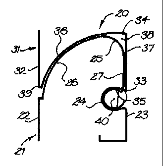
Fig. 1 shows a cross-section of a first embodiment of a hinge assembly 20 in
accordance with the present invention. Referring to Fig. 1(a), the assembly 20
includes
lower and upper hinge members 21, 31 which are pivotable relative to each
other about a
pivot axis 40.
]o The lower member 21 has a front portion 22, a rear portion 23, a
longitudinal
recess 24 adjacent the rear portion 23 which defines the pivot axis 40, and a
projection 25
extending from the front portion 22 to the recess 24. The recess 24 is formed
as a
longitudinal substantially rounded socket. The projection 25 includes an
arcuate surface
26 extending from the front portion 22, and a connection portion 27 which
extends from
[s the arcuate surface 26 to the recess 24. The arcuate surface 26 is spaced
from the axis 40
by a fixed radius (the surface 26 has the axis 40 as its centre). The front
portion 22, rear
portion 23, and projection 25 all extend longitudinally parallel to the axis
40.
The upper hinge member 31 has a front portion 32, a rear portion 33, and a
formation 34 extending from the front portion 32 to the rear portion 33. The
rear portion
20 33 includes a pivot portion 35, which is formed as a longitudinal rounded
projection,
located in the lower member recess 24 such that the lower and upper members
21, 31 can
pivot relative to each other about the hinge axis 40. The formation 34
includes an arcuate
surface 36 extending from the front portion 32, and a connection portion 37
which
extends from the arcuate surface 36 to the rear portion 33. The arcuate
surface 36 is
is spaced from the axis 40 by a fixed radius (the surface 36 has the axis 40
as its centre),
which radius is slightly larger than the radius of the arcuate surface 26. The
surface 36
also defines an entrance portion 39 which is located adjacent the front
portion 32. The
formation 34 (arcuate surface 36 and connection portion 37) defines a cavity
38 into
which the lower member projection 25 extends and moves as the lower hinge
member 21
3o pivots relative to the upper hinge member 31.
Figs. 1 (a) to 1 (h) sequentially show movement of the upper hinge member 31
relative to the lower hinge member 21. It can be seen that at substantially
the entire range
of movement of the upper member 31 relative to the lower member 21, the
entrance
portion 39 is always adjacent the arcuate surface 26. Thus, the insertion of a
person's
[R:~f.IBLL]16443.doc:FDP
CA 02494627 2005-O1-21
finger or any other object between the hinge members 21, 31 (between the
entrance
portion 39 and the arcuate surface 26) is substantially prevented.
The hinge assembly 20 can also include a longitudinal strip 41 which is
located
in a gap 44 in the pivot portion 35 to close the gap 44, which gap 44 is
formed by the
s rollforming process. The strip 4I prevents a person's fingers from being
inserted in the
gap 44 such that both front and rear sides of the sectional door will include
an insertion
prevention means.
When used with sectional garage doors, the upper member 31 is attached to the
bottom longitudinal edge of a first door panel and the lower member 21 is
attached to the
]o top longitudinal edge of a second (lower) door panel. The first and second
door panels
are then attached to each other by inserting the upper member pivot portion 35
into the
lower member recess 24, such that the first and second panels can be pivoted
relative to
each other. Thus, by using the hinge assembly 20 with a sectional garage door,
the
insertion of a person's finger between the panels, on both the front and rear
sides of the
]s sectional door, is substantially prevented when the adjacent door panels
pivot at the
curved section of the garage door track.
1n Fig. 1 (h), there is a small gap between the entrance portion 39 and the
arcuate
surface 26. This figure however represents a position where the door panels
are
perpendicular to each other, which does not occur in typical sectional garage
doors. The
Zo entrance portion 39 can be extended to avoid this gap, if required.
It can be seen that modifications can be made to the hinge assembly 20. For
example, the surface 36 does not have to be arcuate. As long as the entrance
portion 39
is spaced from the hinge axis 40 by a radius which is slightly larger than the
radius of the
arcuate surface 26, the entrance portion 39 will always be adjacent the
arcuate surface 26
2s and the insertion of objects between the hinge members 21, 31 will be
substantially
prevented. The surface 36 can therefore be of any shape as long as it provides
the cavity
38 for the projection 25.
Also, the arcuate surface 26 can be made from connected straight segments to
form a substantially arcuate surface. As long as the entrance portion 39 is
spaced from
3o the surface 26 by a short distance during movement of the upper member 31
relative to
the lower member 21, the insertion of objects between the hinge members 21, 31
will be
substantially prevented. The hinge assembly 20 is preferably made from metal
material
and formed by rollforming.
Fig. 2 shows a door panel 42 with the hinge assembly 20. The door panel 42 has
3s a panel portion 43, the upper member 31 integrally formed at the bottom
portion thereof
[R:U.IBLL]16443.doc:FDP
CA 02494627 2005-O1-21
6
and the lower member 21 integrally formed at the top portion thereof. The door
panel 42
can then be attached to another door panel 42 by inserting the pivot portion
35 into the
recess 24 of an adjacent panel, such that the panels can pivot relative to
each other to
form the garage door. The door panel 42 is preferably made from metal material
and
s formed by rollforming.
Fig. 3 shows the door panel 42 of Fig. 2 with a roller 45 and weatherstrip
adaptor
46. The roller 45 includes an axle 85 which is inserted into the pivot portion
35 after
insertion of the pivot portion 35 into a recess 24 of an adjacent panel. The
roller 45
engages the track of the garage door assembly in use to allow the door panels
to be moved
]o from the track vertical section where the door panels block the building
opening to the
track horizontal section to allow passage through the opening.
The weatherstrip adaptor 46 includes a longitudinal recess 47 and longitudinal
projection 48 which are similarly shaped as the recess 24 and the projection
25 of the
lower hinge member 21. The recess 47 and projection 48 allows the adaptor 46
to pivot
]s relative to the panel 42. The adaptor 26 is substantially co-extensive with
the door panel
42 and is attached to the lowermost panel 42 of a garage door. The adaptor 26
includes a
bottom portion 49 which abuts the ground surface when the garage door is
lowered to
protect the lowermost panel 42 and to substantially seal the garage against
rain. The
bottom portion 49 can include rubber sealing strips.
zo Fig. 4 shows a cross-section of a second embodiment of a hinge assembly 60
in
accordance with the present invention. The hinge assembly 60 is similar in
shape and
operation to the hinge assembly 20. Similar parts will therefore be referred
to with
similar reference numerals as the hinge assembly 20, but will include the
suffx "b".
Referring to Fig. 4(a), the assembly 60 includes lower and upper hinge members
zs 21b, 31b which are pivotable relative to each other about a pivot axis 40b.
The lower
member 21 b has a front portion 22b, a rear portion 23b, a longitudinal recess
24b adjacent
the rear portion 23b which defines the pivot axis 40b, and a projection 25b
extending
from the front portion 22b to the recess 24b. The projection 25b includes an
arcuate
surface 26b extending from the front portion 22b, and a connection portion 27b
which
3o extends from the arcuate surface 26b to the recess 24b. The arcuate surface
26b is spaced
from the axis 40b by a fixed radius (the arcuate surface 26b has the axis 40b
as its centre).
The front portion 22b, rear portion 23b, and projection 25b all extend
longitudinally
parallel to the axis 40b. The lower hinge member 21b also includes an
attachment portion
SOb at a bottom portion thereof for attachment to a door panel, as described
below.
[R~U.IBLL] 16443.doc:FDP
CA 02494627 2005-O1-21
7
The upper hinge member 31b has a front portion 32b, a rear portion 33b, and a
formation 34b extending from the front portion 32b to the rear portion 33b.
The rear
portion 34b includes a pivot portion 35b located in the lower member recess
24b such that
the lower and upper members 21 b, 31 b can pivot relative to each other about
the hinge
s axis 40b. The formation 34b includes an arcuate surface 36b extending from
the front
portion 32b, and a connection portion 37b which extends from the arcuate
surface 36b to
the rear portion 33b. The arcuate surface 36b is spaced from the axis 40b by a
fixed
radius (the surface 36b has the axis 40b as its centre), which radius is
slightly larger than
the radius of the arcuate surface 26b. The surface 36b also defines an
entrance portion
~0 39b which is located adjacent the front portion 32b. The formation 34b
(arcuate surface
36b and connection portion 37b) defines a cavity 38b into which the lower
member
projection 25b extends and moves as the lower hinge member 21b pivots relative
to the
upper hinge member 31 b. The upper hinge member 31 b also includes an
attachment
portion S l b at a top portion thereof for attachment to a door panel, as
described below.
~s Figs. 4(a) to 4(g) sequentially show movement of the upper hinge member 31b
relative to the lower hinge member 21b. It can be seen that at substantially
the entire
range of movement of the upper member 31b relative to the lower member 21b,
the
entrance portion 39b is always adjacent the arcuate surface 26b. Thus, the
insertion of a
person's finger or any other object between the hinge members 21 b, 31 b
(between the
2o entrance portion 39b and the arcuate surface 26b) is substantially
prevented.
The hinge assembly 60 can also include a longitudinal strip 41b which is
located
in a gap 44b in the pivot portion 35b to close the gap 44b, to prevent a
person's fingers
from being inserted in the gap 44b. The hinge assembly 60 is preferably formed
by
extrusion process, from suitable metal or plastics material.
zs Fig. 5 shows use of the second hinge assembly with a mesh sheet 70. The
bottom edge of the sheet 70 is attached to the attachment portion 51 b of the
upper hinge
member 31b, and the top edge of the sheet 70 is attached to the attachment
portion SOb of
the lower hinge member 21b, to form a door panel sub-assembly 71. A garage
door using
such sub-assemblies 71 can then be assembled by forming further sub-assemblies
71, and
so attaching such sub-assemblies 71 together by inserting the pivot portion
35b to the
longitudinal recess 24b of an adjacent (lower) sub-assembly 71.
Fig. 6 shows the hinge assembly 60 with a weatherstrip adaptor 46b, which is
similar to the weatherstrip adaptor 46 of the hinge assembly 20. The
weatherstrip adaptor
46b includes a longitudinal recess 47b and longitudinal projection 48b which
are similarly
ss shaped as the recess 24b and the projection 25b of the lower hinge member
21b. This
(R:V.IBLL] 16443.doc:FDP
CA 02494627 2005-O1-21
8
allows the adaptor 46b to pivot relative to the upper hinge member 31 b. The
adaptor 46b
is attached to the lowermost panel of a garage door. The adaptor 46b includes
a bottom
portion 49b which abuts the ground surface when the garage door is lowered to
protect
the lowermost panel and to substantially seal the garage against rain.
s Fig. 7 shows use of the hinge assembly 60 with an integrally formed mesh
sheet.
In this embodiment, the sub-assembly 71 shown in Fig. 5 is formed as an
integral sub-
assembly 71 by extrusion process from suitable metal material. Figs. 7(a) and
7(b) show
the sheet prior to expansion. The sheet 70 between the hinge members 21b, 31b
is
perforated to provide the mesh holes. Fig. 7(c) shows the sheet after
expansion. The
]o perforations in the sheet allow same to expand to form the mesh.
Fig. 8 shows a cross-section of a third embodiment of a hinge assembly 80 in
accordance with the present invention. The hinge assembly 80 is similar in
shape and
operation to the hinge assemblies 20, 60. Similar parts will therefore be
referred to with
similar reference numerals as the hinge assembly 20, but will include the
suffix "c".
]s As the hinge assembly 80 is similar in shape and operation to the hinge
assemblies 20, 60, a detailed description of the hinge assembly 80 will not be
given. The
main difference is that the hinge assembly 80 includes lower and upper hinge
members
21 c, 31 c which are attached to first and second panel pieces 82, 84,
respectively. The
panel pieces 82, 84 can be portions of door panels (as will be described below
with
Zo reference to Fig. 9) or parts which are to be attached to the door panels.
In this embodiment, the longitudinal recess 24c, the connection portion 27c
and
part of the arcuate surface 26c is formed by the lower member 21 c. The
remainder of the
arcuate surface 26c, front portion 22c and rear portion 23c is formed by the
panel piece
82. Thus, the panel piece 82 forms an extension or part of the arcuate surface
26c. In the
is upper hinge member 31c, the pivot portion 35c, the connection portion 37c
and part of the
arcuate surface 36c is formed by the upper member 31c. The remainder of the
arcuate
surface 36c, front portion 32c, rear portion 33c and entrance portion 39c is
formed by the
panel piece 84. Thus, the panel piece 84 forms an extension or part of the
entrance
portion 39c.
so Figs. 8(a) to 8(d) sequentially show movement of the upper hinge member 31c
relative to the lower hinge member 21 c. As with the hinge assemblies 20, 60,
the
insertion of a person's finger or any other object between the entrance
portion 39c and the
arcuate surface 26c is substantially prevented. The hinge assembly 80 also
preferably
includes a longitudinal strip (not shown) similar to the strips 41, 41 b,
which is located in a
3s gap 44c in the pivot portion 35c to prevent a person's fingers from being
inserted in the
[R~.~L.IBLL] 16443. doc: FDP
CA 02494627 2005-O1-21
9
gap 44c. The lower and upper hinge members 21c, 31c are preferably formed by
extrusion process from suitable metal or plastics material. The hinge members
21c, 31c
are designed to be attached to wood panels, which can form the panel pieces
82, 84.
Fig. 9 shows use of the hinge assembly 80 with two designs of wood panels. The
s hinge members 21c, 31c are attached to the top and bottom edges,
respectively, of the
wood panels 90, 91. The top and bottom edges of the wood panels 90, 91 are
shaped to
form the panel pieces 84, 82, as described above. It can be seen that the
hinge members
21c, 31c provide the pivot portions of the hinge assembly 80, whilst the
panels 90, 91
form parts of the cavity 38c and projection 25c of the hinge assembly 80.
]o Fig. 10 shows weatherstrip adaptors 92, 94 for the panels 90, 91
respectively.
These adaptors 92, 94 include a hinge member 31 c for attaching to the
lowermost panel
of the garage door, similar to the adaptors 46 described above. The front
portions of the
adaptors are shaped to correspond to the design of the corresponding panel 90,
91
Lubrication can be provided between the recess and pivot portions of the hinge
is members of the above embodiments to provide a smooth pivoting movement.
Such
lubrication can be in the form of gel lubricants, carbon tape and the like.
Although the present invention has been described with reference to particular
embodiments, it will be appreciated that numerous variations and modifications
will
become apparent to persons skilled in the art. For example, the hinge
assemblies can
zo alternatively use conventional hinges to provide pivoting movement between
the hinge
members, rather than having the recess and pivot portions. It is also possible
for the panel
top and bottom longitudinal edges to form the entire projection, cavity and
entrance
portions to prevent insertion of objects between the panels.
jR:~LIHLL] 16443.doc:FDP