Note : Les descriptions sont présentées dans la langue officielle dans laquelle elles ont été soumises.
CA 02494864 2005-02-03
WO 2004/016326 PCT/N02003/000277
GOLF CIrUB DEVICE
The invention relates to a golf club device, more
specifically a.so-called putter, which is used to hit the
golf ball the last distance to a hole.
s A putter is used, in order to hit a golf ball a relatively
short distance,. typically from a few millimetres to about
thirty metres. The putter is arranged with a club face, which
is nearly perpendicular relative to the ground surface when
the putter hits the ball, in order for the ball to roll along
o the ground.
Golf clubs that are used in competition, must have a
configuration in accordance with the rules that apply to the
game of golf. Technical solutions are known, which may help
the player to achieve optimal strokes, but the set of rules
i5 allows limited freedom of action in terms of technical means.
Known optimisation of golf clubs includes variations in the
angle of the club face, the mass and shape of the club head,
the mass, shape and rigidity of the shaft, the position of
CA 02494864 2005-02-03
WO 2004/016326 PCT/N02003/000277
2
the centre of gravity of the club head relative to the
position of the shaft attachment and the point where the face
is to hit the ball, etc.
In putting it is most important that the ball is hit in such
s a way that it gets the right initial velocity and direction
in order for the ball just to reach the hole. The initial
velocity is affected by three conditions: the velocity of the
club head as it hits the ball, the effective mass of the
putter and the position of the hitting point on the face of
io the club head.
Given the effective mass of the putter, it is the player's
ability to control the velocity of the club head and the
hitting point that distinguishes a good putt from a not so
good putt. The greatest transmission of energy from club to
25 ball is achieved when the hitting point on the face of the
club head is on the course of the centre of gravity of the
club head. With minor variations, a good player will place
the hitting point correctly, players practicing to get it to
be the same from one stroke to the other. To a trained player
ao the greatest challenge is therefore to get the right velocity
for the club head, so that the ball gets the right initial
velocity.
When putting is performed by wrist rotation, the player grips
the club with both hands at the free end of the shaft and
25 holds the club right in front of himself as he is bending
forward. By a rotation of the wrists, the club is rotated
about an essentially horizontal axis of rotation at the
wrists, and the stroke is performed without the back and the
shoulder portion moving. When putting is performed by a
so rotation of the vertebral column, the club is gripped in a
way corresponding to that in wrist rotation, but the stroke
CA 02494864 2005-02-03
WO 2004/016326 PCT/N02003/000277
3
movement is achieved by a rotation of the upper body about
the vertebral column. The club rotates about an essentially
horizontal axis at the height of the top of the vertebral
column. Experienced golfers prefer to perform a putt by.
s rotation of the vertebral column. Wrist putting is more
common among novices.
A putt normally requires very little energy, a small part of
a trained player's stroke capacity is involved. More often
than not, putts are carried out at a very low club velocity.
io It is difficult to adjust the transmission of energy in the
stroke. To increase the stability of the putter in the
stroke, known putters have a light shaft and a relatively
heavy club head, and the development has been towards heavier
and heavier club heads. The club head of a putter weighs from
zs 250 to 500 grams, whereas the shaft typically weighs from 100
to 120 grams. An increased mass of the club head has a
stabilizing effect, but it is still difficult to achieve the
right initial velocity on the golf ball. This may be caused
by the fact that a heavy club head means an increased active
ao mass transmitting energy to the ball, and even small velocity
differences in the moment of striking make noticeable
differences in the initial velocity of the ball.
The object of the invention is to provide an improved putter.
The object is realized through features as specified in the
~s~ description below and the following claims.
A putter according to the invention is stabilized by the
shaft having a large mass compared to that of known putters,
either by the shaft making up a larger part and the club head
a smaller part of the moment of mass inertia of the putter
3o about a defined axis of rotation, than in a known putter, or
CA 02494864 2005-02-03
WO 2004/016326 PCT/N02003/000277
4
by the mass of the shaft per unit of length being larger than
in a known putter.
A putter according to a first embodiment of the invention is
provided with a club head,. which has an average or small
s mass, so that the head's part of the moment of mass inertia
of the putter about the axis of rotation makes up a smaller
part of the total moment of mass inertia of the putter than
in known putters.
A putter according to a second embodiment of the invention is
io provided with a shaft which has a larger mass per unit of
length than known putters have.
The moment of inertia of a mass point rotating about an axis
of rotation is defined as the mass of the mass point
multiplied by the square of the distance between the mass
zs point and the axis of rotation. When a body rotates about an
axis of rotation, each mass point of the body will follow its
own course, so that the distance of said axis of rotation can
vary from one mass point to another. There is a well
developed set of formulas for the calculation of the moment
zo of inertia of bodies rotating about an axis, and this is well
known to a person skilled in the art. Therefore, the
theoretical basis for the moment of inertia and calculations
associated with it, will not be explained in further detail.
A putter according to the invention may have a club head of
zs any mass. A typical putter can have a club head with a mass
in the range of 225 to 350 grams and a shaft with a mass in
the range of 150 to 1500 grams or more. At the free end of
the shaft there is arranged, in a known manner, a grip with a
mass in the range of 56 to la1 grams. According to a first
so embodiment of the invention the club head makes up less than
CA 02494864 2005-02-03
WO 2004/016326 PCT/N02003/000277
80 per cent of the moment of inertia of the club when the
club rotates about an axis of rotation perpendicular to the
shaft and at a distance of about 120 centimetres from the
club head. The shaft may be provided with a displaceable
s mass, for example in the form of a tubular sleeve enclosing
the shaft, the sleeve being arranged to be attached at a
desired distance from the club head. The shaft's portion of
the moment of inertia can thereby be adjusted to the player's
stroke technique.
~o In practice the club head's portion of the moment of inertia
of the putter about the axis of rotation may be between 30
and 75 per cent. This is significantly different from known
putters, in which the club head makes up 80 per cent or more
of the moment of mass inertia of the club when the club is
is rotated about a rotational axis as indicated.
The mass of the shaft may be determined through the choice of
material and the dimensioning. Additional masses may also be
provided in the form of weights or filling substance in a
tubular shaft. The additional mass may be displaceable
~o longitudinally of the shaft, for example a displaceable
weight arranged either on the shaft or within a tubular
shaft. The moment of inertia of the shaft about the axis of
rotation, may be adjusted to a preferred value through
displacement of the weight.
Zs According to the invention, the connection between the head
and shaft of the putter may advantageously be formed as a
connection of limited elasticity. As the head of the putter
hits the ball, said elastic connection contributes to that
mainly the mass of the head gives the ball its initial
so velocity, whereas the mass of the shaft will be less
important.
CA 02494864 2005-02-03
WO 2004/016326 PCT/N02003/000277
6
As mentioned, the purpose of the invention can be realized
through a putter according to a second embodiment of the
invention, more specifically by means of a shaft of a
relatively large mass per unit of length. The total mass of
the shaft comprises the shaft and a possible displaceable
weight. More specifically, the total mass of the shaft
divided by the length of the shaft should be at least 170
grams per metre of shaft in shafts shorter than 1 metre, and
at least 190 grams per metre of shaft in.shafts longer than 1
metre.
The invention will be described in further detail below by
means of an exemplary embodiment, and reference is made to
the attached drawings, in which:
Fig. 1 shows in perspective a generalized putter with a
cylindrical shaft;
Fig. 2 shows a front view of the putter of Fig. 1;
Fig. 3 shows a front view of a putter with a displaceable
weight on the shaft;
Fig. 4 shows a front view of a putter with a conical shaft;
Fig. 5 shows, in a front view and on a larger scale, a
section through a putter head and part of a shaft.
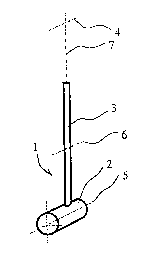
In Fig. 1 the reference numeral 1 identifies a generalized
putter comprising a head and a Cylindrical shaft 3 attached
to the head 2. Figures 1 and 2 will be used to support
reflections connected to the moment of mass inertia of the
putter 1 and how it is divided between the head 2 and the
shaft 3. To simplify the description, moment of inertia is
SUBSTITUTE SHEET (RULE 26)
CA 02494864 2005-02-03
WO 2004/016326 PCT/N02003/000277
7
used instead of moment of mass inertia below. At the free end
of the shaft 1 a grip is arranged in a known manner, but this
has not been shown as it affects the reflections to a small
degree and is not of importance to the conclusions.
s In Figures 1 and 2 the head 2 and the shaft 3 have been
simplified to a massive straight cylindrical shape to
simplify the following reflection on the moment of inertia of
the putter 1.
In a stroke, the putter I is rotated about an essentially
~o horizontal axis of rotation 4 located about 120 centimetres
from the axis 5 of the club head 2. The length of the head 2
has been chosen to be 12 centimetres and the diameter has
been chosen to be 3 centimetres. A great number of heads of
greatly varying shapes are known. For a given mass, a
is cylindrical shape with the specified dimensions represents a
putter head with a low moment of inertia about the
longitudinal axis. The distance between the axis of rotation
4 and the longitudinal axis 5 of the head 2 will vary with
the player's height and manner of playing.
ao The diameter of the shaft 3 has been chosen to be l
centimetre. The length of the shaft 3 has been chosen to be
88 centimetres, which corresponds to a good thirty-four
inches.
A transversal axis 6 halfway along the length of the shaft 3
as is thereby 75 centimetres from the axis of rotation 4 and a5
centimetres from the axis 5 of the club head.
The structure of the generalized putter 1 has otherwise been
chosen to be such that the axis of rotation 4, the
longitudinal axis 5 of the head and the transversal axis 6 of
CA 02494864 2005-02-03
WO 2004/016326 PCT/N02003/000277
8
the shaft are perpendicular to the longitudinal axis 7 of the
shaft 3.
In a stroke the putter 1 is rotated like a pendulum,
approximately as suggested in broken lines in Fig. 2, in
s which the head 2 describes an arc 8, whereas the free end of
the shaft 3 describes an arc 9 and the centre of the shaft 3
describes an arc 10.
The mass of the shaft 3 has been set at 0,15 kilograms, which
is considered to be representative of a known putter. The
mass of the head 2 has a great effect on the moment of
inertia of the putter I. Therefore, it is reasonable to look
at the division of the moment of inertia between the head 2
and the shaft 3 for two values of the mass of the head 2, the
selected values representing extreme values for a traditional
i5 putter, namely 0,25 and 0,5 kilograms respectively.
According to Steiner's theorem, the moment of inertia of the
head 2 about the axis of rotation g is given by the sum of
the moment of inertia of the head 2 about the longitudinal
axis 5 of the head and the moment of inertia of the centre of
ao gravity of the head 2 about the axis of rotation 4.
Correspondingly, the moment of inertia of the shaft.3 about
the axis of rotation 4 is given by the sum of the moment of
inertia of the shaft 3 about the transversal axis 6 and the
moment of inertia of the centre of gravity of the shaft 3
as about the axis of rotation 4. With the indexes h for the head
and s for the shaft, the moment of inertia I can be expressed
through formulas as given below, in which the letters m, d, 1
and a indicate mass, diameter, length and distance to the
axis of rotation, respectively.
CA 02494864 2005-02-03
WO 2004/016326 ~ PCT/N02003/000277
9
2 2
mh dh 2 dh 2
Ih = 2 4 '~'~hah =mh $ +ah
2 2
12 C4ds +ls ~+~Sas ms ~6 +12+as
By inserting the numerical values dh = 3 cm, 1h = 12 cm, ah =
120 cm for a first head 2 having a mass mh = 0,25 kg and for
s a second head 2 having a mass mh = 0,5 kg, it can be seen
that for a known putter 1 the moment of inertia of the head 2
about the axis of rotation 4 will be in the range of 3600-
7200 kgcm2.
For the shaft 3 are used, correspondingly, ds = 1 cm, is = 88
o cm, as = 75 cm and mass ms = 0,15 kg, which gives a moment of
inertia of the shaft 3 about the axis of rotation 4 equalling
9 41 kgcmz .
Thus, the total moment of inertia I = Ih + IS of a known
putter 1 will be in the range of 4541-8141 kgcm2 when the
s head 2 weighs from 0,25 to 0,5 kg. Thereby, the head 2 makes
up 79-88 per cent of the total moment of inertia.
For a putter 1 according to the invention, the head 2 will
constitute a smaller portion, and the shaft 3 will constitute
a larger portion of the total moment of inertia of the putter
0 1 than for a known putter.
By increasing the mass of the shaft 3 from 0,15 kg to 0,2 kg,
for example, both the moment of inertia of the shaft 3 and
the total moment of inertia of the putter about the axis of
rotation 4 will increase. If the mass of the head 2 is 0,25
s kg, the portion of the head 2 of the total moment of inertia
is reduced from 79 to 74 per cent. If the mass of the head 2
SUBSTITUTE SHEET (RULE 26)
CA 02494864 2005-02-03
WO 2004/016326 PCT/N02003/000277
is 0,5 kg, the portion of the head 2 of the total moment of
inertia is reduced from 88 to 85 per cent.
If the mass of the shaft 3 is increased to I,5 kg, the
portion of the head 2 of the total moment of inertia about
s the axis of rotation 4 will be 28 and Q3 per cent,
respectively, for a head 2 with a mass of 0,25 or 0,5 kg.
For a putter 1 according to the invention, the moment of
inertia of the head 2 about the axis of rotation a makes up
less than 79 per cent of the total moment of inertia of the
o putter about the axis of rotation 4 when the distance between
the axis of rotation 4 and the longitudinal axis 5 of the
head.2 is about 120 centimetres. The head's 2 portion of the
moment of inertia may advantageously be less than 75 per
cent.
is In Fig. 3 is shown a putter I, in which the shaft 3 is
provided with a weight Z1 arranged to be displaced along the
shaft 3 and attached at a desired distance from the head 2.
The weight 11 will form part of the total moment of inertia
of the putter I about the axis of rotation 4 and thereby
zo contribute to reduce the portion of the head 2 of the total
moment of inertia. The moment of inertia of the weight 11 is
determined by the mass of the weight II and its distance to'
the axis of rotation 4. Thereby, the head's 2 portion~of the
total moment of inertia can be adjusted through displacement
zs of the weight 11.
Fig. 4 shows an embodiment of a putter I, in which the shaft
3 is conical, so that the diameter of the shaft 3 is the
largest at its free end and the smallest at the head 2. In
practice the shaft 3 will be provided with a suitable grip at
3o the free end of the shaft 3, but the grip is not shown. A
CA 02494864 2005-02-03
WO 2004/016326 PCT/N02003/000277
11
conical shaft 3 will provide a different mass distribution
and moment of inertia from those of a cylindrical shaft of
the same masse and the same length. The moment of inertia of
the conical shaft 3 about the axis of rotation 4 is lower
than that of a corresponding cylindrical shaft. This is
essentially due to the fact that the centre of gravity of the
shaft is moved closer to the free end of the shaft 3 and
thereby closer to the axis of rotation 4. To maintain the
head's 2 portion of the total moment of inertia, the moment
.o of inertia of the head 2 must also be lower when a conical
shaft is used, as is shown in Fig. 4. This means that the
mass of the head 2 must be smaller when a conical shaft 3 is
used. The shaft 3 of the putter 1 will typically have a
circular cross-section, whether the haft is cylindrical or
is conical, but a different cross-sectional shape can also be
used.
Fig. 5 shows a section through a head 2, in which a shaft 3
is inserted into a bore 1~ of the head 2 and secured to the
head 2 by an elastic material 13, which is disposed in an
zo annular space between the head 2 and the shaft 3. The elastic
material 13 may be, for example, a ring of rubber glued to
the shaft 3 and to the head 2. The elastic material 13 may
also be an elastic moulding substance. With an elastic
connection between the head 2 and the shaft 3, the
zs contribution from the mass of the shaft 3 in the stroke is
reduced.