Note : Les descriptions sont présentées dans la langue officielle dans laquelle elles ont été soumises.
CA 02495045 2005-02-08
WO 2004/016956 PCT/US2003/024586
-1-
SELF FIXTURING ADHESIVE ATTACHMENT
BACKGROUND OF THE INVENTION
This invention relates generallyto adhesive attachment assemblies
or fixtures and related methods for securing an adhesive attachment or the
like to a supporting surface or substrate. More specifically, this invention
relates to improvements in such adhesive attachment assemblies or fixtures,
of the general type shown and described in U.S. Patents 4,302,492;
4,338,151; 4,390,546; 4,668,546; 4,778,702; and 4,822,656, and particularly
with respect to providing a simplified attachment configuration wherein post-
installation removal of a separate mounting or support fixture is not
required.
In many instances, it is necessary or desirable to attach an
attachment component or element such as a patch, threaded screw, or other
structure onto a supporting substrate. For example, it may necessary to
apply a thin patch to the skin of an aircraft or to the hull of a boat to
repair a
hole therein. Alternately, it may be desirable to mount a threaded stud or
other device onto a substrate, for example, the windshield of an automobile,
without requiring a hole to be made in the substrate. In many such cases, it
is necessary for the attachment component to be located on the substrate
with relatively high precision and further that a positive force be applied
urging the attachment component against the substrate for at least some
minimum time period to allow, for example, curing of an adhesive bonding
agent such as a curable epoxy orthe like to achieve a substantially optimized
and secure bond with the substrate.
. In the past, many different clamp and fixture devices have been
proposed for use in temporarily holding an attachment component on the
surface of a substrate during the cure time of a bonding agent. The majority
of such clamp and fixture devices have required some form of mechanical
connection to the substrate by means of screws or other mechanical
fasteners, clamping jaws, etc. However, these devices are not suited for use
with extended surface areas or for use with fragile or thin-walled substrates
CA 02495045 2005-02-08
WO 2004/016956 PCT/US2003/024586
within which surface interruptions to accommodate mechanical fastening are
not possible or desirable. Otherfixturing devices have been proposed which
rely upon suction cups for holding an attachment component in position on
a substrate, but suction cup devices are limited to use with relatively smooth-
surfaced substrates and further function to retain the attachment component
in place without exerting significant positive forces urging the attachment
component against the substrate. As a result, with suction cup devices, the
bonding agent on the substrate can be unevenly distributed and/or cure with
less than optimum bond strength.
Improved adhesive attachment devices are described and claimed
in U.S. Patents 4,302,492; 4,338,151; 4,390,546; 4,668,546; 4,778,702; and
4,822,656. More particularly, these devices disclose attachment devices
having a support fixture for temporary securement to the substrate by means
of a pressure sensitive adhesive or the like, in combination with force bias
or
spring means for applying a force urging the attachment component into
positive bearing engagement with the substrate for the cure time duration of
a selected adhesive bonding agent. The support fixture or a portion thereof
is movable between a first position with the adhesive component
substantially out of bearing engagement with the substrate to a second
position with the attachment component pressed firmly against the substrate.
An over-center mechanism constitutes the movable element in most of the
described embodiments. Following curing of the adhesive bonding agent,
the support fixture is removed from the substrate to leave the attachment
component such as a threaded bolt or the like securely bonded to the
substrate. In this regard, the pressure sensitive adhesive has a sufficient
adhesion strength for retaining the attachment component in position during
curing of the bonding agent, but insufficient adhesion strength to preclude
subsequent tear-off removal of the support fixture from the substrate.
White the improved attachment devices described in the above
referenced patents offer significant advantages in comparison with the
previous art, they have each required the support fixture which must be
CA 02495045 2005-02-08
WO 2004/016956 PCT/US2003/024586
-3-
removed and is typically discarded afterthe selected adhesive bonding agent
has cured.
The present invention relates to an improved and relatively
simplified adhesive attachment wherein removal of a support fixture
componentfrom the substrate following curing ofthe adhesive bonding agent
is not required.
SUMMARY OF THE INVENTION
In accordance with the invention, a self fixturing adhesive
attachment is provided for securely mounting an attachment component such
as a threaded stud or the like relative to the surface of a substrate. The
self
fixturing attachment comprises, in one preferred form, a base fixture carrying
the attachment component and defining a base surface for receiving a
selected bonding agent thereon. A resilient pressure sensitive adhesive
member has a first portion carried by the attachment component at a blind
side thereof, a second portion secured to the base fixture, and a third
portion
extending therebetween. Upon pressed mounting of the base fixture with the
bonding agent thereon onto the surface of the substrate, the attachment
component is movable to press the first portion of the pressure sensitive
adhesive member into adherence with the substrate, resulting in stretched
elongation of the third portion thereof to pull the base fixture with a
positive
force toward the substrate for the duration of the bonding agent cure time.
In a preferred form, the base fixture comprises a disk which is
centrally dished to define a shallow cavity at a blind side thereof, and
wherein
this shallow cavity is circumscribed by a generally annular attachment or
base surface. The attachment component comprises a threaded bolt or the
like having an enlarged head seated within said disk cavity in a position
generally circumscribed by the annular base surface, and a threaded shank
protruding through a central disk port to a front side of the base fixture. A
bolt shoulder of noncircular or square cross section or the like is positioned
within the disk port which has a mating noncircular or square cross sectional
CA 02495045 2005-02-08
WO 2004/016956 PCT/US2003/024586
-4-
shape or the like to prevent relative rotation between the attachment
component and the base fixture. The pressure sensitive adhesive member
comprises, in the preferred form, a layer of a pressure sensitive elastomer
such as that marketed by 3M Company of Minneapolis, Minnesota underthe
designation VHB Type 4910 Tape, having elastomeric bulk properties
permitting about 100% elongation without tearing and high strength acrylic
pressure sensitive adhesive on opposed surfaces. This adhesive layer
includes the first portion comprising a central region adhered to a blind side
of the bolt head, the second portion comprising a peripheral margin adhered
to the base fixture at an annular recessed shoulder formed within the disk
cavity, and an annular third portion extending therebetween.
The selected adhesive bonding agent is applied to the annular
attachment or base surface at the blind or underside of the base fixture, and
the base fixture is then press-mounted onto the substrate at a selected
location. In this initial mounted position, the pressure sensitive adhesive
layer is supported in an unstressed state by the base fixture and the
attachment component, with the adhesive layer retracted or spaced at least
slightly from the adjacent surface of the substrate. The attachment
component is then movable relative to the base fixture to press the first
portion or central region of the adhesive layer into firm pressure sensitive
adherence with the substrate. This displaces the first portion of the adhesive
layer out of alignment with the second portion or peripheral margin thereof,
resulting in stretched elongation of the intermediate third layer portion to
apply the desired force pulling the base fixture positively against the
substrate for the duration of the bonding agent cure time. Thereafter, the
base fixture supports and anchors the attachment component securely on
the substrate for normal use.
In one alternative preferred form, the pressure sensitive adhesive
member may be substituted by temporary attachment means such as a
pointed nail for securing the attachment component to the substrate, in
combination with spring means acting between the attachment component
and the base fixture for applying a positive force urging the base fixture
CA 02495045 2005-02-08
WO 2004/016956 PCT/US2003/024586
-5-
against the substrate forthe duration of the bonding agent cure time. In this
embodiment, following pressed mounting of the base fixture with bonding
agent thereon onto the substrate, the attachment component such as a
threaded bolt can be impact driven against the substrate for connecting the
bolt head to the substrate. In one form, the temporary attachment means
comprises a concrete nail carried on the bolt head for penetrating a concrete
substrate. The spring means comprises a leaf spring or the like reacting
between the threaded bolt and the base fixture, for positively urging the base
fixture toward the substrate following connection of the bolt head to the
substrate.
In a further alternative preferred form of the invention, the base
fixture may comprise the functional element of the self fixturing adhesive
attachment, wherein the attachment component supported thereby provides
means for urging the base fixture against the substrate with a positive force
for the cure time of a selected bonding agent. In this embodiment, the
attachment component comprises a button carried by the base fixture for
movement between a normal position retracted slightly from the substrate,
upon initial pressed mounting of the base fixture with bonding agent thereon
against the substrate, and an advanced position pressed firmly against the
substrate. In the advanced position, the button presses a first portion of a
resilient pressure sensitive adhesive member against the substrate in the
manner previously described, resulting in stretched elongation of a third
portion thereof to pull the base fixture against the substrate with a positive
force. Alternately, or in addition, a temporary attachment means such as a
pointed nail in combination with spring means may be provided in the manner
previously described for positively urging the base fixture against the
substrate. In one preferred form, the base fixture may comprise an electrical
junction box or the like, with multiple buttons carried thereby for pulling
the
junction box against the substrate with a positive force for the cure time of
the
bonding agent.
Other features and advantages of the invention will become more
apparent from the following detailed description, taken in conjunction with
the
CA 02495045 2005-02-08
WO 2004/016956 PCT/US2003/024586
-6-
accompanying drawings which illustrate, by way of example, the principles
of the invention.
BRIEF DESCRIPTION OF THE DRAWINGS
The accompanying drawings illustrate the invention. In such
drawings:
FIGURE 1 is a fragmented top perspective view illustrating a self
fixturing adhesive attachment in one preferred form, embodying the novel
features of the invention and shown mounted onto a substrate surface;
FIGURE 2 is an enlarged transverse sectional view of the self
fixturing adhesive attachment of FIG. 1;
FIGURE 3 is a fragmented sectional view taken generally on the
line 3-3 of FIG. 2;
FIGURE 4 is a bottom perspective view of the adhesive attachment
of FIG. 1, depicting application of a selected adhesive bonding agent to a
base fixture;
FIGURE 5 is a fragmented sectional view similar to FIG. 2, and
illustrating initial placement of the base fixture onto the surface of the
substrate;
FIGURE 6 is a fragmented sectional view similar to FIG. 5, and
showing displacement of an attachment component into temporary adhesive
engagement with the substrate for applying a positive force urging the base
fixture against the substrate for the duration of a bonding agent cure time;
FIGURE 7 is a fragmented sectional view similar to FIG. 6, and
depicting the adhesive attachment in a position bonded to the substrate;
FIGURE 8 is a fragmented top perspective view of a self fixturing
adhesive attachment in accordance with one alternative preferred form of the
invention;
FIGURE 9 is a bottom perspective viewofthe adhesive attachment
of FIG. 8, illustrating application of a selected adhesive bonding agent to a
base fixture thereof;
CA 02495045 2005-02-08
WO 2004/016956 PCT/US2003/024586
_7_
FIGURE 10 is a fragmented transverse sectional view of the
adhesive attachment of FIG. 8, illustrating initial placementofthe base
fixture
onto the surface of a substrate;
FIGURE 11 is a fragmented sectional view similar to FIG. 10, and
showing displacement of an attachment component into temporary
securement with the substrate for applying a positive force urging the base
fixture against the substrate for the bonding agent cure time;
FIGURE 12 is a fragmented sectional view similar to FIG. 11, and
depicting the adhesive attachment in a position bonded to the substrate;
FIGURE 13 is a fragmented sectional view similar to FIG. 12, and
illustrating connection of auxiliary items to the attachment component;
FIGURE 14 is a fragmented transverse sectional view similar to
FIG. 10, but showing a further alternative preferred embodiment of self
fixturing adhesive attachment in accordance with the invention;
FIGURE 15 is a fragmented sectional view similar to FIG. 14, but
showing displacement of an attachment component into temporary
securement with a substrafie, for applying a positive force urging the base
fixture against the substrate for the bonding agent cure time;
FIGURE 16 is a fragmented sectional view similar to FIG. 15, and
depicting the adhesive attachment in a position bonded to the substrate;
FIGURE 17 is a fragmented perspective view illustrating still
another alternative preferred form of a self fixturing adhesive attachment in
accordance with the present invention;
FIGURE 18 is an enlarged fragmented sectional view taken
generally on the line 18-18 of FIG. 17;
FIGURE 19 is a fragmented sectional view similar to FIG. 18, and
showing displacement of an attachment component into temporary
connection with a substrate, for applying a positive force urging a base
fixture
shown in the form of an electrical junction box against the substrate for a
bonding agent cure time;
CA 02495045 2005-02-08
WO 2004/016956 PCT/US2003/024586
_$_
FIGURE 20 is a fragmented sectional view similar to FIG. 19, and
depicting further or alternative connection of the attachment component to
the substrate;
FIGURE 21 is a fragmented sectional view similar to FIG. 20
showing the adhesive attachment bonded to the substrate;
FIGURE 22 is an enlarged and fragmented exploded perspective
view similar to FIG. 18, but illustrating a further alternative preferred form
of
the invention;
FIGURE 23 is a fragmented sectional view similar to FIG. 19,
depicting the embodiment of FIG. 22;
FIGURE 24 is a fragmented sectional view similar to FIG. 23,
showing displacement of an attachment component into temporary
connection with a substrate, for applying a positive force urging a base
fixture
shown in the form of an electrical junction box against the substrate for a
bonding agent cure time;
FIGURE 25 is a fragmented sectional view similar to FIG. 24
showing the adhesive attachment bonded to the substrate;
FIGURE 26 is a sectional view depicting another alternative
preferred form of a self fixturing adhesive attachment in accordance with the
invention;
FIGURE 27 is a fragmented sectional view showing the adhesive
attachment of FIG. 26 for use in mounting an electrical junction box or the
like onto a substrate;
FIGURE 28 is a fragmented sectional view similar to FIG. 27,
depicting displacement of a portion of the adhesive attachment into
engagement with the substrate;
FIGURE 29 is a fragmented sectional view similar to FIG. 28,
showing the electrical junction box or the like bonded to the substrate;
FIGURE 30 is a sectional view depicting still another alternative
preferred form of a self fixturing adhesive attachment in accordance with the
present invention;
CA 02495045 2005-02-08
WO 2004/016956 PCT/US2003/024586
_g_
FIGURE.31 is a fragmented sectional view showing the adhesive
attachment of FIG. 30 for use in mounting an electrical junction box or the
like onto a substrate;
FIGURE 32 is a fragmented sectional view similar to FIG. 31,
depicting displacement of a portion of the adhesive attachment into
engagement with the substrate;
FIGURE 33 is a fragmented sectional view similar to FIG. 32,
showing the electrical junction box or the like bonded to the substrate;
FIGURE 34 is a sectional view depicting a further alternative
preferred form of a self fixturing adhesive attachment in accordance with the
present invention;
FIGURE 35 is a fragmented sectional view showing the adhesive
attachment of FIG. 34 for use in mounting an electrical junction box or the
like onto a substrate; and
FIGURE 36 is a fragmented sectional view similar to FIG. 35,
depicting displacement of a portion of the adhesive attachment into
engagement with the substrate.
DETAILED DESCRIPTION OF THE PREFERRED EMBODIMENTS
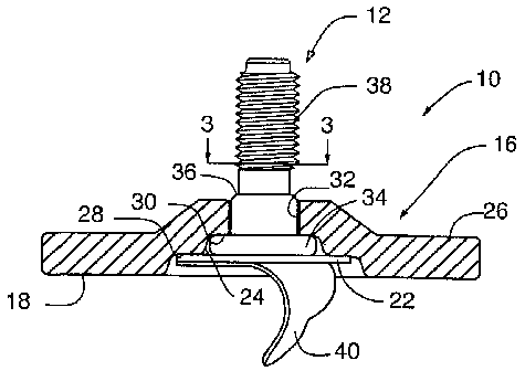
As shown in the exemplary drawings, a self fixturing adhesive
attachment referred to generally by the reference numeral 10 in FIGURE 1
is provided for quick, easy and secure adhesive mounting of an attachment
component 12 such as a threaded bolt or the like onto the surface of a
substrate 14. The self fixturing attachment 10 includes a base fixture 16
defining a blind side base surface 18 (FIGS. 2 and 4-7.) for secure bonded
fixation to the substrate 14 by means of a selected curable bonding agent 20
(FIGS. 4-7). An adhesive member 22 such as a layer of a selected pressure
sensitive adhesive material is carried jointly by the attachment component 12
and the base fixture 16, and is adapted to be stretched therebetween to
apply a positive force urging the base fixture 16 toward the substrate 14 for
the duration of a cure cycle for the bonding agent 20.
CA 02495045 2005-02-08
WO 2004/016956 PCT/US2003/024586
-10-
The illustrative base fixture 16 (FIGS. 1-7) generally comprises a
disk shaped structure which can be formed from a metal, plastic, or
composite material selected for optimum bond strength attachment to the
material of the substrate 14. FIGS. 1 and 2 depict the base fixture 16 to have
a centrally dished construction defining a shallow cavity 24 formed at a rear
or blind side thereof (FIG. 2); wherein this cavity 24 is surrounded or
circumscribed by a relatively flat annular base 26 having a blind side
defining
the base surface 18 of annular shape. The cavity 24 is shown to have a
stepped cross sectional configuration including a successive pairof generally
annular, rearwardly presented shoulders 28 and 30. A central port 32 is
formed in the disk in a position generally coaxial with the shoulders 28, 30,
and in the preferred form has a noncircular port shape such as the square
shape shown best in FIGS. 1 and 3.
The attachment component 12 is shown in the illustrative
embodiment of the invention (FIGS. 1-7) in the form of a threaded bolt,
although persons skilled in the art will recognize and appreciate that
alternative attachment components such as a patch, cable tie orthe. like may
be used. As shown, the bolt comprises a bolt head 34 having a size and
shape for nested reception into the blind side cavity 24 of the base fixture
16,
in a position seated against the radially smaller or inner shoulder 30 formed
therein. A bolt shoulder 36 projects from the bolt head 34 into and through
the central port 32 formed in the base fixture 16, wherein this bolt shoulder
36 has a noncircular shape such as the illustrative square cross sectional
shape (FIGS. 1 and 3) to fit matingly through said disk port 32 whereby
relative rotation between the bolt and support fixture are substantially
prevented. This bolt shoulder 36 is joined in turn with a threaded shank 38
which projects forwardly from and is thus exposed at a front side of the base
fixture 16.
The adhesive member 22 (FIG. 2) generally comprises a relatively
thick layerof a resilient material connected as by pressure sensitive adhesion
to the rear or blind side of the bolt head 34, and also to the base fixture 16
as by pressure sensitive adhesion to the radially larger or outer shoulder 28
CA 02495045 2005-02-08
WO 2004/016956 PCT/US2003/024586
-11-
formed therein. In this configuration, the adhesive layer 22 has a generally
circular disk shape with a first portion or central segment overlying and
adhered to the blind side of the attachment component such as the bolt head
34 as shown, a second or peripheral margin overlying and adhered to the
shoulder 28 within the base fixture cavity 24, and a generally annular third
portion extending therebetween. As shown in FIG. 2, in a normal unstressed
configuration prior to use, the adhesive layer 22 supports the attachment
component 12 in a manner to position a rear or blind side of the adhesive
layer 22 retracted or inset at least slightly from the plane of the base
fixture
surface 18. A peel-off protective strip 40 of paper or the like is desirably
provided to cover the blind side of the adhesive layer 22 prior to use.
In the preferred form, this adhesive layer 22 comprises a selected
pressure sensitive adhesive material such as that marketed by 3M Company
of Minneapolis, Minnesota under the designation VHB Type 4910 Tape,
having elastomeric bulk properties allowing 100% elongation without tearing
and a coating of high strength acrylic pressure sensitive adhesive on
opposed surfaces of the approximately 0.040 inch thick tape. In an
alternative form, in this and other embodiments of the invention to be
described herein, this pressure sensitive adhesive layer may comprise a
resilient foam material having a pressure sensitive adhesive coating on both
sides thereof for adhesion to the attachment component 12 and the base
fixture shoulder 28, and also to the substrate as will be described in more
detail.
In use, the selected bonding agent 20 such as a curable epoxy
resin or the like is applied to the annular base surface 18 of the base
fixture
16, as by means of an appropriate applicator 42 as viewed in FIG. 4. The
bonding agent 20 is preferably spread over the contact area of the base
surface 18 in a relatively uniform layer thickness, although close attention
to
layer thickness uniformity is not required. Alternately, or in addition, the
bonding agent 20 may be applied directly to a designated surface area on the
substrate. The peel-off strip 40 (FIGS. 2 and 4) is then removed from the
rear or blind side of the adhesive layer 22. The adhesive attachment 10 is
CA 02495045 2005-02-08
WO 2004/016956 PCT/US2003/024586
-12-
then pressed onto the surface of the substrate 14 at the selected mounting
site, to press the bonding agent 20 interposed between the base surface 18
and the substrate 14 into intimate surface contact with both surfaces. In this
initial mounted position, as viewed in FIG. 5, the attachment component is
in a first or retracted position relative to the base fixture, with the
adhesive
layer 22 within the base fixture cavity 24 preferably having the rear or blind
side thereof disposed in at least slightly spaced relation to the substrate
14.
As shown in FIG. 6, the attachment component 12 is then pressed
in the direction of arrow 43 to advance or push the bolt head 34 toward a
second or advanced position, in a direction toward the substrate 14. This
action displaces the attachment component 12 through a short axial stroke
relative to the base fixture 16, but without displacing the bolt shoulder 36
beyond the central port 32 in the base fixture 16, for purposes of pressing
the
first portion or central segment of the adhesive layer 22 firmly into pressure
sensitive adherence with the substrate 14. Importantly, the second portion
or peripheral margin of the adhesive layer 22 remains adhered to the base
fixture shoulder 28, such that the intermediate third portion is stretched or
elongated as viewed in FIG. 6. Such stretched elongation places the
intermediate third portion of the adhesive layer under tension to apply a
pulling force which positively draws or urges the base fixture 16 in a
direction
toward the substrate 14. The magnitude of this pulling force is on the order
of about 1 pound, and is less than the adhesion force of the adhesive layer
22 with the substrate 14, or with the base fixture shoulder 28.
This positive pulling force applied to the base fixture 16 by the
adhesive layer 22 functions to retain the entire adhesive attachment 10 in the
precise desired location on the substrate during curing of the bonding agent
20, particularly in the case wherein the substrate comprises a vertically
oriented wall surface or the like. In addition, this positive force causes the
bonding agent 20 to extrude between the fixture base surface 18 and the
substrate 14 into a relatively thin bond layer of precision uniform thickness
(FIG. 7) in intimate contact therewith to achieve a substantially optimized
bond strength between the substrate 14 and the base fixture 16. After the
CA 02495045 2005-02-08
WO 2004/016956 PCT/US2003/024586
-13-
bonding agent 20 has cured, the attachment component 12 can be used in
a normal manner, as by affixation of a threaded nut (not shown) to the
threaded shank 38 of the bolt. In this regard, the base fixture 16 is not
removed from the substrate 14 following curing of the bonding agent, but
instead remains securely fastened to the substrate for purposes of
supporting and retaining the attachment component such as the illustrative
bolt in place. Subsequent forces applied to the attachment component
during normal use may be sufficient to separate the adhesive layer 22 from
the substrate 14, but such normal usage forces are inadequate to separate
the base fixture from the substrate. Moreover, such subsequent separation
of the bolt head 34 from the substrate 14 can be beneficial in facilitating
mounting of a nut or the like to the bolt shank 38. Despite such separation,
however, the base fixture 16 retains the attachment component 12 in a
position securely mounted on the substrate 14.
One alternative preferred form of the invention is shown in FIGS.
8-13, wherein components corresponding in structure and function to those
shown and described with respect to FIGS. 1-7 are identified by common
reference numerals increased by 100. In this version of the invention, a
modified self fixturing adhesive attachment 110 includes an attachment
component 112 such as a threaded bolt or the like carried by a base fixture
116 for secure mounting onto a substrate 114. The adhesive attachment 110
includes alternative means for temporarily securing the attachment
component 112 to the substrate 114, in combination with spring means for
positively urging the base fixture 116 against the substrate for the duration
of the cure time of a selected adhesive bonding agent 120.
More particularly, the modified adhesive attachment 110 comprises
the base fixture 116 in~the form of a centrally dished disk having a generally
flat annular base 126 defining an annular base surface 118 at a blind side
thereof circumscribing a blind side cavity 124. The attachment component
112 comprises a threaded bolt having an enlarged head 134 seated within
the cavity 124, a bolt shoulder 136 of noncircular shape fitted into a
matingly
shaped central port 132 formed in the base fixture, and a threaded shank
CA 02495045 2005-02-08
WO 2004/016956 PCT/US2003/024586
-14-
138 exposed at a front side of the base fixture. Importantly, the bolt head
134 carries a downwardly projecting temporary fastener element such as a
concrete nail 44. In addition, a spring element 46 in the form of a leaf
spring
or the like is carried by the threaded shank 138 and has outboard ends for
springably engaging the top or front side of the base fixture 116, as will be
described.
In use, as viewed in FIG. 9, the blind side base surface 118 of the
base fixture 116 is coated with a selected adhesive bonding agent 120 such
as a selected curable epoxy applied from a suitable applicator 142. The
base fixture 116 is then pressed onto the substrate 114 at a selected
mounting location. In this initial press-on position, as viewed in FIG. 10,
the
temporary fastener element 44 is spaced at least slightly from the substrate
surface. Then, a suitable impact tool 48 such as a hammer or the like is
utilized to strike the end of the bolt (FIG. 11 ) to displace the attachment
component 112 in a manner to drive the fastener element 44 into at least
temporary connection with the substrate,114. In this regard, in a preferred
form of the invention, the temporary fastener element 44 comprises a
concrete nail for penetrating a concrete substrate, although alternative
temporary fastener means such as a bead of a cyanoacrylate adhesive
adapted to rupture upon impact contact with the substrate may be used.
Such displacement of the attachment component 112 relative to the base
fixture 116 partially collapses the spring element 46 which reacts between
the bolt threads and the base fixture 116 to press the base fixture 116
against the substrate 114 with a positive force. As a result, the adhesive
bonding agent 120 extrudes between the fixture base surface 118 and the
substrate 114 into a relatively thin bond layer of precision uniform thickness
(FIG. 12) to achieve a substantially optimized bond strength between the
substrate 114 and the base fixture 116. After the bonding agent 120 has
cured, the attachment component 112 can be used in a normal manner, as
by affixation of a threaded nut 50 (FIG. 13) to the threaded shank 138 of the
bolt for mounting a selected frame member 52 or other structure thereto. In
this regard, the base fixture 116 again is not removed from the substrate 114
CA 02495045 2005-02-08
WO 2004/016956 PCT/US2003/024586
-15-
following curing of the bonding agent, but instead remains securely fastened
to the substrate for purposes of supporting and retaining the attachment
component in place. Subsequent forces applied to the attachment
component during normal use may be sufficient to separate the bolt head
134 from the substrate 114, but such normal usage forces are inadequate to
separate the base fixture from the substrate.
FIGS. 14-16 illustrate a further alternative preferred form of the
invention, representing a modification of the embodiments of FIGS.1-13, and
wherein structure components corresponding with those shown and
described in FIGS. 1-13 are identified by the same reference numerals. In
this embodiment, the attachment component 112 shown in the form of a
threaded bolt includes the temporary fastener element 44 in the form of the
concrete nail or the like, as shown and described in FIGS. 8-13. The related
spring element or means for applying a positive force urging the self
fixturing
adhesive attachment against a substrate 14 comprises a resilient pressure
sensitive adhesive member 22 as shown and described in FIGS. 1-7.
More specifically, the embodiment of FIGS. 14-16 includes the
base fixture 16 having a centrally dished disk construction to define the
blind
side cavity 24 and annular blind side base surface 18 for receiving a quantity
of a selected adhesive bonding agent 20. The attachment component 112
is shown in the form of the threaded bolt having its bolt head 134 seated
within the blind side cavity, a bolt shoulder 136 protruding through a central
disk port 32 of mating noncircular shape, and an outwardly protruding
threaded shank 138. The bolt head 134 carries the downwardly projecting
temporary fastener element 44 shown in the form of a concrete nail or the
like. This pointed nail 44 is embedded within a layer 22 of a resilient
pressure sensitive adhesive material (as previously shown and described
with respect to FIGS. 1-7) wherein a first or central portion of the layer 22
overlies a blind side of the bolt head 134, a second or peripheral portion is
adhered to the base fixture 16 as by connection to a recessed shoulder 28
formed within the cavity 24, and a third intermediate portion of the layer 22
extends between these first and second portions.
CA 02495045 2005-02-08
WO 2004/016956 PCT/US2003/024586
-16-
FIG. 14 shows initial placementofthe selffixturing attachment onto
the substrate 14, with the pointed tip of the temporary fastener element 44
retracted at least slightly from the substrate surface. FIG. 15 shows
advancement of the attachment component 112 relative to the base fixture
16, as by an impact blow applied to the end of the threaded bolt, to drive the
nail 44 into at least temporary connection with the underlying substrate 14.
Such displacement also moves the central or first portion of the, adhesive
layer 22 into pressure sensitive adherence with the substrate, while
stretching the intermediate third portion of the resilient layer 22. This
results
in the stretched portion o~ the layer 22 applying a positive force to the base
fixture 16 for urging the base fixture 16 in a direction toward the substrate
14,
thereby to achieve a substantially optimized bond connection therewith. '
A further alternative preferred form of the invention is illustrated in
FIGS. 17-21, essentially comprising a functional reversal of the base fixture
and attachment component elements shown and described in FIGS. 1-16.
For ease and brevity of description, structural elements in FIGS. 17-21 which
are analogous to those shown and described in FIGS. 1-7 are identified by
common reference numerals increased by200. FIG.17 illustrates a modified
self fixturing adhesive attachment 210 to include a base fixture 216 shown
in the form of an electrical junction box adapted for secure adhesive
mounting onto a substrate 214 (FIGS. 18-21 ), in combination with a pair of
' attachment components 212 shown in the form of a button which can be
displaced relative to the box 216 for applying a positive force urging the box
216 against the substrate 214 for the cure time of a selected adhesive
bonding agent 220. In this embodiment, the base fixture shown in the form
of the junction box 216 comprises the structural element to be mounted onto
the substrate.
More particularly, the electrical junction box 216 comprises an
open-sided housing having a rear wall 60 joined at its perimeter to four
forwardly extending top, bottom and side walls 62, an opposing pair of said
walls 62 carrying inwardly bent tabs 64 (FIG. 17) along the front margins
thereof having threaded apertures 66 therein for screw-mounting of an
CA 02495045 2005-02-08
WO 2004/016956 PCT/US2003/024586
-17-
appropriately sized cover plate (not shown). The rear wall 60 of the box 216
defines a rear or blind side base surface 218 (FIGS. 18-21 ) of relatively
flat
configuration for adhesive mounting onto the surface of the substrate 214,
as will be described. This rear wall 60 has a pair of open ports 232 formed
therein, shown at diagonally opposed positions, wherein each port 232 is
formed centrally within a forwardly dished region 68 of the rear wall 60
defining a rearwardly open cavity 224.
The counterpart attachment component 212 includes a movable
button 58 mounted within each rear wall port 232. As shown, each button 58
comprises a cylindrical body having an upper end protruding through the
associated port 232, and a lower end engaging first or central region of a
resilient pressure sensitive adhesive layer 222 within the associated. dished
cavity 224. A lower end of the button 58 may be radially outwardly flanged,
as shown, to provide an extended surface area engaging the adhesive layer
222. A second or peripheral annular portion of the adhesive layer 222 is
adhered to the underside of the dished region 68 of the rear wall 60, within
the cavity 224, leaving a third or intermediate portion of the adhesive layer
extending between the first and second portions.
The attachment component 212 may also include a temporary
fastener element such as a concrete nail 72 fitted through a central bore 74
formed in the cylindrical button 58. FIG. 18 shows this nail 72 with a pointed
lower end exposed beneath the button 58 within the cavity 224, and an
enlarged head 76 located above the upper end of the button. A spring
element 78 such as a flexible flange on the button 58 is interposed between
the upper end of the button 58 and the nail head 76.
The self fixturing attachment 210 is mounted onto a substrate 214
by initially applying the selected adhesive bonding agent 220 fio the blind
side
surface 218 of the junction box 216, and then firmly pressing the box 216
against the selected substrate surface (as viewed in FIGS. 18-19). The
buttons 58 mounted within the rear wall.ports 232 at opposite corners of the
box 216 are then depressed or displaced rearwardly relative to the rear wall
60, for purposes of advancing the first or central region of the associated
CA 02495045 2005-02-08
WO 2004/016956 PCT/US2003/024586
-18-
pressure sensitive adhesive layers 222 into firm adherence with the substrate
214. As previously shown and described with respect to FIGS. 1-7, the
second or peripheral portion of the associated adhesive layers 222 remain
in adherence with the inset dished regions 68 of the rear wall 60, resulting
in
stretched elongation of the intermediate third portions to apply a positive
force urging the rearwall 60 of the junction box 216 against the substrate 214
for the duration of the bonding agent cure time. Once again, such positive
force applied to the box 216 causes the bonding agent 220 to extrude
between the blind side surface 218 and the substrate 214 into a relatively
thin
bond layer of precision uniform thickness (FIG. 21 ) to achieve a
substantially
optimized bond strength therebetween.
For additional or alternative application of positive forces urging the
rear wall 60 against the substrate 214, each nail 72 can be advanced within
the associated button 58 for embedding the pointed tip into the substrate
surface. Such advancement of the nail 72, as by applying a suitable impact
to the nail head 76 as viewed in FIG. 20, is accompanied by deformation of
the associated spring element 78 which then reacts between the nail head
76 and the dished region 68 of the rear wall 60 for urging the box 216 with a
positive force against the substrate 214. In the event that nail usage is not
required, the nail 72 may be separated from the button 58, as shown in FIG.
21.
FIGS. 22-25 show a further alternative preferred embodiment of
the invention, comprising a variation of the configuration depicted in FIGS.
18-21, and wherein functional counterpart components are identified by 300
series reference numerals. In this version of the invention, an electrical
junction box 316 includes a rearwall 360 having one or more knock-out plug
holes 80 formed therein. One or more snap ring assemblies 82 of molded
plastic or the like is provided for snap-fit mounting into the rear wall holes
80
formed upon removal of selected knock-out plugs (not shown). Each snap
ring assembly 82 comprises a dual function movable button and spring
element actuatable for positively urging the rear wall 360 of the box 316
CA 02495045 2005-02-08
WO 2004/016956 PCT/US2003/024586
-19-
against a substrate 314 for the cure time duration of a selected adhesive
bonding agent 320.
FIG. 22 shows a knock-out plug hole 80 within the rear wall 360 of
the junction box 316. The snap ring assembly 82 has an outer ring segment
83 with a size and shape for snap-fit mounting into said hole 80, preferably
with the marginal hole edge seated within a radially outwardly open annular
snap ring groove 84. From the outer ring segment 83, the snap ring
assembly 82 incorporates a relativelythin and somewhat pliable intermediate
annular segment 85 extending radially inwardly and upwardly, and then
turning downwardly to join with a central disk or button 86. An underside or
blind side surface of the button 86 carries a layer 322 of a resilient
pressure
sensitive adhesive material. A central bore 374 may also be formed in the
central button 86 for receiving a concrete nail 372 or the like having a
pointed
tip and an enlarged head 376.
The selected adhesive bonding agent 320 is applied to a rear or
blind side surface 318 of the junction box rear wall 360, whereupon the
junction box 316 is pressed firmly against the selected substrate 314, as
viewed in FIG. 23. The central button 86 of each snap ring assembly 82 is
then pressed and displaced relative to the rear wall 360 in a direction toward
the substrate 314 to firmly adhere the adhesive layer 322 to the substrate
(FIG. 24). Such displacement of the button 86 rolls the pliable intermediate
segment 85 of the snap ring assembly 82 toward the substrate whereby this
intermediate segment 85 applies a reaction force tending to pull back away
from the substrate as indicated by arrows 89 in FIG. 24. Such pulling force
is resisted by the resilient adhesive layer 322 which is thus placed under
tension. These reaction forces are transmitted through the snap ring
structures to the rear wall 360 of the box 316, to result in a positive force
urging the rear wall 360 in a direction toward the substrate. Thus, positive
pressure is applied to the bonding agent 320 to extrude that material to a
relatively thin and uniform bondline which cures with substantially optimized
bond strength (FIG. 25).
CA 02495045 2005-02-08
WO 2004/016956 PCT/US2003/024586
-20-
In the event that additional or alternative temporary securement of
the central button 86 to the substrate 314 is desired or required, such as in
the case of a concrete substrate which is somewhat dirty or dusty to preclude
adequate adhesion of the layer 322, the nail 372 can be advanced and
embedded within the substrate 314 in the manner shown and described with
respect to FIGS. 18-21. In this case, advancement of the nail 372 is
accompanied by similar rollover displacement of the intermediate segment
85 of the snap ring, resulting in .a reaction force which urges the box 316 in
a direction toward the substrate for the duration of the bonding agent cure
time.
FIGURES 26-29 show another alternative preferred form of the
invention, wherein a simplified adhesive attachment referred to generally by
the reference numeral 410 is provided for mounting a base fixture 416 (FIG.
27-29) such as an electrical junction box or other selected structure onto a
substrate 414, such as a vertical wall surface. The adhesive attachment410
is designed for assembly with the junction box 416 at the front or accessible
side of an opening or port 432 formed therein, such as a port 432 formed
upon removal of a knock-out plug (not shown) formed in a rear wall 460
thereof. Multiple attachment assemblies 410 may be used to mount a single
junction box or the like, if desired.
The adhesive attachment 410 comprises a central hub or button
458 joined to an outwardly radiating annular segment 485 which is relatively
thin and pliable, and which is in turn joined to an outer annular ring segment
483. The underside of this outer ring segment 483 is adhered to the
periphery of a pressure sensitive adhesive layer 422 such as a layer of the
VHB Type 4910 Tape (3M) shown and described previously herein. The
underside of this adhesive layer422 may be normally covered and protected
by a suitable paper peel-off strip 440 (FIG. 26). In use, the peel-off strip
440
is removed, and the underside periphery of the adhesive layer 422 is press-
adhered onto the rear wall 460 of the junction box 416 to overlie and cover
one of the ports 432 formed therein (FIG. 27). A selected adhesive bonding
agent 420 is applied to a rear or blind side surface 418 of the junction box
CA 02495045 2005-02-08
WO 2004/016956 PCT/US2003/024586
-21 -
416 (FIG. 27), and the structure is then press mounted onto the substrate
414 at the selected mounting location. The central button 458 of the
adhesive attachment 410 is pressed toward the substrate 414, as viewed in
FIG. 28, for pressing a first or central segment of the adhesive layer 422
through the port 432 into firm adherence with the substrate. In the manner
previously shown and described herein with respect to FIGS. 1-7, a second
or peripheral segment of the adhesive layer 422 remains adhered to the
attachment outer ring segment 483 at a front side of the box rear wall 460,
with a third or intermediate annular segment stretch-elongated therebetween
to apply a positive force urging the rear wall 460 of the junction box 416
against the substrate 414. This positive force causes the bonding agent 420
to extrude between the box rear surface 418 and the substrate 414 to provide
a thin and high strength cured bond layer attachment (FIG. 29).
A nail (not shown) may be carried within by the button 458 and can
be advanced and embedded within the substrate 414 in the manner shown
and described with respect to FIGS. 18-21, or removed if not needed.
FIGURES 30-33 illustrate a modified version of the adhesive
attachment shown in FIGS. 26-29, for securing a base fixture 516 such as an
electrical junction box to the surface of a substrate 514. The modified
adhesive attachment 510 of FIGS. 30-33 includes an alternative means for
temporarily securing the junction box 516 to the substrate, in combination
with a spring element for urging the box positively against the substrate for
the cure time of a selected adhesive bonding agent 520.
The adhesive attachment 510 again comprises a central hub or
button 558 joined to an outwardly radiating annular segment 585 which is
designed and shaped to provide the desired spring element, as will be
described in more detail. This annular spring segment 585 is in turn joined
to an outer annular ring segment 583. The annular underside of this outer
ring segment 583 carries a suitable pressure adhesive layer 522, the
underside of which may be normally covered and protected by a suitable
paper peel-off strip 540 (FIG. 30). In use, the peel-off strip 540 is removed,
and the underside periphery of the adhesive layer 522 is press-adhered onto
CA 02495045 2005-02-08
WO 2004/016956 PCT/US2003/024586
-22-
the rear wall 560 of the junction box 516 to overlie and cover one of the rear
wall ports 532 formed therein (FIG. 31 ), all in the same general manner as
shown and described in FIGS. 26-29. The selected adhesive bonding agent
520 is applied to a rear or blind side surface 518 of the junction box 516
(FIG. 31 ), and the structure is then press mounted onto the substrate 514 at
the selected mounting location.
In accordance with this embodiment, the central button 558 of the
adhesive attachment 510 carries a downwardly protruding fastener element
such as a pointed tip concrete nail 572. As previously shown and described
herein with respect to FIGS. 8-13 and 17-25, a head 576 of the concrete nail
572 is impacted for driving the pointed nail tip into the surface of the
substrate 514, as viewed in FIG. 32, for at least temporary connection
thereto. Such advancement of the nail 572 relative to the junction box 516
causes the annular spring segment 585 to roll upon itself in a manner to
apply a spring force positively urging the box 516 against the substrate 514
for the cure time of the bonding agent 520. Once again, this positive force
applied to the junction box 516 causes the bonding agent 520 to extrude
between the box rear surface 518 and the substrate 514 to provide a thin and
high strength cured bond layer attachment (FIG. 33).
FIGURES 34-36 show yet another alternative preferred form of the
invention, wherein a further modified adhesive attachment 610 has a
simplified spring means for applying a positive force urging a base fixture
616
such as an electrical junction box against a substrate 614 for the cure time
of a selected adhesive bonding agent 620.
The modified adhesive attachment 610 comprises a central hub or
button 658 joined to an outwardly radiating annular flange 683 which can be
formed from a suitable, relatively rigid material such as metal or plastic.
The
underside of this button/flange structure 658, 683 carries .a compressible
layer 622 of a resilient foam material which is adhered thereto by a pressure
sensitive adhesive. This resilient layer 622 also carries a pressure sensitive
adhesive on the underside thereof, whereat a peel-off strip 640 (FIG. 34) is
CA 02495045 2005-02-08
WO 2004/016956 PCT/US2003/024586
- 23 -
provided for normally protecting the adhesive from contact with dust and dirt
and other contaminants.
At the time of use, the peel-off strip 640 is removed, and the
underside periphery of the resilient layer 622 is press-adhered onto the rear
wall 660 of the junction box 616 to overlie and cover one of the ports 632
formed therein (FIG. 35). A selected adhesive bonding agent 620 is applied
to a rear or blind side surface 618 of the junction box 616 (FIG. 35), and the
structure is then press mounted onto the substrate 614 at the selected
mounting location. The central button 658 of the adhesive attachment 610
again carries a downwardly protruding fastener element such as a pointed
tip concrete nail 672. As previously shown and described herein with respect
to FIGS. 8-13 and 17-25, a head 676 of the concrete nail 672 is impacted for
driving the pointed nail tip into the surface of the substrate 614, as viewed
in
FIG. 36, for at least temporary connection thereto. Such advancement of the
nail 672 relative to the junction box 616 compresses the resilient layer 622
for applying a reaction spring force between the underside of the annular
segment 683 and the rear wall 660 of the junction box 616, for positively
urging the box 616 against the substrate 614 for the cure time of the bonding
agent 620. In the same manner as previously described with respect to
FIGS. 30-33, this positive force applied to the junction box 616 causes the
bonding agent 620 to extrude between the box rear surface 618 and the
substrate 614 to provide a thin and high strength cured bond layer
attachment.
A variety of further modifications and improvements in and to the
self fixturing adhesive attachments of the present invention will be apparent
to those persons skilled in the art. For example, while the invention has been
shown and described with respect to several specific types of attachment
structures, person skilled in the art will recognize and appreciate that a
wide
variety of alternative attachmenfi structures and devices may be employed.
Accordingly, no limitation on the invention is intended by way of the
foregoing
description and accompanying drawings, except as set forth in the appended
claims.