Note : Les descriptions sont présentées dans la langue officielle dans laquelle elles ont été soumises.
CA 02495156 2005-O1-27
TITLE
HEIGHT ADJUSTMENT MECHANISM FOR A CHAIR
BACKGROUND
This invention relates generally to height adjustable portions of chairs, and
particularly, to a height adjustment mechanism for a movable portion of a
chair. More
particularly, the invention relates to an adjustable armrest assembly.
However, the height
adjustment mechanism may also be used for other adjustable portions of a
chair, including, for
example, the back rest, or potentially even the seat.
A wide variety of adjustable office chairs are presently available. In an
attempt to adapt
the chair to a particular user or task, various adjustment mechanisms have
been provided. Such
chairs may, for example, include vertically adjustable seat height mechanisms,
swivel tilt
mechanisms, and vertically adjustable height mechanisms for armrests and
backrests.
Prior art armrest and backrest height adjustment mechanisms are available in
various
forms. In some, manually operable mechanisms, such as using buttons or
handles, which require
manipulation of a release/lock member prior to being able to adjust the arm or
back rest portion.
Examples of adjustable height armrests are described in U.S. Pat. No.
6,394,553 to McAllister,
et al, and U.S. Pat. No. 5,393,125 to Watson, et al.
Prior art mechanisms for height adjustable chair backrests are known which can
operate
"automatically," in the sense that no release or lock member need be manually
operated prior to
attempting to move the adjustable portion of the chair. In these types of
mechanisms, the
adjustable backrest can be raised or lowered and the adjustment mechanism
operates
automatically to maintain the backrest in the adjusted position.
CA 02495156 2005-O1-27
One example of such an "automatic" vertical adjustment mechanism for a chair
backrest
is described in U.S. Pat. No. 4,749,230 to Tornero. The mechanism described in
this patent
generally comprises two guided and slidably interlocking plates and one lock
pin. The lock pin
is free to move within a sinus-shaped slot defined within one plate and forced
therewith from
one locked position to a stand-by position, or to an unlocked position by the
cam action of any of
a plurality of notches and inclined surfaces of a slotted cam contained on the
other plate.
According to Tornero, this mechanism is characterized by the absence of
springs or other
supplementary biasing means. Instead of a spring member, the position of the
pin in the sinus-
shaped slot is controlled by a series of camming surfaces similar to the
notches and inclined
surfaces of the cooperating slotted cam plate. However, there is nothing which
retains the pin in
any of the positions other than the shape of the slot. This particular means
of controlling the pin
using the shape of the slot can have disadvantages. For example, rapid or
overly forceful
adjustment of the backrest could displace the lock pin to an unlocked
position, which would
require moving the backrest to the full up position in order to re-set the
lock pin in a position
where the adjustment process could be repeated. In addition, the shape of the
slot holds the pin
in each of the three positions, rather than using springs or gravity. Thus,
camming surfaces,
activated by manual force, are employed to move the pin between the three
positions defined by
the shape of the slot. Another potential disadvantage of this type of design
can be in regard to
securing the position of the pin in a particular position in the slot to
prevent the pin from
inadvertently dislodging from the notch in the slotted cam plate, such as, for
example, by
excessive or rapid application of force to the backrest, sudden movement, or
jarring of the
backrest or chair.
2
CA 02495156 2005-O1-27
Another example of an "automatic" vertical adjustment mechanism for a chair
backrest is
described in U.S. Pat. No. 5,037,158 to Crawford ("the '158 patent"), assigned
to the assignee of
the present invention. The mechanism described in the '158 patent comprises a
vertical member
containing a centrally located caroming slot that is elongated in a vertical
direction and has a
series of notches located along one side and a smooth surface located along
the other side. The
top and bottom of the caroming slot contain downwardly directed caroming
surfaces. A back
adjustment plate includes a centrally located horizontal slot and a guide pin
positioned within the
slot supported by an S-shaped leaf spring. When the guide pin is moved in
either direction away
from the central axis of the slot, the leaf spring causes the pin to be biased
in the direction that
the pin has been moved away from. In order to raise the chair back relative to
the seat, the chair
back is grasped by the user and pulled in an upward direction whereupon the
pin is urged in the
direction of the notches and registers in each of the notches as the chair
back is moved in an
upward direction. In order to lower the seat back, the seat back is raised
fully which causes the
pin to be urged in the direction of the smooth surface. As the pin rides along
the upper surface
in the direction of the smooth surface, the pin will pass the halfway point in
the slot and spring
will urge the pin in the direction of the surface. One advantage of this
particular mechanism can
be greater smoothness of operation (and thus less force to adjust the
backrest) because the slot in
which the pin rides is smooth, since no caroming surfaces are used to control
the position of the
pin therein. Other advantages can include reliability, in that the leaf spring
can more positively
control the position of the pin in the slot, making it more likely that the
pin will be maintained in
the desired position, and less likely to dislodge from that position, for
example, such as by
sudden movement or jan-ing of the chair. However, the need for the leaf spring
member itself
CA 02495156 2005-O1-27
can be a disadvantage, because it is an additional small moving part, and it
increases the cost of
the mechanism.
Consequently, there is a need for a height adjustment mechanism for adjustable
portions
of a chair, specifically the armrest, but also potentially the backrest or
seat, wherein the height
adjustment mechanism is simple, easy to use, and at the same time highly
reliable and less
costly. The present invention is directed toward filling that need.
SUMMARY
An adjustable armrest assembly is provided comprising a fixed member having a
chair
attachment portion and a housing portion, a vertically adjustable member
having an armrest
portion and a post portion, with the post portion having a lower end thereof
slidably disposed in
the housing portion, and the vertically adjustable member is selectively
movable between a fully
raised position, a fully lowered position, and at least one intermediate
position via a height
adjustment mechanism.
The height adjustment mechanism comprises a first member having a housing
portion
and a support portion, a second vertically adjustable member having an upper
end and a lower
end; the lower end being slidably disposed in the housing portion, and the
lower end further
having a camming slot formed therein. The camming slot has a plurality of
notches on one side
thereof and a generally planar surface on an opposing side. A sleeve member
can be provided in
between the housing and the post, with an inner surface of the sleeve member
adjacent opposite
sides of the camming slot. The sleeve member can have an angled slot formed in
the inner
surface thereof on opposite sides of the camming slot, such that a locking pin
can be operably
positioned through both the camming and angled slots, with opposite ends of
the locking pin
slidably captured in the angled slot. A bushing member can be provided in the
sleeve member
4
CA 02495156 2005-O1-27
such that the bushing member projects at least partially into the angled slot
such that upper and
lower regions of the angled slot are defined by the bushing member. The upper
region of the
angled slot is adjacent the generally planar surface of the camming slot,
whereas the lower
region is adjacent the plurality of notches. The camming slot further has top
and bottom
surfaces, wherein the top surface forces the locking pin across the bushing
member into the
lower region of the angled slot at the fully lowered position, and the bottom
surface forces the
locking pin across the bushing member into the upper region of the angled slot
at the fully raised
position. The locking pin being maintained in either the upper or lower
regions by the bushing
member until otherwise caused to move across the bushing member by the bottom
or top
surface. When the locking pin is maintained in the lower region of the angled
slot, gravity urges
the locking pin toward the plurality of notches, such that the locking pin is
urged into one of the
plurality of notches when such one of the notches becomes aligned with the
lower region of the
angled slot, as will occur responsive to upward vertical movement of the
armrest. The armrest is
held at a height corresponding to the notch occupied by the locking pin. The
locking pin is
moveable from whichever notch is occupied responsive to further upward
vertical movement of
the armrest, up to the fully raised position, at which the locking pin will be
urged away, by the
bottom surface of the camming slot, from the notched side of the camming slot
into the upper
region of the angled slot by the bottom surface of the camming slot. The
locking pin will be
maintained, by the bushing member, in the second region of the angled slot
until the armrest is
moved to the fully lowered position, which will result in the top surface of
the camming slot
moving the locking pin back across the bushing member into the lower region of
the angled slot.
At this point, the locking pin is positioned to repeat the selectable vertical
adjustment process by
upward vertical movement of the armrest.
CA 02495156 2005-O1-27
The adjustable armrest assembly/height adjustment mechanism, can also be
provided
with one or more compression members disposed between the outer surface of the
sleeve
member and the inside surface of the housing portion. The sleeve member can
also be a pair of
sleeve members and the bushing member can be a pair of bushing members, each
associated
with a respective sleeve member. The bushing members can partially project
only into the
angled slot formed in the sleeve member, and not into the camming slot, such
that the bushing
members contact only the ends of the locking pin which are slidably captured
in the angled slot.
The adjustable armrest assembly of can further comprise an arm pad which is
securable
to the armrest portion and has a resiliently flexible insert member. The
resiliently flexible insert
member can be a thin plate-like member having a width and length substantially
the same as the
arm pad. The thin plate-like member can be made from spring steel, or an
appropriate plastic or
other material having resiliently flexible properties.
Other details, objects, and advantages of the invention will become apparent
from
the following detailed description and the accompanying drawing figures of
certain
embodiments thereof.
BRIEF DESCRIPTION OF THE DRAWING FIGURES
A more complete understanding of the invention can be obtained by considering
the
following detailed description in conjunction with the accompanying drawings,
in which:
FIG. 1 is a side cross section view of an embodiment of an adjustable armrest
assembly according to the invention.
FIG. 2 is a right-hand exploded perspective view of an adjustable armrest
assembly such as shown in FIG. l .
6
CA 02495156 2005-O1-27
FIG. 3 is a left-hand exploded perspective view of a portion of the adjustable
armrest assembly such as shown in FIG. 2.
FIG. 4 is a view of the adjustable armrest assembly taken along line IV-IV in
FIG.
1.
FIG. 5 is a side cross section view of an embodiment of a height adjustment
mechanism according to the invention.
FIG. 6 is a bottom view of an embodiment of an arm pad for an adjustable
armrest assembly.
FIG. 7 is a section view of the arm pad taken along line VII-VII in FIG. 6.
FIG. 8 is a section view of the arm pad taken along line VIII-VIII in FIG. 6.
FIG. 9 is a section view of the arm pad taken along line IX-IX in FIG. 6.
FIG. 10 is a side view of an embodiment of a spring member for the arm pad
shown in FIG. 6.
FIG. 11 is a bottom view of the spring member shown in FIG. 10.
DETAILED DESCRIPTION OF CERTAIN EMBODIMENTS
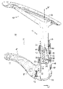
Referring now to the drawing figures, there is illustrated in FIGS. 1 and 2,
according to the present invention, an embodiment of a vertically adjustable
armrest assembly
10, including an embodiment of a height adjustment mechanism. FIG. 1 is a
cross sectional
view which shows the main elements of the height adjustment mechanism, more
details of which
are shown in the exploded views of the armrest assembly 10 in FIGS. 2 and 3.
Generally, the
adjustable armrest 10 comprises a first, vertically adjustable, wish-bone
shaped upper member
15 having an armrest portion 18, and a second, fixed, lower member 21 which
can be secured to
a chair (not shown). To effect the mounting, for example, a pair of fasteners
(not shown) can be
7
CA 02495156 2005-O1-27
inserted through a pair of bushings 23, 24 which are received in corresponding
mounting holes
26, 27. The upper member 15 has an arm pad portion 28 and a lower, downwardly
extending
post portion 30. The arm pad portion 28 is attachable to the upper member 15
via a pair of
fasteners 32, 33 and corresponding mounting holes 35, 36 in the upper member.
The lower
member 21 has a generally vertically oriented housing portion 40 and a
generally horizontally
oriented portion 43 adapted to be secured to the chair. The post portion 30 of
the upper member
15 is slidably received in the hollow housing portion 40 of the second member
21. The post
portion 30 is provided with a camming slot 45 near the lower end thereof which
is slidably
received in the housing 40 of the second member 21. The camming slot 45 is a
proportionally
narrow slot, elongated in a vertical direction extending along the lower end
of the post 30. The
camming slot 45 has a series of notches 48 along one side and a generally
smooth surface 50
along the opposite side thereof. The notches 48, defined by a series of peaks
52 and valleys 54,
are shown having a slight downward orientation, which can facilitate
maintaining the armrest in
each of the variably adjustable positions, as will be explained more fully
hereinafter. However,
the orientation could alternatively be upward or generally horizontal, i.e.,
no downward or
upward orientation. The slight downward orientation can make it slightly
easier to move the
armrest portion 18 between the various notches 48, and can also make it less
likely that an
unexpectedly large application of downward force on the armrest portion 18
would result in an
inadvertent disengagement of the height adjustment mechanism. This will be
more fully
understood hereinbelow wherein the height adjustment mechanism is described in
more detail.
It can be seen in fIGS. 1 through 3 that there is a second, angularly oriented
slot
56 which cooperates with the caroming slot 45. A lock pin 58 is also
illustrated, which is
captured both in the angled slot 56 and the caroming slot 45. As can be seen
best in FIGS. 2 and
CA 02495156 2005-O1-27
3, right and left hand views, respectively, the angled slot 56 is defined by a
pair of sleeve
members 60, 62 which are positioned adjacent, and on each side of, the post
portion 30 of the
upper member 15 of the armrest assembly 10. These sleeve members 60, 62 are
captured inside
the housing 40 of the lower member 21 of the armrest assembly 10 and surround
the outside of
the post portion 30. An outer surface 64 of the sleeve members 60, 62 abuts an
inner surface of
the housing 40, and an inside surface 66 of the sleeve members 60, 62 is held
adjacent the post
portion 30 by such inner surface. The inside surfaces of the sleeve members 66
surround the
post portion 30 and have features 68 therein which define the second, angled
slot 56 which
cooperates with the camming slot. 45 and in which the lock pin 58 is captured.
The sleeves 60, 62 can be secured axially within the housing 40 via upstops
71,
72 at lower end of each sleeve 60, 62, which cooperate with an adjacently
located shoulder 70
near the bottom of the housing 4CI. The upstops 71, 72 coact with the shoulder
70 to prevent the
sleeves 60, 62 from being drawn upwards through the top of the housing 40 as
the armrest
portion 18 is moved upwardly through the enabled range of vertical travel. A
bottom cap 74 at
the lower end of the housing 40 further secures the sleeves within the housing
40. The bottom
cap 74 can be secured to the housing via an appropriate fastener 75. The
sleeves 60, 62 could
further be secured axially within the housing 40 via a an annular lip 76 at
the top end of the
housing 40.
The lock pin 58 extends through the camming slot 45 with opposite ends thereof
captured in the angled slot 56 defined by the sleeve members 60, 62. The
second slot 56 is
angled to take advantage of gravity. Essentially, gravity causes the lock pin
58 to seek the
lower-most end of the angled slot 56, unless it is otherwise held at a
different position therein.
Unlike the height adjustment mechanism for a chair back shown in the
aforementioned '158
9
CA 02495156 2005-O1-27
patent, the present angled slot design takes advantage of gravity to control
the position of the
lock pin 58 in the second slot 56. In the '158 patent, the notches in the
camming plate are
upwardly oriented to help ensure that the pin won't, either from jarring or by
a large application
of force, become dislodged from the notch. In the design in the '158 patent
the pin is carried by
the vertical movable portion and the camming slot is stationary, whereas it is
just the opposite in
the present invention. Also, in the '158 patent the second slot is generally
horizontal, and
employs a leaf spring (instead of using gravity) to control the position of
the pin in the slot and
also to urge the pin into the notches. According to the present invention, the
second slot 56 is
angled to take advantage of gravity to cause the lock pin 58 to be naturally
disposed to take the
desired position within the geometry of a notch 48. Thus, a spring or other
resiliently
deformable member is not needed. The slight downward orientation of the
notches 48 can be
provided to make it less likely that the lock pin 58 will become dislodged
from whichever notch
48 it is engaged in by unintentional movement or an unusually large
application of force applied
to the top of the armrest portion 18.
The lower-most surface 78 of the camming slot 45 can preferably have a
slightly
downward sloping orientation to facilitate movement of the lock pin 58 to the
upper end of the
angled slot 56 in order to fully disengage the lock pin from a notch 48, and
move the lock pin 58
to a position adjacent the generally planar side 50 of the camming slot 45. As
long as the lock
pin 58 is maintained adjacent the planar side 50 of the camming slot 45, the
post portion 30, and
the armrest portion 18, can be adjusted downwards to the fullest extent, thus
resetting the height
adjustment mechanism and permitting the adjustment operation to begin again.
In order to facilitate the reset operation, allowing the armrest portion 18 to
be
moved to the fully lowered position, it can be necessary to maintain the lock
pin 58 in the upper-
CA 02495156 2005-O1-27
most position in the angled slot Sti. To accomplish this, a bushing, and in
this embodiment a
pair of generally cylindrical bushings 80, 81, are provided, one in each of
the sleeve members
60, 62. In each of the sleeve members 60, 62 the bushing 80, 81 is held in a
position in which a
portion of the bushing 80, 81 projects partially into the angled slot 56 in a
manner which
segments the angled slot 56 into two separate, upper and lower, regions on
either side of
bushings 80, 81. The bushings 80, 81 can be disposed in bushing cavities 83,
84 which are
provided through the outside surface 64 of the sleeve members 60, 62 and which
partially open
into the angled slot 56 defined on the inside surface 66 of the sleeve members
60, 62. The inner
surface ol~the housing 40 retains the bushings 80, 81 in the sleeve members
60, 62. As
described above, only a portion of the bushings 80, 81 project into the angled
slot 56, as
permitted, by design, by the partially open end of the bushing cavities in the
outside surface 64
of the sleeve members 60, 62 which cooperate with the angled slot 56 on the
inside surface 66
thereof. The extent to which the bushings 80, 81 project into the angled slot
56 can be a function
of the width of the angled slot 56, the diameter of the lock pin 58, various
tolerances, and also
can depend upon the material from which the bushings 80, 81 are made. More
particularly, the
bushings 80, 81 are intended to permit the lock pin 58 to be forcibly
displaced past the bushings
80, 81 to an upper-most position at or near the top of the angled slot 56.
This can be caused by
the angled lower surface 78 of the camming slot 45 in response to drawing the
post portion 30
fully upwards. Once in the upper-most position in the angled slot 56, the lock
pin 58 will be
retained in that position by the bushings 80, 81 until such time as the lock
pin 58 is again
forcibly urged past the bushings 80, 81 to the lower region of the angled slot
56, at which
position the lock pin 58 is again free to engage various notches 48 responsive
to vertical
movement of the post portion 30.
11
CA 02495156 2005-O1-27
The lock pin 58 can be forced back across the bushings 80, 81, readying the
armrest portion 18 for vertical adjustment once again, when the post 30 is
urged all the way to its
lower-most position. At this lower-most position, the upper most surface 85 of
the camming slot
45 forcibly drives the lock pin 58 back across the bushings 80, 81 into the
lower region of the
angled slot 56. In this position, the lock pin 58 is ready to again be cycled
through each of
notches 48 in the camming slot 45 as the armrest portion 18 is adjusted
upwardly through its
range of motion. Like the lower-most surface 78, the upper-most surface 85 of
the camming slot
45 can have a downwardly curving profile which facilitates movement of the
lock pin 58
downwardly in the angled slot 56. Both the lower-most surface 78 and the upper-
most surface
85 of the camming slot 45 could conceivably be.generally horizontal and still
accomplish the
same function, but it can require more force to be exerted on the post portion
in order to urge the
lock pin 58 across the bushings 80, 81. Thus, the angled upper 85 and lower 78
most surfaces of
the camming slot 45 function via gravity to make the movement of the lock pin
58 across the
bushings 80, 81 in the angled slot 56 smoother, and with less required
application of force to the
armrest portion 18. The bushings 80, 81 can preferably be made of a
resiliently compressible
material. This can permit the tolerances between the lock pin 58 and the
angled slot 56 to be
closer since the lock pin 58 can slightly compress the bushings 80, 81 as it
is forced thereacross
by the angled upper 85 and lower 78 most surfaces of the camming slot 45.
As the armrest portion 18 is moved upwardly through its range of vertical
adjustment, the sides of the notches 48 in the camming slot 45 displace the
lock pin 58 upwardly
in the angled slot 56 just enough to allow the lock pin 58 to clear the notch
peak 52, and then fall
down, via gravity, into the next notch valley 54. The bushings 80, 81 in the
angled slot 56 are
located in the angled slot 56 in a position to permit the lock pin 58 to move
upward within the
12
CA 02495156 2005-O1-27
angled slot 56 only sufficiently for the lock pin 58 to clear a notch peak 52.
In this regard, the
extent to which the notch peaks 52 in the camming slot 45 project outwardly,
the length of the
angled slot 56, and the position of the bushings 80, 81 in the angled slot 56
are each factors
which must be considered when designing the mechanism to permit the lock pin
58 to move in
the angled slot 56 just sufficiently to clear the notch peaks 52 and drop into
the next adjacent
notch valley 54.
An additional feature of the sleeve members 60, 62, according to the
invention, is
the provision of compression members 86, 88, 90, 92 which are provided between
the outside
surface 64 of the sleeve members 60, 62 and the inner surface of the housing
40, as shown best in
FIGS. 3 and 4. These compression members 86, 88, 90, 92 can be located in
annular grooves 94,
96, 98, 100 provided on the outside surface 64 of the sleeve members 60, 62.
The annular grooves
94, 96, 98, 100 can help to hold the compression members 86, 88, 90, 92 in
position and inhibit
migration of the compression members 86, 88, 90, 92, such as could be induced
by vibrations from
the operation of the height adjustment mechanism. In the embodiment shown, a
pair of vertically
spaced compression members 86, 88, 90, 92, are provided on the outside surface
64 of each sleeve
member 60, 62. The compression members 86, 88, 90, 92 can be designed to
create a close fit
between the sleeve members 60, 62 and the housing 40 by absorbing tolerances,
and eliminating
play between the post 30, sleeve members 60, 62, and the housing 40. A loose
fit can result in
undesirable wobbling of the post 30 within the housing 40, particularly when
the armrest portion
18 is at the fully vertically extended position.
Referring now to FIG. 5, an embodiment of a height adjustment mechanism 110 is
illustrated, which can basically comprise the same elements as height
adjustment mechanism
described previously in connection with FIGS. 1 through 4. In accordance with
the aforesaid
13
CA 02495156 2005-O1-27
description, the height adjustment mechanism 110 shown can comprise a post
portion 130 slidably
disposed in a housing portion 140, a caroming slot 145 formed in the post
portion 130, and sleeve
members 160, 162 intermediate the post portion 130 and housing 140. The sleeve
members 160,
162 can be generally identical to the sleeve members 60, 62 shown in FIGS. 1-
4, including features
on the inner surfaces thereof adjacent the caroming slot 145 which form a
second, angled slot 156
on opposite sides of the caroming slot 145. A locking pin 158 is similarly
disposed through both
the caroming 145 and angled slots 156, with opposite ends thereof captured in
the angled slot 156.
Likewise bushings 180 and 181 (not visible) are provided projecting at least
partially into the
angled slot 156 to define upper and lower regions in the angled slot 156. The
caroming slot 145
includes upper 185 and lower 178 surfaces for moving the locking pin 158
between the two regions
defined by the bushings 180, 181. Additionally, as with the sleeve members 60,
62, compression
members (not visible) can also be provided between an outer surface of the
sleeve members 160,
162 and the inside of the housing 140, for the same purposes described in
connection with FIGS. 1-
4. Essentially, the height adjustment mechanism shown can comprise the same
members and
function in the same manner as described in connection with the adjustable
armrest assembly 10.
Thus the height adjustment mechanism 110, as will be apparent to one of
ordinary
skill in the art, as described heretofore, is not to be limited to use only in
an armrest of a chair.
Especially in view of the '158 patent, the height adjustment mechanism 110
could also be used for
a vertically adjustable backrest. Although illustrated in FIGS. 1-4 as having
a round, or oval cross
section, the height adjustment mechanism 110 could be made having a flatter,
more narrow, shape
as may be more desirable if incorporated into the backrest of a chair.
Moreover, it is also
conceivable that the height adjustment mechanism 110 may possibly have
application for vertical
adjustment of the seat of a chair.
14
CA 02495156 2005-O1-27
Accordingly, the height adjustment mechanism 110 can have essentially the same
components as the height adjustment mechanism for the adjustable armrest
assembly 10 described
in connection with FIGS. 1-4, but the post portion 130 could be part of an
upper member (not
shown) which could be the upper part of a chair backrest or the underside of a
chair seat. Likewise,
the housing portion 140 could be part of a lower member (not shown) which
could be the lower
part of a chair backrest or the base of a chair.
Referring now to FIGS. 7 through 11, an embodiment of an arm pad 200 according
to the invention is shown having a resiliently flexible insert 203. The arm
pad 200 can be similar
to the arm pad portion 28 shown in FIG.1. The insert 203 can be molded into
the arm pad 200, and
can be made from, for example, spring steel, or an appropriate plastic or
other material having
resiliently flexible properties. The insert 203 can be a thin plate-like
member, and can be
attached to the arm pad 200 at front and rear portions thereof via mounting
portions 206, 207,
provided on an underside of the arm pad 200, and appropriate fasteners (not
shown). To facilitate
fastening the insert 203 to the arm pad 200, raised mounting surfaces 209, 211
can be provided on
the insert 203, such as, for example, the two mounting portions 209, 211,
shown best in FIGS. 10
and 11. The mounting portions 209, 211 mate with corresponding mounting
surfaces 206, 207 on
the arm pad 200. The insert 203 can be generally oval shaped, also shown best
in FIGS. 6 and 11,
and can preferably have the profile shown in FIG. 10. The insert 203 imparts a
firm, yet flexible
property to the arm pad 200, enhancing comfort and resiliency.
Although certain embodiments of the invention have been described in detail,
it
will be appreciated by those skilled in the art that various modifications to
those details could be
developed in light of the overall teaching of the disclosure. Accordingly, the
particular
embodiments disclosed herein are intended to be illustrative only and not
limiting to the scope of
CA 02495156 2005-O1-27
the invention which should be awarded the full breadth of the following claims
and any and all
embodiments thereof.
16