Note : Les descriptions sont présentées dans la langue officielle dans laquelle elles ont été soumises.
CA 02496432 2005-02-22
WO 2004/017844 PCT/US2003/026479
SPRING-ACTUATED, RETRACTABLE-BLADED SURGICAL SCALPEL
CROSS REFERENCE TO RELATED APPLICATIONS
The present application is based upon and claims the benefit of United
States Provisional Patent Application Serial Number 60/405,442 by Mark L.
Iske,
et al. entitled "Spring-Actuated, Retractable-Bladed Surgical Scalpel" filed
August 23, 2002, the entire contents of which is hereby specifically
incorporated
by reference for all it discloses and teaches.
FIELD OF THE INVENTION
1o The present invention relates generally to surgical cutting instruments
and, more particularly, to surgical scalpels having spring-actuated
retractable
blades.
BACKGROUND OF THE INVENTION
It is well known that existing surgical cutting implements provide a
significant potential for harm to surgeons and support personnel. That is,
with
attention directed toward the patient, rapid handling of surgical instruments
having exposed sharp edges occasionally leads to cuts and puncture wounds
with loss of integrity of surgical gloves, thereby increasing the risk of life-
2 o threatening infectious diseases.
In U.S. Patent No. 5,403,337 for "Retractable-Bladed Surgical Scalpel"
which issued to David Platts on April 04, 1995, a spring-actuated retractable-
bladed scalpel having interchangeable blades is described. Shipping and use of
this instrument has identified three difficulties. First, if the package
containing
the scalpel is dropped, there is a likelihood that the cutting edge will
pierce the
sterile package within which it is located. Moreover, only a limited number of
scalpel blades can be used with the single-size slide member, and the slide
1
CA 02496432 2005-02-22
WO 2004/017844 PCT/US2003/026479
moves with difficulty within the channel in the handle if the size of the
scalpel is
increased to accommodate additional blade sizes.
The Saf-T-Pass Retractable Scalpel, a recently marketed product from
Surgical Specialties Corporation, minimizes the risk of scalpel injury by
providing
a surgical scalpel having a blade which is deployed when a locking button
disposed on the scalpel's slide and moving therewith is pushed forward
relative
to the scalpel's handle by a user of the scalpel. A final action of rotating
the
locking button secures the slide which holds the blade in the open position.
The
blade is retracted when the locking button is rotated in the reverse direction
by
1 o the user and the slide is permitted to move under the action of a spring
thereon,
thereby shielding the blade within the handle in which it originally was
situated.
A movable slide cover prevents the slide from being moved forward until the
slide cover is drawn rearward by the user, rendering the deployment of the
surgical blade a two-step process.
Accordingly, it is an object of the present invention to provide a
retractable-bladed surgical scalpel where accidental piercing of the
sterilized
packaging is prevented when packaged scalpels are dropped or otherwise
roughly handled.
Another object of the present invention is to provide a retractable-bladed
2 o surgical scalpel which can accept a plurality of popular scalpel blades.
Still another object of the invention is to provide a retractable-bladed
surgical scalpel having smooth motion for deployment and retraction of the
cutting blade.
Yet another object of the invention is to provide a retractable-bladed
surgical scalpel for which the cutting blade may be deployed by a single
motion
by the user.
Additional objects, advantages and novel features of the invention will be
set forth in part in the description which follows, and in part will become
apparent
to those skilled in the art upon examination of the following or may be
learned by
3o practice of the invention. The objects and advantages of the invention may
be
2
CA 02496432 2005-02-22
WO 2004/017844 PCT/US2003/026479
realized and attained by means of the instrumentalities and combinations
particularly pointed out in the appended claims.
SUMMARY OF THE INVENTION
To achieve the foregoing and other objects, and in accordance with the
purposes of the present invention, as embodied and broadly described herein
the surgical scalpel having a spring-actuated retractable blade hereof
includes:
an elongated handle having a first side and a second side, a first elongated
cavity within the handle extending over the long dimension thereof and opening
1o to the outside at both a forward end and a rearward end, the first side
having an
elongated window therethrough along the long dimension of the handle and
located toward the forward end thereof and a second window therethrough
disposed toward the rearward end of the handle, the first side further having
a
first tab extending into the first cavity and located in the vicinity of the
edge of the
elongated window closest to the rearward end of the handle and a second tab
extending into the first cavity between the second window and the rearward end
of the handle; the second side having an interior elongated slot therein which
terminates before reaching the forward end of the handle and which opens to
the
outside of the handle at the rearward end thereof; a cutting blade; an
elongated
2 o slide having a first end and a second end adapted to slidably move
longitudinally
through the first cavity in the handle and to receive the cutting blade in the
region
of the first end thereof; a portion adapted to be engaged by and actuated by a
digit through the elongated window; a raised, deformable latch in the region
of
the second end on the side thereof of the digit-engaging portion for engaging
either of the first or second tabs in the handle; and a tab adapted to move
within
the slot in the second side of the handle; means for engaging and reversibly
immobilizing the slide when the slide is located in its rearwardmost position
in
the handle; and means for providing a force on the slide directed toward the
rearward end of the handle.
Benefits and advantages of the present retractable-bladed scalpel include
a scalpel which can readily accept a plurality of popular scalpel blades and
which
3
CA 02496432 2005-02-22
WO 2004/017844 PCT/US2003/026479
maintains smooth motion in the deployment of the cutting blade independent of
the size of the blade, where the cutting blade may be deployed by a single
motion of the movable slide by the user, and where accidental piercing of the
sterilized packaging containing the scalpel is avoided when the packaging is
dropped or otherwise roughly handled.
BRIEF DESCRIPTION OF THE DRAWINGS
The accompanying drawings, which are incorporated in and form a part of
the specification, illustrate the embodiments of the present invention and,
together with the description, serve to explain the principles of the
invention. In
the drawings:
FIGURE 1 is a projection view of the parts of the scalpel of the present
invention showing the two sides of the handle, the two parts of the slide, a
coil
spring, and a blade.
FIGURE 2 is a projection view of the other side of the scalpel of the
present invention shown in FIG. 1 hereof showing the two sides of the handle,
the two parts of the slide, a coil spring, and a blade.
FIGURES 3a-3e show cross sectional views of the scalpel of the present
invention in its retracted configuration.
FIGURES 4a-4d show cross sectional views of the scalpel of the present
invention in its deployed configuration.
DETAILED DESCRIPTION
Briefly, the present invention includes a surgical scalpel having a
retractable blade which may be locked in the operating or deployed
configuration
using a single digit on one hand. Improvements over existing retractable-
bladed
surgical scalpels include a device for reducing the likelihood that a packaged
and
sterilized blade can pierce the sterilization envelope as a result of rough
handling
4
CA 02496432 2005-02-22
WO 2004/017844 PCT/US2003/026479
of the package, a handle which is capable of receiving several sizes of slides
bearing cutting blades, and a handle in which the slide contact with the
handle is
minimized, thereby providing smoother operation of the surgical scalpel.
Reference will now be made in detail to the present preferred
embodiments of the invention, examples of which are illustrated in the
accompanying drawings. Identical or similar structure is identified by the
same
callouts. Turning now to FIGURE 1, an exploded projection view of the pieces
of
the present retractable-bladed scalpel is shown illustrating, in particular,
the two
sides, 10a and 10b, which comprise handle, 12, the two slide halves, 14a and
14b which comprise slide, 16, means for imparting a rearward restoring force
to
slide 16, such as a coil spring or a resilient deformable material capable of
performing this function, 18, and cutting blade, 20. Sides 10a and 10b, when
brought together, form a cavity in which slide 16 is slidably disposed. Three
windows are also illustrated in side 10a of handle 12: elongated window, 22,
and
small windows, 24a and 24b. Tab, 26, for engaging slide 16 at the location of
the termination, 28, of raised portion, 30, in the forward end, 32, thereof
when
slide 16 is in its deployed position.
FIGURE 1 also illustrates channel, 34, having stop 36 in the forward end,
38, thereof in side 10b of handle 12 in which coil spring 18 is disposed, tab,
40,
2 o disposed on side 14b of slide 16 for engaging coil spring 18 and tab, 42,
formed
on lower flange, 43, of side 10b of handle 12 for securing slide 16 in its
retracted
position. Digit-engaging portion, 44, of slide half 14a of slide 16 and
deformable
latch 46 thereon are also illustrated and will be elaborated upon hereinbelow.
FIGURE 2 shows an exploded projection view of the retractable-bladed
scalpel shown in FIG. 1 hereof from the other side thereof. Of note in the
inside,
48, of side 10a of handle 12, three 3 tabs or projections are illustrated,
50a, 50b,
and 50c, the purpose of which will be explained in detail hereinbelow. Tab 40
and the top edge, 52, of slide half 14b form slot, 54, which is adapted to
slidably
engage the lower defining portion, 56, (FIG. 1) of channel 34 on the inside,
58, of
side 10b. Raised portion, 60, (FIG. 1) and flange, 62, of side 10a of handle
12
5
CA 02496432 2005-02-22
WO 2004/017844 PCT/US2003/026479
cooperate to form a channel which slidably engages tabs, 64a and 64b, of lower
portion, 66, of slide half 14b of slide 16.
Depressions, 68a, in slide half 14b shown in FIG. 1 are adapted to receive
posts,
68b, in slide half 14a shown in FIG. 2 for joining the two slide halves
together.
Matching raised portion, 69a, and depression, 69b, capture cutout, 69c, in
blade 20 when the two slide halves are joined, thereby affixing blade 20 to
slide
16. It should be mentioned that blade 20 may be removed from slide 16 for
replacement. Further, notch, 70, in end piece, 72, of slide half 14b of slide
16 is
adapted to slidably engage flange, 74, in side 10a of handle 12, thereby
guiding
1o tab 40 which is also formed in end piece 72, in channel 34. A portion, 76,
of the
outside, 78, of side 10a is cut away to permit easier access to digit-engaging
portion 44 through window 22.
FIGURE 3a shows a schematic representation of the side view of the
assembled scalpel of the present invention with the surgical blade in its
retracted
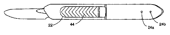
position, while FIG. 3b shows the top view thereof. Elongated window 22 and
smaller windows 24a and 24b are shown in handle 12. FIGURE 3c shows a
schematic representation of the same view as shown in FIG. 3b, except that the
top of handle 12 is removed and slide 16 is visible. FIGURE 3d is a schematic
representation of the same view as that shown in FIG. 3a except that side 10a
2 o has been removed to expose slide 16. In particular, digit-engaging portion
44 is
clearly visible on slide 16 as is spring 18 and blade 20.
FIGURE 3e shows a schematic representation of the rear view of the present
scalpel showing, in particular, the channel, 80, formed the cooperation of
raised
portion, 60, (FIG. 1 ) with flange, 62, of side 10a of handle 12 which
slidably
2 5 engages tabs, 64a and 64b, of lower portion, 66, of slide half 14b of
slide 16 (all
shown in FIG. 2), and cavity, 82, which is formed by sides 10a and 10b of
handle
12.
FIGURES 4a-4d show the same views as FIGURES 3a-3d, respectively,
except that the knife is in its extended or deployed condition. Of note is
that FIG.
30 4c illustrates the latching action of deformable latch 46 in slide half 14a
in
contact with tab 50a which secures stop 28 of slide 16 against tab 26 in
handle
6
CA 02496432 2005-02-22
WO 2004/017844 PCT/US2003/026479
12 when slide 16 is in its fully forward position. Although handle 12 and
slide 16
are fabricated as handle halves 10a and 10b and slide halves 14a and 14b,
respectively, the halves are glued or welded together by any of several well-
known joining processes as part of the assembly process for the knife.
The retractable knife of the present invention is packaged for shipment
with slide 16 is in its rearward or undeployed position, whereby tab 42 wedges
slide 16 firmly within handle cavity 82 (FIG. 3e). This prevents slide 16 from
readily moving forward such that blade 20 can puncture a sterilization
envelope if
the knife is accidentally dropped. In actual operation, latch 46 is may engage
any of tabs 50a, 50b or 50c, while being deformable such that slide 16 can
slide
through handle cavity 82 under the action of either coil spring 18 or a digit,
generally a thumb, in contact with digit-engaging portion 44. Spring 18 forces
latch 46 against whichever of the tabs the latch member is located in forward
of it
when no external force is applied to digit-engaging portion 44 of slide 16.
As stated hereinabove, handle 12 is relieved 76 in the region of window
22 to provide better access to digit-engaging portion 44 and latch 46. The
shape
of relieved portion 76 is chosen such that an operator may readily engage
digit-
engaging portion 44 of slide 16 in order to deploy blade 20, while making it
more
difficult to depress latch 46 until it is desired to retract the blade.
Therefore, latch
2 0 46 cannot easily be accidentally released by the operator during use of
the
instrument. Additionally, latch 46 may slightly extend through the rear
portion of
window 22 when slide 16 is fully deployed to more positively secure slide 16
in
its forwardmost position, without affecting the scalpel's resistance to
accidental
retraction of slide 16.
FIGURE 3c illustrates latch 44 engaging tab 50b under the action of
spring 18 such that the knife is in its closed or retracted position. Given
the
length of slide 16, this position would be attained by a user first overcoming
the
wedging action of tab 42 and moving slide 16 sufficiently far forward using
digit-
engaging portion 44 of slide 16 such that latch 46 is moved forward of tab 50b
3 o and allowed to be returned thereto under the action of spring 18.
Depressing
deformable latch 46 by inserting a solid object through window 24a will allow
7
CA 02496432 2005-02-22
WO 2004/017844 PCT/US2003/026479
slide 16 to move rearward and engage tab 50c, again under the action of spring
18. By depressing latch 46 once more, but through window 24b, slide 16 will
move rearward and out of cavity 82 under the action of spring 18, at which
time
slide 16 can be removed from handle 12 in order to exchange slides. Tab 50c
and window 24b together permit longer slides accommodating blades 20 having
different sizes and shapes to be used.
As described hereinabove, FIG. 4c illustrates the latching action of
deformable latch 46 in slide half 14a in contact with tab 50a which secures
stop
28 of slide 16 against tab 26 in handle 12 when slide 16 is in its fully
forward
z 0 position.
To improve the slidability of slide 16 within handle cavity 82, slide 16 is
kept from contacting inner walls 48 and 58 of handle 12 when the slide is
moved
by an operator of the scalpel. Tab 40 and the top edge, 52, of slide half 14b
form slot, 54, which is adapted to slidably engage the lower defining portion,
56,
(FIG. 1) of channel 34 on the inside, 58, of side 10b. Further, notch, 70, in
end
piece, 72, of slide half 14b of slide 16 is adapted to slidably engage flange,
74, in
side 10a of handle 12, thereby guiding tab 40 which is also formed in end
piece
72, in channel 34. The upper portion of slide 16 is thereby guided along the
inside of handle 12. Additionally, raised portion, 60, (FIG. 1) and flange,
62, of
side 10a of handle 12 cooperate to form channel 80 (FIG. 3e) which slidably
engages tabs, 64a and 64b, of lower portion, 66, of slide half 14b of slide
16,
thereby guiding the lower portion of slide 16 along the inside of handle 12.
Tolerances and materials are selected such that the scalpel is stable in its
operating or deployed mode yet is easily retracted. For surgical or other
medical
uses, materials must conform to Food and Drug Administration standards. For
example, scalpels must be ethylene oxide or gamma-ray sterilizable, or
autoclavable. It is anticipated that the slide and handle portions of the
present
scalpel will chosen for their moldability and for their relative coefficients
of
expansion and friction such that accurate tolerances can be maintained for
operating stability, while maintaining ready relative motion and freedom from
binding.
8
CA 02496432 2005-02-22
WO 2004/017844 PCT/US2003/026479
The foregoing description of the invention has been presented for
purposes of illustration and description and is not intended to be exhaustive
or to
limit the invention to the precise form disclosed, and obviously many
modifications and variations are possible in light of the above teaching. For
example, it would be apparent to one having ordinary skill in the surgical
arts
after carefully studying the present disclosure that the retractable knife of
the
present may be fabricated to accommodate either right- or left-handed
operators.
The embodiments were chosen and described in order to best explain the
principles of the invention and its practical application to thereby enable
others
1 o skilled in the art to best utilize the invention in various embodiments
and with
various modifications as are suited to the particular use contemplated. It is
intended that the scope of the invention be defined by the claims appended
hereto.
9