Note : Les descriptions sont présentées dans la langue officielle dans laquelle elles ont été soumises.
CA 02496737 2005-02-21
WO 2004/018838 PCT/US2003/023910
TITLE OF THC INVENTION
Gas Lift Mandrel
CROSS REFERENCE TO RELATED APPLICATIONS
Not Applicable
STATEMENT REGARDING FEDERALLY SPONSORED
RESEARCH OR DEVELOPMENT
Not Applicable
BACKGROUND OF THE iNVENTION
Field of the Invention - This invention is in the field of devices used in gas
lift
operations in oil wells.
Background Art - An oil well is drilled into a hydrocarbon bearing earth
I5 forniation, where the well is typically "completed" to allow production of
hydrocarbon material from the formation. Hydrocarbon production often begins
with
sufficient gas pressure in the formation to force the oil to the surface. As
production
fi=on1 the well continues, the reservoir usually loses pressure until
production of oil
from the well is no longer provided by the formation gas. Sometimes, the
formation
pressure is insuffcient to support production, even when the well is first
completed.
In either case, it is conimon to modify a well to allow the injection of
pressurized gas from the sui-face, to supplement the formation gas in lifting
the well
fluids to the surface. This is commonly called a "gas lift" operation. More
specifically, high pressure gas from the surface may be applied to the annulus
of the
well sun=ounding the production tubing. This gas enters the production tubing
from
the annulus, through a gas lift valving mcchanisni which is commonly
positioned in a
side pocket or bore, commonly called a valve pocket, within a mandrel.
Passagcs are
comnionly provided for the gas into the valve pocket, through the mandrel wall
from
the annulus. The valve in the valve pocket then controls the actual flow of
gas
according to its specific design. The mandrel body, sometimes called a "valve
body",
is also typically equipped with another passage, or through-bore, whicli goes
straight
through the valve body and on down the produetion tubing.
CA 02496737 2005-02-21
WO 2004/018838 PCT/US2003/023910
2
When the gas enters the production tubing via the mandrel, it can be used to
create a venturi effect and draw well fluids into the production tubing. The
gas can
also entrain itself into the well fluids, thereby lowering the specific
gravity of the
fluid and assisting in removal of the fluid froni the well. A similar mandrel
can be
used for water or chemical injection into the well, througli the tubing, from
the
surface.
The valve which actually controls gas flow is typically lowered through the
production tubing by wireline and guided into the valve pocket, such as with a
tool
commonly called a "kickover tool". This allows placement of the valve pocket
to one
lo side of the mandrel body, parallel to, but laterally offset froni the
through-bore, and
entirely out of the tllrough-bore. That is, the through-bore conimonly runs
straight
from one production tubing connection, alongside the valve pocket, to a second
production tubing connection. This parallel but offset arrangenient is
facilitated by
the use of transitional end caps or "swages" on the ends of the mandrel body.
The
end caps are refeired to as "transitional" pieccs herein, because they
transition in
diameter from small to large, on the upliole end of the mandrel body, and from
large
back to small, on the downhole end of the mandrel body. Typically, that is,
each end
cap lias a large end which matches the diameter of the valve body, and a small
end
which matches the diameter of the production tubing. The small end is offset
cotnpletely against one side of the end cap, relative to the large end. In
fact, the wall
of the small end can align with the wall of the large end, and the two ends
can have
identical wall thicknesses. So, when installed, the large end aligns with the
valve
body, while the small end aligns with the through-bore in the valve body. This
results
in straight-through flow of production fluid, while generating miniinal back
pressure.
It is desirable to have a through-bore in the mandrel which has a "full bore"
diameter, that is, where the inner diameter of tlie through-bore all the way
through the
mandrel body is at least as large as the inner diametei- of the production
tubing to
which the small ends of the mandrel end caps are connected. One reason for
this is
that it is economically very important to niaintain the inner diameter of the
fluid
production passage as large as possible, relative to the overall diameter of
the
mandrel. Another way to state this is that it is very important to minimize
the overall
diameter of the mandrel relative to the inner diameter of the tlirough-bore.
Put either
CA 02496737 2005-02-21
WO 2004/018838 PCT/US2003/023910
3
way, the point is to be able to install as small a mandrel as possible, with a
thi-ough-
bore as large as possible, to maximia.e the rate of production of fluid from a
given
diameter of well casing.
Known gas lift mandrels liave most often had the transitional end caps welded
to the valve body, or they have been one-piece mandrels, cast or machined with
intcgral end caps. Welded niandrels have higli manufacturing costs, and they
tend to
be less uniform than desired, while one-piecc niandrels havc higli tooling
costs, and
liigh capital equipment costs. In the past, attenipts to tliread the end caps
onto the
valve body have failed, because the thi-ead designs utilized were thickcr than
the wall
thickness of the components they joined, and because o-rings were required to
achieve fluid tight seals. Bulky thread sets, with wall thickness thicker than
the
joined components, had the distinct disadvantage of increasing the overall
diameter of
ihe mandrel assembly, and decreasing the diameter of the through-bore flow
path, at
least where it passed through the thread sets. This resulted in the use of a
snialler
mandrel body, and a smaller through-bore diameter, in a given size of casing.
Mandrels and other tubular components sealed with o-rings have not been
favored,
because of the tendency to lose the seal uiider harsh downhole conditions.
Tlierefore, it would be desirable to have a gas lift mandrel which operates
exactly the same as mandrels with which operators are familiar, but which
liave
separate end caps joined to the mandrel body by some process other than
welding,
where the resulting mandrel assembly has as large a through-bore dianieter as
possible, and as small an overall dianieter as possible, and where the end
caps reliably
maintain theii- seals for the life of the manch-el.
BRIEF SUMMARY OF THE iNVENTION
The present invention provides a side-pocket type gas lift mandrel in which
the transitional end caps are threaded to the mandrel body. The threads used
on each
component liave a thickness no greater than the wall thickness of the
coniponent
itself. Further, when niale and female tlireacis are threaded together, they
create a
tliread set which has a tliickness no greater than the wall thickness of
either of the two
components joined thereby. When the end caps are threaded to the niandrel body
with these threads, the overall diameter of the assembly, at the locations of
the tliread
CA 02496737 2007-07-27
4
sets, is no greater titan the overall diameter of the mandrel body itself.
Also, since the thickness of
the assembled thread set is no greater than the wall thickness of the end cap,
there is no reduction
in the inside diameter of the through-bore as it passes through the thread
set.
Accordingly, in one aspect of the present invention there is provided a gas
lift mandrel,
comprising:
a valve body having first and second ends;
valve bore formed within said valve body;
a longitudinal through-bore formed within said valve body, said through-bore
being
laterally offset from said valve bore;
first and second hollow transition pieces;
a first end on each said transition piece coaxial with said through-bore in
said valve body;
a second end on said first transition piece threaded to said first end of said
valve body;
a second end on said second transition piece threaded to said second end of
said valve
body;
a first female thread on one of said first valve body end and said second end
of said first
transition piece;
a first male thread on the other of said first valve body end and said second
end of said
first transition piece, said first male thread mating with said first female
thread to form a first thread
set;
a second female thread on one of said second valve body end and said second
end of
said second transition piece; and
a second male thread on the other of said second valve body end and said
second end of
said second transition piece, said second male thread mating with said second
female thread to
form a second thread set, wherein said first thread set has a combined wall
thickness the same as
the wall thickness of said first end of said first transition piece, and
wherein said second thread set
has a combined wall thickness the same as the wall thickness of said first end
of said second
transition piece.
According to another aspect of the present invention there is provided a
method of
manufacturing a gas lift mandrel, comprising:
forming a valve body with first and second threaded ends;
providing a valve bore within said valve body;
providing a longitudinal through-bore within said valve body, said through-
bore being
laterally offset from said valve bore;
forming first and second hollow transition pieces;
forming a first end on each said transition piece;
forming a threaded second end on each said transition piece;
threading said second end of said first transition piece to said first end of
said valve body;
threading said second end of said second transition piece to said second end
of said
valve body;
aligning said first end of each said transition piece coaxially with said
through-bore in said
valve body;
CA 02496737 2007-07-27
4a
forming a first female thread on one of said first valve body end and said
second end of
said first transition piece;
forming a first male thread on the other of said first valve body end and said
second end
of said first transition piece, said first male thread mating with said first
female thread to form a first
thread set;
forming a second female thread on one of said second valve body end and said
second
end of said second transition piece; forming a second male thread on the other
of said second
valve body end and said second end of said second transition piece, said
second male thread
mating with said second female thread to form a second thread set;
dimensioning the thickness of said first male thread and the thickness of said
first female
thread to form said first thread set with a combined wall thickness the same
as the wall thickness
of said first end of said first transition piece; and
dimensioning the thickness of said second male thread and the thickness of
said second
female thread to form said second thread set with a combined wall thickness
the same as the wall
thickness of said first end of said second transition piece.
The novel features of this invention, as well as the invention itself, will be
best understood
from the attached drawings, taken along with the following description, in
which similar reference
characters refer to similar parts, and in which:
BRIEF DESCRIPTION OF THE SEVERAL VIEWS OF THE DRAWINGS
Figure 1 is a longitudinal section view of a gas lift mandrel according to the
present
invention;
Figure 2 is a transverse section view of the gas lift mandrel of Figure 1,
taken at the line
2-2; and
Figure 3 is an enlarged section view of one end of the gas lift mandrel of
Figure 1.
DETAILED DESCRIPTION OF THE INVENTION
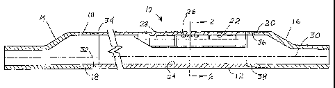
As shown in Figure 1, one embodiment of a gas lift mandrel assembly 10
according to the
present invention includes a mandrel body or valve body 12, and upper and
lower transitional end
pieces or end caps 14, 16. Each end cap 14, 16 has a smaller end with an axis
offset from the
axis of a larger end. An upper thread set 18 joins the lower, larger end of
the upper transitional
piece 14 to the upper end of the valve body 12. Similarly, a lower thread set
20 joins the upper,
larger end of the lower transitional piece 16 to the lower end of the valve
body 12.
A longitudinally oriented valve pocket or valve bore 22 is welded, machined,
or otherwise
formed, within the valve body 12. The valve bore 22 is positioned next to one
side of the valve
body 12. A full bore, or full diameter, through-bore 24 is formed
longitudinally through the valve
body 12, next to the opposite side of the valve body 12. The valve pocket axis
28 is parallel to, but
laterally offset from, the through-bore axis 30, both of which are parallel
to, but laterally offset from,
the axis of the valve body 12.
CA 02496737 2005-02-21
WO 2004/018838 PCT/US2003/023910
Fui-thcr, as can also be seen in Figure 2, the valve pocket bore 22 itself is
entirely laterally offset from the through-bore 24. A plurality of ports 26
communicate gas flow between the valve pocket bore 22 and the annulus
sttrrounding
the valve body 12. A valve (not shown) which can be positioned in the valve
bore 22
s would be used to control flow through these ports 26. The valve body 12 is
shown in
Figure 2 as a solid cylinder with longitudinal bores 22,24 and transverse
bores 26
theretlirougli, but other forms of construction could also be used without
departing
from the present invention.
Referring again to Figure 1, low profile female threads 32,36 are formed at
the
upper and lower ends of the valve body 12. Low profile male threads 34 are
formed
at the lower, larger, end of the upper transition piece or end cap 14.
Similarly, low
profile male threads 38 are formed at the upper, larger, end of the lower
transition
piece or end cap 16. Alternatively, female threads could be formed on the end
caps
14,16, and male threads could be fortned on the valve body 12, without
departing
t5 froni the present invention. These low profile threads are capable of
achieving a
liquid tight seal witli metal-to-metal contact, as is known in conunonly
available
"premium threads" in the prior art. This eliminates any need for an o-ring in
the
fitting. Further, these low profile threads mate together to result in a
thread set which
has a tliickness no greater than the wall thickness of each of the components
joined
thereby.
As can best be seen in Figure 3, provision of a low profile male thread 34
adjacent to the lower end 40 of the upper end cap 14, and provision of a low
profile
female thread 32 adjacent to the upper end 42 of the valve body 12, results in
a low
profile thread set 18 at this location. The outside diameter ODi of the thread
set 18 is
no greater than the outside diameter OD2 of the valve body 12 itself.
Therefore, use
of the low profile tlu=ead set 18 avoids any increase in the overall outside
dianieter of
the mandrel assembly 10, allowing the use of a valve body 12 as large as
possible in a
given size casing, As can best be seen in Figures 2 and 3, the low profile
thread set
I 8 has a thickness no greater than the wall thickness Ti of the upper end of
the valve
body 12, and no greater than the wall thickness T2 of the ttpper end of the
upper end
cap 14. Therefore, use of the low profile thread set 18 avoids any decrease in
the
inside diameter ID2 of the through-bore 24, relative to the inside diameter
lDi of the
CA 02496737 2005-02-21
WO 2004/018838 PCT/US2003/023910
G
upper end of the upper end cap 14. This provides a tlirough-bore 24 as large
as
possible, for a given valve body 12. Identical results are achieved at the
joint between
the lower end cap 16 and the lower end of the valve body 12.
While the particular inventian as herein shown and disclosed in detail is
fully
capable of obtaining the objects and providing the advantages hereinbefore
stated, it
is to be understood that this disclosure is merely illustrative of the
presently preferred
embodiments of the invention and that no limitations are intended otlier than
as
described in the appended claims.