Note : Les descriptions sont présentées dans la langue officielle dans laquelle elles ont été soumises.
CA 02497329 2005-02-16
1
A FLEXIBLE FLOOR AND A CORRIDOR CONNECTION TNCLUDING THE
FLOOR
The present invention relates to a flexible floor
designed for a gangway corridor connection for
intercommunication. between two cars, and more
particularly designed for rail vehicles such as trains.
subway trains, trams, etc., or more generally for any
rail or non-rail moving assembly. The present invention
also relates to a corridor connection including such a
flexible floor.
Certain known. devices require doors and do not
provide any protection from cold and noise, while others
use a system made up of a protective bellows and of a
metal floor, with all the ensuing problems of metal
slides and hinges in the floor.
Other devices require space to be dedicated to them
in the ends of the bodies for the purpose of receiving
the floor systems.
Most devices require mechanical load take-up or load
bearing systems, e~.g. bearing on the coupling bar. using
such known devices is not without problems relating to
maintenance, to wear, to noise, to lack of compactness,
to cleaning, e.g. for draining cleaning water, or to
cavities in which various objects can build up.
Flexible flocrs also exist that are connected to a
bellows, the flexible floor and the bellows forming a
corridor connection module that is self-supporting. Such
a flexible floor is known, for example, from European
Patent EP 860 305.
In the current state of the art, implementing such a
floor whose weight is supported by the bellows requires
mechanical couplings between the bellows and the raised
edges of the floor. In addition to being visible, such a
coupl.z.ng suffers from the drawback of providing no
sealing, and therefore of offering only a very small
amount of noise attenuation at the coupling between the
floor and the bellows.
CA 02497329 2005-02-16
2
An object of the present invention is to provide a
flexible floor for a corridor connection which, while
maintaining its properties as regards requirements due to
displacements between the bodies of the cars, offers
better noise attenuation and improved appearance.
In the Application below and by definition, the
horizontal direction of movement in a straight line o~
the moving assemb:Ly is considered to be longitudinal, and
the horizontal direction perpendicular to the
longitudinal direction is considered to be transverse.
The invention thus provides a flexible floor
designed to be suspended from an undulating flexible
bellows in order t:o form a corridor connection module,
said floor presenting undulating raised edges at its
transverse ends, and, on its bottom face, transverse ribs
in which metal reinforcements are embedded, said floor
being characterized in that at least some of the metal
reinforcements have ends that project beyond the
transverse ribs, each of which projecting ends is coupled
to a fastening device for fastening the floor to the
bellows, which fa~otening device extends alongside the
outside of the corresponding undulating raised edge and
presents a fastening end for fastening to the bellows
that is situated above the corresponding raised edge.
This structure thus makes it possible for the floor
to be coupled mechanically to the bellows via the
outside, independently of the coupling between the raised
edges and the bellows, which coupling can be achieved
easily in sealed manner and thus under good noise
conditions since the mechanical function of supporting
the floor no longer needs to be provided thereat.
zn addition, the mechanical coupling to the bellows,
implemented on the outside, and separately from the
coupling between the raised edges of the floor and the
bellows, also makes it possible, e.g. by means of
fastening using bolts, to maintain good soundproofing
qualities.
CA 02497329 2005-02-16
3
The raised edges are advantageously disposed in a
bend region of the floor.
In another advantageous embodiment, the floor is
characterized in that at least one fastening device is a
load take-up bar having a first end provided with a
fastening element for fastening to a respective one of
said projecting ends, and a second end provided with a
fastening element for fastening to an undulation of the
bellows. For example, the load take-up bar presents a
rounded first reg:Lon carrying, at said first end, a
fastening element for fastening to a respective one of
said projecting ends, and a second region extending
upwards and terminated at said second end by a fastening
element for fastening to an undulation of the bellows.
At least one fastening element may be designed to be
fastened by bolts.
the invention also relates to a corridor connection
Comprising at lea:~t one corridor connection module
including a flexible floor according to any preceding
claim, and an undulating flexible bellows, said corridor
connection being characterized in that the fastening ends
of the fastening devices are secured to the bellows, and
in that the undulating raised edges of the floor are
secured in sealed manner to the undulations of the
undulating flexible bellows in respective regions of
complementary geometrical shape that are mutually
overlapping.
Preferably, the overlap between said regions of
complementary geometrical shape is situated in a bottom
bend region of the: corridor connection module.
The securing between the undulating raised edges and
the undulating flexible bellows is advantageously
performed by heat-sealing.
Said fastening devices are advantageously secured to
the bellows by bolts.
CA 02497329 2005-02-16
4
The corridor connection may comprise two said
corridor connection modules assembled together
longitudinally via a coupling ring.
In known manner, the ends of a longitudinal module
may be equipped with metal and/or composite parts making
it possible to fasten said module to the body and/or to
the coupling ring.
Other characteristics and advantages of the
invention appear more clearly on reading the following
description with :reference to the accompanying drawings,
in which:
Figure 1 is ~~ perspective view of a first embodiment
of a corridor connection module of the invention;
Figures 2a and 2b are respectively a cross-section
view and a plan view of an embodiment of a floor of the
invention, Figure 2c being an enlargement of a detail of
Figure 2b, showing the floor from its top portion where
it is heat-sealed to the bellows;
Figures 3a axed 3b are respectively a cross-section
view and a side v'_ew of an embodiment of a corridor
connection bellowF; associating two corridor connection
modules; and
Figures 4a to 4c are section views showing the
couplings, between the floor and the bellows, Figure 4a
being a detail of Figure 3a, Figure 4b showing a detail
of the heat-sealed junction, and Figure 4c showing the
weatherstrip seals' 37 between the bellows and the car.
In known manr~er, a corridor connection bellows
equipped with a flexible floor is made up of at least one
corridor connection module, each such module having a top
portion or deforma.ble bellows 1 having undulating
regions, and a bottom portion or floor 2. The bellows 1
and the floor are made from an elastomer mixture in which
textile reinforcement elements can be embedded (for the
bellows) and metal can be embedded that is caused to
adhere to the mixture (for the floor).
CA 02497329 2005-02-16
The bellows 7. and the floor 2 are different pieces
which are assembled together to form a corridor
connection module which constitutes a structure having a
closed perimeter ~~nd that is preferably self-supporting.
5 In corridor connections currently in existence (in
particular on the METEOit Line in Paris), mechanical
assembly is perfo~~ned at the raised edges, which gives
rise to constraints and to drawbacks:
- since the t:loor is supported by the bellows, the
mechanical coupling can be provided only in vertical or
substantially vertical regions of the side edges of the
bellows, which requires the raised edges of the floor to
extend to a region of the bellows that is substantially
vertical; this complicates manufacturing of the floor,
due to the technical constraints involved in molding
raised edges that, at their ends, extend substantially
vertically; and
- since the mechanical coupling is provided at the
overlap between tr.e raised edges and the bellows, the
coupling is not sealed, and therefore the external noise
is not damped, hence the level of soundproofing is low.
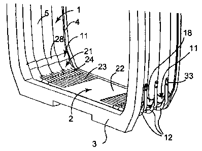
In conventional manner, a corridor connection of the
invention (Figure 1~ comprises an undulating bellows 1
presenting long undulations 5, and a flexible floor 2.
It is distinguished by the fact that the flexible floor 2
is suspended from the bellows 1 by load take-up bars 12
which provide suspender couplings via the outside, above
the overlapping zones 11 between the top ends 28 of the
raised edges 21 of the floor and the bottom ends 18 of
the bellows 1.
In this way, the suspension and sealing functions
are dissociated, and the mechanical coupling elements are
not very visible from the inside of the corridor
connection.
In known manner, the floor 2 can have a treaded
central region 22 enabling passengers to pass through,
and, on either side of said region 22, an undulating zone
CA 02497329 2005-02-16
6
made up of short undulations 23 which terminate at their
ends 24 by long undulations that foxzn the raised edges 21
(Figures 1 and 2b) and that, at least at their ends 28
situated in the overlapping regions 11, have a
geometrical shape that is complementary to the
geometrical shape of the undulations 5 at the
corresponding bottom ends 18 of the bellows 1 so as to
form sealed couplings, e.g. by heat-sealing. In each
region 11, reference 18 designates the overlapping end of
the bellows, and reference 2B designates the overlapping
end of the floor.
The corridor connection module shown in Figure 1 is
fixed to the body 3 at one of its longitudinal ends, and,
at its other longitudinal end, to a ring 4 for coupling
it to another corridor connection module, the two modules
as assembled together constituting the corridor
connection.
As shown in Figure 3a, the corridor connection
presents a closed periphery constituted by a top face 14
that is plane or slightly concave (as seen from the
inside), by two tcp bends 15, by two vertical side faces
16 that are plane or slightly concave, and by two bottom
bends 17 for coupling to the floor 2 which presents a
load-bearing face 22. 23.
As also shown in Figure 3a, the sealing coupling
between the floor 2 and the bellows 1 is situated in the
region of the bottom bend 17, which makes it possible to
limit the extent to which the raised edges 21 rise. It
can also be seen that, because of the fact that the
sealing coupling is formed in this region of each bend
17, the end 25 of the corresponding raised edge 21 is
situated in a bend region 29 and presents a direction
that slopes relative to the vertical unlike in the prior
art, in which, in order to provide the mechanical
function of suspending the floor 2, the raised edges must
extend to a vertical side edge so that their ends extend
substantially vertically.
CA 02497329 2005-02-16
7
As a result, with the invention, a considerable
advantage is procured for the molding of the floor,
since, during such molding, the ends of the raised edges
are lower, and thEay do not extend vertically.
Figure 3a al:;o shows that the mechanical couplings
whereby the floor 2 is suspended by the bellows 1 are
formed in the side faces 16 that are substantially
vertical (ignoring the curvature of the faces 16), above
the regions 11 of overlap between the ends 18 and 28 of
the bellows 1 and of the floor 2.
This separation in space between said couplings
makes it possible to provide a sealed coupling, e.g. by
heat-sealing, between the bellows 1 and the floor 2 at
the overlap coupl_Lng 11, hence the attenuation of
external noise is improved. Such heat-sealing can be
performed subsequently in a mold.
The mechanical couplings for suspending the floor 2
are explained below with reference to Figures 3b and 4a.
In known manner, in its bottom portion, the floor 2
presents transver~~e ribs 27 in which metal reinforcements
are embedded. In the invention, at least some of said
metal reinforcements 25 also serve as supporting arms,
and, at their ends;, present projecting regions 26 making
it possible to receive the load take-up bars 12. As
25 shown in the example of Figure 3b, one in every two metal
reinforcements 25 also serves as a supporting arm.
Each load ta)<:e-up bar 12 is fastened at one end 31
to a projecting region 26, e.g. by bolts 32, and at its
other end 33 to the bellows 1. The fastening to the
bellows 1 can be achieved by bolts 34. Said fastening
takes place preferably at the troughs of the undulations
of the bellows 2 a.s seen from the inside, i.e. at the
crests of the undulations as seen from the outside.
For example, each load take-up bar 12 presents a
first bend region 35 and a coupling tab 36 extending
substantially vertically. As shown in Figure 4a, the
mechanical fastening thus achieved via the outside
CA 02497329 2005-02-16
8
substantially doer not project beyond the outside
periphery of the <:orridor connection.
The mechanical fastening to the bellows makes it
possible for good fluid-tightness and soundproofing to be
achieved because raid fastening is provided outside the
overlap region 11,.
The bolts 34 pass through openings provided in the
bellows 2 and the fastening implements a backing plate 35
that stiffens the resulting assembly and contributes to
improving the fluid-tightness and the soundproofing.
Another advantage is that the floor is removable, it
being possible for. the heat-sealed coupling between the
floor 2 and the bEallows 1 to be unsealed after the bolted
mechanical coupling has been released.