Note : Les descriptions sont présentées dans la langue officielle dans laquelle elles ont été soumises.
CA 02497533 2005-03-02
WO 2004/023249 PCT/US2003/027506
[0001] A METHOD AND SYSTEM FOR USER INITIATED
INTER-DEVICE, INTER-SYSTEM, AND
INTER-INTERNET PROTOCOL ADDRESS HANDOFF
[0002] BACKGROUND
[0003] Internet Protocol (IP) traffic can typically be transferred (i.e.
handoff7 when dealing with a single terminal operating with the same system
and employing the same IP address. Some systems can accommodate a single
terminal operating between systems and wherein the IP addresses may be
different. However, there are no systems which provide the capability of
transferring an existing session between two terminals, in which two systems
and two different IP addresses are involved.
[0004] SUMMARY
[0005] A transfer (i.e. handoff) of Internet protocol (IP) traffic between two
different terminals operating under two different technology standards and in
two different systems with two different IP addresses may be either subscriber
initiated voluntarily or subscriber-initiated responsive to network
solicitation,
wherein the handoff process is effected employing optimizing routing mobile IP-
(MIP).
[0006] BRIEF DESCRIPTION OF THE DRAWINGS)
[0007] The present invention will be understood from a consideration of the
accompanying description and drawings wherein like elements are designated by
like numerals and wherein:
[0008] Figure 1 is a system diagram of the interworking approved
Scenario2;
[0009] Figure 2 is a system diagram of the interworking approach to
Scenario 3;
[0010] Figure 3 is a system diagram illustrating how to achieve Handoff
with this configuration without any changes to WLAN;
[0011] Figure 4 is a block listing of Handoff Triggers;
-1-
CA 02497533 2005-03-02
WO 2004/023249 PCT/US2003/027506
[0012] Figure 5 is a method flow illustrating general handover scenario
(with target HLR/HSS access);
[0013] Figure 6 is a method flow illustrating general handover scenario
(with target HLR/HSS access);
[0014] Figure 7 is a method flow illustrating handover from WLAN to
UMTS;
[0015] Figure 8 is a method flow illustrating handover scenario from UMTS
to WLAN (with Interworking); and
[0016] Figure 9 is a method flow illustrating handover scenario from UMTS
to WLAN (without Interworking).
[0017] DETAILED DESCRIPTION OF THE PREFERRED EMBODIMENTS)
[0018] The present invention discloses apparatus and method wherein
Internet Protocol (IP) traffic can be transferred (i.e., handoff) between two
different terminals operating according to two different technology standards
in
two different systems with two different IP addresses. For example, session
handoff between a Wireless Local Area Network (WLAN) terminal and 3GPP
UMTS terminal or between CDMA2000 terminal and 3GPP UMTS terminal.
The invention may be utilized by terminals which can be either physically
separate entities or separate logical entities that are encapsulated in a
common
enclosure.
[0019] The invention is based on the user (service subscriber) initiating
handoff procedures between the two terminals. The subscriber may initiate the
handoff process based on network solicitation (e.g., the network advises the
user
that WLAN coverage is available in this geographic vicinity) or based on
unsolicited action by the subscriber (e.g., the subscriber is performing a
transaction over WLAN and decides that he needs to leave the WLAN and
continue the same transaction on his UMTS terminal).
[0020] There are several mechanisms by which the user initiates an
application based handoff. For example, the software session (or the terminal
itself? may include a button that triggers initiation of session handoff
procedures.
-2-
CA 02497533 2005-03-02
WO 2004/023249 PCT/US2003/027506
The session handoff trigger may also request the target system/terminallIP
address to which the session will be transferred. The request may be part of a
stored program in the subscriber's terminal or alternatively be sent directly
to
the subscriber asking for the target IP address, terminal phone number, or
terminal identification number. In a second approach, the source system
queries
the subscriber profile at the Home Location Registryl-Home Subscriber Service
(HLRJHSS) to obtain the target address for handoff. If the subscriber has more
than one terminal, the source system may request the subscriber to choose the
desired target terminal. In a case where the desired terminal is switched off,
the
source system may ask the subscriber to switch the terminal ON and activate
its
IP connection (i.e., obtain the IP address or activate the packet data
protocol
(PDP) context) before proceeding with the handoff. In a case where the second
terminal (e.g., UMTS) is attached and no IP address is allocated (i.e.,
inactive
PDP context), the source system may trigger the target system to perform
network initiated PDP context activation procedures.
[0021] When the target system, target terminal, and target IP address
have been identified, the handoff process can be finalized using optimized
routing
mobile IP version 4 (MIPv4) to direct the session traffic directly to the
target
triplet (system, IP address, terminal). Once the traffic is rerouted to the
new
destination, the source system can advise the subscriber that the handoff is
completed and that the subscriber can terminate this connection, and switch
off
the current terminal after which all resources can be released.
[0022] Setting forth the present invention in greater detail, and with
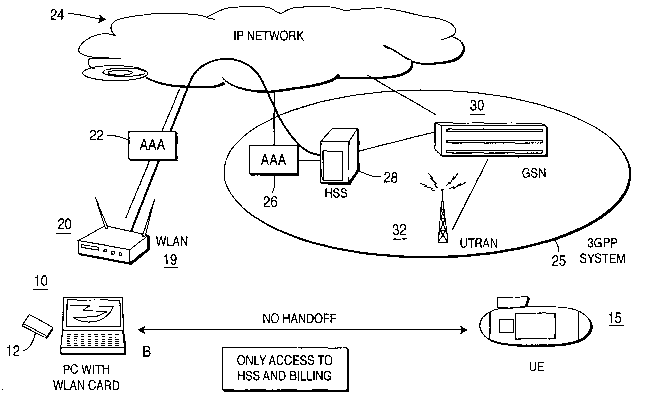
reference to the drawings, Figure 1 represents the present state of the art
wherein a personal computer (PC) 10 having a WLAN card 12 is capable of
communicating with an access point (AP) 20 of a WLAN 19. The WLAN has only
limited access to the 3rd generation partnership project (3GPP) system. The PC
communicates with an Internet protocol (IP) network 24 to send and receive
messages. However, PC 10 has access to the 3GPP system 25 only for
authentication and billing through the AAA function 22 of the WLAN AP 20, the
_A_A_A function 26 of UTRAN 25 and the HSS 28. There is no capability of a
_8_
CA 02497533 2005-03-02
WO 2004/023249 PCT/US2003/027506
handoff as between PC 10 and a wireless user equipment (UE) 15. The capability
shown in Fig. 1 shows inter-working in accordance with approved Scenario 2.
Although Figure 1 shows the PC10 and a user equipment 15 as separate entities,
it should be understood that they may be logical entities contained with a
common housing (not shown).
[0023] Figure 2 shows an interworking employing a new approach to
Scenario 3, which differs from the arrangement shown in Figure 2 with the
addition of instant messaging system IMS 34. Scenario 3 provides access to
packet switching (PS) service via the serving GSN (SGSN) forming part of GSN
30 in 3GPP system 25 in scenario 3. PC 10, in addition to having access to HSS
23 for authentication and billing, is further capable of obtaining instant
message
system (IMS) services through IP network 24, utilizing IMS 34. Nevertheless,
there is no handoff capability between PC 10 and UE 15.
[0024] Figure 3 shows an arrangement in which a handoff is achieved
without any changes in the WLAN 20. PC 10 is shown conducting a data session
between WLAN 20 and supporting service center (SC) 36 through IP network 24.
The data session connection is transferred to UE 15 operating wirelessly over
the UMTS network of the 3 GPP system 25 over tower 32.
[0025] Figure 4 is a flow diagram showing available handofF procedures.
[0026] A handoff procedure is triggered (see step S1) and may either be
user- initiated or performance-initiated. Given a user-initiated handoff (S2)
the
initiation may be solicited by the network (branching to S3) wherein the
network
informs the user that the network, for example, a WLAN, is available. In the
case of an unsolicited handoff trigger, the user may initiate the handoff (HO)
on
his own. In either the solicited (S3) or unsolicited (S4) handoff trigger, the
handoff is immediate.
[0027] An HO may be performance-initiated (branching from S1 to S5)
wherein initiation may be based upon a power measurement (branching to S6).
However, WLANs do not presently support a performance-initiated HO based on
power measurement.
-4-
CA 02497533 2005-03-02
WO 2004/023249 PCT/US2003/027506
[0028] An HO may be initiated based on frame error rate (FER) branching
from S5 to S7. However, a physical layer FER (PHY FER) is not supported by a
WLAN. A medium access control FER (MAC FER) may not be supported by a
WLAN and results in a slow procedure.
[0029] An Internet protocol FER (IP FER) results in a very slow handoff
and it should further be noted that the Internet protocol (IP) does not have
cyclic
redundancy check (CRC).
[0030] Figure 5 is a flow diagram showing a generalized HO scenario
employing target home location register/home subscriber server (HLR/HSS)
access. At step S11 an HO is initiated when a subscriber, which may, for
example, be a PC equipped with a WLAN card, decides to transfer a current
session from one system, A, which may, for example, be a WLAN, to a second
system, B, which may, for example, be a universal mobile telecommunications
system (UMTS). Upon making this decision, the subscriber operates a handoff
button B provided as part of the subscriber unit, such as PC 10 shown in
Figure
3. Responsive to operation of the HO button, the subscriber is presented with
a
list of option target systems such as, for example, WLAN, CDMA 2000, UMTS,
etc. (S13).
[0031] The routine advances to S14 at which time a determination is made
as to whether there are any connections between terminals, such as PC 10 and
UE 15 shown in Fig. 3. If there is a connection, the routine branches to S15
to
initiate a confirmation process ensuring the connectivity of the other
terminal,
for example a UMTS.
[0032] In the event that there is no connection between terminals, the
routine branches from S14 to S16 which asks the subscriber to confirm that the
other terminal, for example, the terminal in the UMTS system is on and is
connected with system B. The routine then advances to S17 to inquire if system
A, such as for example a WLAN, has any information regarding the target
triplet
which includes the ID of system B, the ID of the terminal communicating with
system B and the IP address. In the event that system A does not have the
_5_
CA 02497533 2005-03-02
WO 2004/023249 PCT/US2003/027506
target triplet information, the subscriber is requested to provide the target
information.
[0033] In the case where system A has the target information, the routine
branches to S19 to retrieve the necessary information about the connections to
the target system, i.e. system B. As is described above, the retrieved
information
is obtained either from system A or from the subscriber. The routine then
advances to S20 wherein the target system data base, for example, the HLR/HSS,
is contacted for information retrieval, verification and authorization. When
the
necessary criteria is present, the routine branches to S21 wherein system A
initializes the service at the target system B and informs the service
provider,
i.e., the session partner to reroute the session traffic to system B. In the
event
the current session is the only running session in system A, an inquiry may be
made to the subscriber to determine if the subscriber would like to terminate
the
connection to the system A or to continue operation.
[0034] Figure 6 shows a generalized HO scenario in which a target
HLRJHSS is omitted. For purposes of simplicity, only those steps which are not
shown in Figure 5 will be described in detail.
[0035] Steps S11 through S17 are substantially identical to the
corresponding steps S 11 through S 17 shown in Fig. 5. However, at step S 17,
in
the event that system A does not have the target triplet information, the
routine
branches to step S22 to obtain the target IP address information from the
subscriber.
[0036] Advancing from step 515, the necessary information regarding
connections to the target system are retrieved at 519, the target information
either being obtained from system A (S17) or from the target address
information
provided by the subscriber (S22). The routine then branches to S23 wherein the
target system may be contacted for information retrieval, verification and
authorization. Thereafter if the appropriate criteria are met, the routine
advances to step S21 which is substantially the same as corresponding step S21
in Fig. 5.
-6-
CA 02497533 2005-03-02
WO 2004/023249 PCT/US2003/027506
[0037] Figure 7 shows an HO scenario from a WLAN to a UMTS. Steps
S11 and S12 are substantially identical to the corresponding initial steps S11
and
S12 of Figures 5 and 6. Upon operation of the HO initiation button, the
routine
advances to step 527, providing a window to the subscriber inviting the
subscriber to select the target system from among the choices displayed and to
further ensure that the terniixial intended to communicate with the target
system
is on and connected. The routine then advances to step S28 which is
substantially identical to step S17 shown in the routines of Figs. 5 and 6
wherein
an inquiry is made as to whether the WLAN has information regarding the
target triplet. In the event that the UMTS does not have target triplet
information, the routine branches to step S29 in order to obtain the system
and/or terminal information from the subscriber. Returning to step 528, the
routine looping here until the requested information is obtained. Although not
shown, the routine may be exited in the event that the requested information
is
not obtained after a given number of tries, for example, three (3) tries.
However,
a lesser or greater number of tries may be programmed before aborting.
[0038] When the triplet information is obtained, the routine branches to
step S30 whereupon the HLR/HSS of the target system is contacted. The routine
advances to step S31 to determine if the terminal is on. In the event that the
terminal is on, the routine branches to step S33 to determine if the packet
data
protocol (PDP) is active. In the event that the PDP is not active, the routine
branches to step S34 to activate the PDP context and thereafter obtain the IP
address (S35), followed by performing the re-routing process (S36).
[0039] Returning to 533, in the event that the PDP is active, the IP address
is obtained (S35) and the rerouting process is performed (S36).
[0040] Returning to 531, if the terminal is not on, the routine branches to
S32 requesting the subscriber to switch on and confirm. The routine advances
to
S3'7 to determine if the confirmation has been received. If the confirmation
has
been received, the routine branches to S39 wherein a predetermined delay is
provided before the target system is contacted (S30).
_7_
CA 02497533 2005-03-02
WO 2004/023249 PCT/US2003/027506
[0041] In the event that a confirmation is not received, the routine
branches to S38 and the HO is aborted.
[0042] Figure 8 shows an HO scenario from a UMTS to a WLAN which
utilizes interworking.
[0043] As the HO routine is initiated when the subscriber makes a decision
to transfer a current session from UMTS from WLAN (S40) and thereafter
triggers the HO procedure button during the current UMTS session (S41),
whereupon the subscriber is invited to select the target system from a display
provided to the subscriber and is further alerted to assure that the terminal
to be
connected to the WLAN, for example, a PC with a WLAN card, is on and
connected to the WLAN.
[0044] Thereafter, an inquiry is made as to whether the UMTS has the
target triplet information. In the event that the UMTS does not have the
target
information, the routine branches to S44 to obtain the system terminal and/or
TP
information from the subscriber, looping back to 543. When the target
information is available, the routine branches to S45 whereupon the HSS in the
UMTS is contacted. The routine then advances to S46 to determine if the WLAN
terminal is on. In the event the WLAN terminal is off, the routine branches to
S47 requesting the subscriber to activate the WLAN terminal and confirm
activation. It should be noted that step S47 is substantially identical to
corresponding step S32 shown in Fig. 7 and the identity of these steps is
shown
by placing "(S32)" adjacent to step 547. Steps S48 through S50 operate in
substantially the same manner as steps S37 through S39 of Fig. 7 and are shown
with the associated equivalent step number of Fig. 7 in parenthesis. Reference
to
performance to steps S48 to S50 should therefore be made to the description of
steps S37 through S39 set forth above.
[0045] Making reference to step 550, the HSS in the UMTS is contacted
after a predetermined interval (S45) responsive to completion of step 550.
[0046] When the WLAN terminal is identified as being on (S46) the target
IP address is obtained (S51) and the rerouting process is performed (S52).
_g_
CA 02497533 2005-03-02
WO 2004/023249 PCT/US2003/027506
[0047] Figure 9 shows the scenario for HO from UMTS to WLAN without
interworking. Making reference to Figure 9, steps S40 through S43 are
substantially identical to corresponding steps S40 through S43 shown in Figure
8
and reference should be made to the description of these corresponding steps
as
set forth above.
[0048] In the event that the UMTS does not have the target information,
the program branches to step S44 which is substantially similar to
corresponding
step 44 in Fig. 8 and the description thereof is set forth above.
[0049] Once the target information is obtained, the routine branches to S53
to extract the target IP address. The existence of the IP address is checked
at
step 554. If the confirmation is positive (S55), the rerouting process is
performed
(S56). In the event that confirmation has not been received, the routine
branches
to S57 to instruct the subscriber to turn the terminal on and provide
information
that these steps have been performed. At step 558, once the confirmation is
received, the routine then branches to S59 and the routine returns to 543.
Steps
S43 through S55 are again repeated and in the event that confirmation is not
received (S55), and this is the second inquiry, the routine branches at S57 A
whereupon the HO effort is aborted (S60).
_g_