Note : Les descriptions sont présentées dans la langue officielle dans laquelle elles ont été soumises.
CA 02497732 2008-05-07
52586-1D
MAGNETORHEOLOGICAL FLUID
This application is a divisional of Canadian
Patent Application Serial No. 2,163,671 filed June 3, 1994.
FIELD OF THE INVENTION
This invention relates to methods of polishing
surfaces using magnetorheological fluids.
BACKGROUND OF THE INVENTION
Workpieces such as glass optical lenses,
semiconductors, tubes, and ceramics have been polished in
the art using one-piece polishing tools made. of resin,
rubber, polyurethane or other solid materials. The working
surface of the polishing tool should conform to the
workpiece surface. This makes polishing complex surfaces
complicated, and difficult to adapt to large-scale
production. Additionally, heat transfer from such a solid
polishing tool is generally poor, and can result in
superheated and deformed workpieces and polishing tools,
thus causing damage to the geometry of the workpiece surface
and/or the tool.
CA 02497732 2009-10-20
52586-1D
2
SUMMARY OF THE INVENTION
Improved devices and methods for polishing objects
in a magnetorheological polishing fluid (MP-fluid) are
provided. More particularly, a highly accurate method of
polishing objects, in a magnetorheological fluid, which may
be automatically controlled is provided, as are improved
polishing devices. The method comprises the steps of
creating a polishing zone within a magnetorheological fluid;
bringing an object to be polished into contact with the
polishing zone of the fluid; determining the rate of removal
of material from the surface of the object to be polished;
calculating the operating parameters, such as magnetic field
intensity, dwell time, and spindle velocity, for optimal
polishing efficiency; and moving at least one of said object
and said fluid with respect to the other according to the
operating parameters.
The polishing device comprises an object to be
polished, a magnetorheological fluid, which may or may not
be contained within a vessel, a means for inducing a
magnetic field, and a means for moving at least one of these
components with respect to one or more of the other
components. The object to be polished is brought into
contact with the magnetorheological fluid and the
magnetorheological fluid, the means for inducing a magnetic
field, and/or the object to be polished are put into motion,
thereby allowing all facets of the object to be exposed to
the magnetorheological fluid.
In the method and devices, the magnetorheological
fluid is acted upon by a magnetic field in the region where
the fluid contacts the object to be polished. The magnetic
field causes the MP-fluid to acquire the characteristics of
a plasticized solid whose yield point depends on the
magnetic field intensity and the viscosity. The yield point
CA 02497732 2010-07-08
52586-1D
3
of the fluid is high enough that it forms an effective
polishing surface, yet still permits movement of abrasive
particles. The effective viscosity and elasticity of the
magnetorheological fluid when acted upon by the magnetic
field provides resistance to the abrasive particles such
that the particles have sufficient force to abrade the
workpiece.
One broad aspect of the present invention may be
summarized as a magnetorheological fluid for finishing
workpiece surfaces, comprising: soft magnetic particles;
abrasive particles; a stabilizer; and a carrying fluid,
wherein the soft magnetic particles are coated with an
oxidation inhibiting polymer and wherein the carrying fluid
comprises water.
BRIEF DESCRIPTION OF THE DRAWINGS
Figure 1 is a cross-sectional side view of a
polishing device of an embodiment of the invention.
Figure 2 is a cross-sectional side view of another
embodiment of the invention.
Figure 3 is a cross-sectional side view of another
embodiment of the invention.
Figure 4 is a graph showing the amount of material
removed, as a function of distance from the center of the
workpiece, for an exemplary workpiece.
Figure 5, appearing on drawing sheet 16 together
with Figure 22, is a schematic diagram illustrating the
parameters used in the method of an embodiment of the
invention to control polishing for a flat workpiece.
CA 02497732 2010-07-08
52586-1D
3a
Figure 6 is a schematic diagram illustrating the
parameters used in the method of the invention to control
polishing for a curved workpiece.
Figure 7 is a graph showing the relationship
between the rate of material removal during polishing and
the magnetic field intensity.
Figure 8 is a graph showing the relationship
between the rate of material removal during polishing and
the clearance between a workpiece and the bottom of a vessel
in which the workpiece is polished.
Figure 9 is a cross-sectional side view of another
embodiment of the invention.
Figure 10 is a cross-sectional side view of
another embodiment of the invention.
Figure 11 is a cross-sectional side view of
another embodiment of the invention.
Figure 12 is a cross-sectional side view of
another embodiment of the invention.
CA 02497732 1994-06-03
61293-357D
4
Figure 13 is a cross-sectional side view of
another embodiment of the invention.
Figure 14 is a cross-sectional side view of
another embodiment of the invention.
Figure 15 is a cross-sectional side view of
another embodiment of the invention.
Figure 16 is a cross-sectional side view of
another embodiment of the invention.
Figure 17 is a cross-sectional side view of
another embodiment of the invention.
Figure 18 is a cross-sectional side view of
another embodiment of the invention.
Figure 19 is a cross-sectional side view of
another embodiment of the invention.
Figure 20 is a cross-sectional side view of
another embodiment of the invention.
Figure 21 is a cross-sectional side view of
another embodiment of the invention.
Figure 22 is a cross-sectional side view of
another embodiment of the invention.
Figure 23 is a cross-sectional side view of
another embodiment of the invention.
Figure 24 is a cross-sectional side view of
another embodiment of the invention.
Figure 25 is a cross-sectional side view of
another embodiment of the invention.
Figure 26 is a cross-sectional side view of
another embodiment of the invention.
Figure 27 is a cross-sectional side view of
another embodiment of the invention.
Figure 28 is a cross-sectional side view of
another embodiment of the invention.
Figure 29 is a cross-sectional side view of
another embodiment of the invention.
Figure 30 is a cross-sectional side view of
another embodiment of the invention.
CA 02497732 1994-06-03
61293-357D
DETAILED DESCRIPTION OF THE PREFERRED EMBODIMENTS
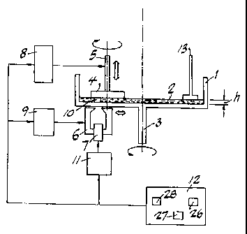
Figure 1 is a schematic of a polishing device
which may be operated according to the method of the
5 present invention. In Fig. 1, a cylindrical vessel 1
contains magnetorheological polishing fluid (MP-fluid) 2.
In a preferred embodiment, the MP-fluid 2 contains an
abrasive. Vessel 1 is preferably constructed of a non-
magnetic material which is inert to the MP-fluid 2. In
Figure 1, vessel 1 is semi-cylindrically shaped in cross-
section and has a flat bottom. However, the particular
shape of vessel 1 may be modified to suit the workpiece
to be polished, as will be described in greater detail.
An instrument 13, such as a blade, is mounted
into vessel 1 to provide continuous stirring of the MP-
fluid 2 during polishing. A workpiece 4 to be polished
is connected to a rotatable workpiece spindle 5.
Workpiece spindle 5 is preferably made from a non-
magnetic material. Workpiece spindle 5 is mounted on a
spindle slide 8, and can be moved in the vertical
direction. Spindle side 8 may be driven by a
conventional servomotor which operates according to
electrical signals from a programmable control system 12.
Rotation of vessel 1 is controlled by vessel
spindle 3, which is preferably positioned in a central
location below vessel 1. Vessel spindle 3 can be driven
by conventional motor or other power source.
An electromagnet 6 is positioned adjacent to
vessel 1 so as to be capable of influencing the MP-fluid
2 in a region containing the workpiece 4. Electromagnet
6 should be capable of inducing a magnetic field
sufficient to carry out the polishing operation, and
preferably will induce a magnetic field of at least about
100 kA/m. Electromagnet 6 is activated by winding,7 from
power supply unit 11 which is connected to control system
12. Winding 7 can be any conventional magnetic winding.
Electromagnet 6 is set up on an electromagnet slide 9 and
CA 02497732 1994-06-03
61293-357D
6
can be moved in a horizontal direction, preferably along the
radius of vessel 1. Electromagnet slide 9 may be driven by
a conventional servoraotor which operates according to
electrical signals from the programmable control system 12.
Winding 7 is activated by power supply unit 11
during polishing to induce a magnetic field and influence
the MP-fluid 2. Preferably, MP-fluid 2 is acted on by a
none-uniform magnetic; field in a region adjacent to the
workpiece 4. In this preferred embodiment, equal-intensity
lines of the field are normal, or perpendicular, to the
gradient of said field, and the force of the magnetic field
is a gradient directed toward the vessel bottom normal to
the surface of workpiece 4. Application of the magnetic
field from electromagnet 6 causes the MP-fluid 2 to change
its viscosity and plasticity in a limited polishing zone 10
adjacent to the surface being polished. The size of the
polishing zone 10 is defined by the gap between the pole-
pieces of the electromagnet 6 and the shape of the tips of
the electromagnet 6. Abrasive particles in the MP-fluid are
preferably acted upon by the MP-fluid substantially only in
polishing zone 10, and the pressure of MP-fluid against the
surface of workpiece 4 is largest in the polishing zone 10.
The composition of the MP-fluid 2 used in the
method and devices discussed herein may take different
forms. In a preferred embodiment, an MP-fluid comprising a
plurality of magnetic particles, a stabilizer, and a
carrying fluid selected from the group consisting of water
and glycerin, is used.. In a further preferred embodiment,
the magnetic particles (preferably
CA 02497732 2008-05-07
52586-1D
7
carbonyl iron particles) are coated with a protective
layer of a polymer material which inhibits their
oxidation. The protective layer is preferably resistent
to mechanical stresses, and as thin as practicable. In a
preferred embodiment, the coating material is TeflonTM.
The particles may be coated by the usual process of
mi crocapsulation .
The polishing machine shown in Figure 1 can
operate as follows. Workpiece 4 is coupled to workpiece
spindle 5, and positioned by spindle slide 8 at a
clearance, h, with respect to the bottom of vessel 1 so
that preferably a portion of the workpiece 4 to be
polished is immersed in the MP-fluid 2. Said clearance h
may be any suitable clearance which will permit polishing
of the workpiece. The clearance h will affect the
-material removal rate V for the workpiece 4, as
illustrated.i.n Figure 8,.and will also affect the size of
a contact spot RZ at which the polishing zone 10 contacts
the workpiece 4. The clearanceh is preferably chosen so
that the surface area of the contact spot RZ is less than
one third of the surface area of the workpiece 4. The
clearance h may be changed during the polishing process.
In a preferred embodiment, both workpiece 4 and
vessel 1 are rotated, preferably counter to each other.
Vessel spindle 3 is put into rotating motion, thereby
rotating vessel 1. Vessel spindle 3 rotates about a
central axis and preferably rotates vessel 1 at a speed
sufficient to effect polishing but insufficient to
generate a centrifugal force sufficient to substantially
eject or spray MP-fluid 2 ,out of vessel 1. In a
preferred embodiment,, the vessel is rotated at a constant
velocity. The motion of vessel 1 provides continuous
delivery of a fresh portion of MP-fluid 2 to the region
where workpiece 4 is located, and provides continuous
motion of the MP-fluid 2 in contact with the surface of
the workpiece being polished in the polishing zone'10.
In a preferred embodiment additional carrying fluid,
CA 02497732 1994-06-03
61293-357D
8
preferably water or glycerin, is added during polishing
to replenish carrying fluid that has vaporized, and thus
maintain the properties of the fluid.
Workpiece spindle 5 is also rotated, about a
central axis, to provide rotating movement to workpiece
4. In a preferred embodiment, workpiece spindle 5
operates at speeds of up to 2000 rpm, with about 500 rpm
particularly preferred. The motion of workpiece spindle 5
continuously brings a fresh part of the surface of the
workpiece 4 into contact with the polishing zone 10, so
that material removal along the circumference of the
surface being polished will be substantially uniform.
As abrasive particles in the MP-fluid 2 contact
the workpiece 4, a ring-shaped area having a width of the
polishing zone is gradually polished on to the surface of
the workpiece 4. Polishing is accomplished in one or
more cycles, with an incremental amount of material
removed from the workpiece in each cycle. Polishing of
the whole surface of the workpiece 4 is achieved by
radial displacement of the electromagnet 6 using
electromagnet slide 9, which causes the polishing zone 10
to move relative to the workpiece surface.
The radial motion of the electromagnet 6 may be
continuous, or in discrete steps. If the movement of the
electromagnet 6 is continuous, the optimal velocity UZ of
electromagnet 6 for each point of the trajectory of
motion is calculated. The velocity of the electromagnet,
UZ, can be calculated according to the following formulae:
(I) UZ = 2RZ/t
or
(III/ Uz s 2RZV/k3
wherein RZ is the radius of the contact spot, in mm, in
the polishing zone 10 which contacts the workpiece 4, t
is the time, in seconds, for which the contact spot RZ is
polished during one cycle, V is the material removal
rate, in m/min, and k: is the thickness, in gum, of the
workpiece material layer to be removed during one cycle
CA 02497732 1994-06-03
61293-357D
9
of polishing.
RZ is a function of the clearance h, as
described above. The material removal rate, V, can be
empirically determined given the clearance h and the
velocity at which the vessel 1 is rotated. The material
removal rate V may be determined by measuring the amount
of material removed from a given spot in a given time.
The thickness of the workpiece material layer to be
removed during one polishing cycle, k3, is a function of
the accuracy required for the finished workpiece; k3 may
be selected to minimize local error accumulation. For
example, when optical glass is polished, the value of k3
is determined by the required fit to shape in waves. The
amount of time for which the contact spot RZ should be
polished during one cycle, t, is calculated according to
the formula:
t s k3/V
When k3 and the velocity of the magnet. Uz, have
been determined, the number of cycles required and the
time required for polishing may be determined. To
calculate the total number of cycles, N, to polish the
workpiece 4, the thickness of the layer of material to be
removed during polishing, K. is calculated according to
the formula:
K = k, + k2
where k, is the initial surface roughness in m, and k, is
the thickness of the subsurface damage layer in m. The
number of cycles required, N, may then be determined
using the formula:
N = K/k3
The amount of time required for one cycle, t,,
may be calculated using the following formula:
t, = R./U,
where Ra, is the radius of the workpiece. Figure 5 shows
the relationship of the radius of the workpiece P.,,, the
contact spot RZ, the clearance h, and the velocity of the
magnet U, for a flat workpiece such as is shown in
CA 02497732 1994-06-03
61293-357D
Figure 1.
The total time T required for polishing may be
calculated using the formula:
T = NR.W/UZ
5 where N is the number of cycles required, R,. is the
radius of the workpiece, and UZ is the velocity of the
electromagnet 6.
If the electromagnet 6 is moved in discrete
steps, the dwell time at each step must be determined.
10 In a preferred embodiment, the overall material removal
is maintained constant at each step. To remove a
constant amount of material during stepwise polishing, it
is necessary to take into account material removal due to
overlapping of the contact spots RZ at successive steps.
The coefficient of overlapping, I, is determined by the
formula:
I = r/2RZ
where r is the displacement of the workpiece in a single
step, in mm, and RZ is the radius of the contact spot.
The displacement in a single step, r, may be determined
empirically using results from preliminary trials, such
as those detailed in the example given below.
The dwell time for each step in a given cycle, td,
may be determined according to the formula:
Cd = k3I/V
where k3 is the thickness of the workpiece material layer
to be removed during one polishing cycle, I is the
coefficient of overlapping, and V is the material removal
rate for the workpiece at a given clearance h and a given
velocity of the vessel 1.
The number of steps in one cycle, nõ for
stepwise polishing may be determined using the formula:
n,=Rw/r
where R, is the radius of the workpiece, and r is the
displacement of the workpiece in a single step. The
total number of cycles, N, required to polish the
workpiece may be calculated using the formula used with
CA 02497732 1994-06-03
61293-357D
11
continuous polishing, that is:
N = K/k3
where K is the thickness of the layer of material to be
removed during polishing, and k3 is the thickness of the
workpiece material layer to be removed during one
polishing cycle. The total time required for stepwise
polishing, T, may be calculated using the formula:
T = tdn,N
where td is the dwell time for each step, n, is the number
of steps in one cycle, and N is the total number of
cycles.
In a preferred embodiment of the invention, a
computer program for control unit 12 may be prepared on
the basis of these calculations, for either continuous or
stepwise polishing. The whole process of polishing a
workpiece 4 may then be conducted under automatic
control. As shown in Figure 1, the control unit 12
preferably includes an input device 26, a processing unit
27, and a signal generator 28.
in an alternate embodiment of the invention,
the accuracy of figure generation, or correspondence of
the finished workpiece to the desired shape and
tolerances, may be improved by conducting tests to
determine the spatial distribution of the removal rate of
the material as a function of R2, V [RZ] , in the contact
spot R. The spatial distribution of the removal rate may
be determined by the method of successive approximation,
as detailed in the example given below and in Figure 4.
The spatial distribution of the removal rate may then be
used to more accurately determine the parameters of the
polishing program, such as the dwell time, td, using the
formulas previously discussed. In this case, the dwell
time can be determined using the formula:
td - k3I/V [RZ]
Referring to Figure 2, there is shown an
alternate embodiment of the invention. This embodiment
achieves highly efficient polishing of convex workpieces
CA 02497732 1994-06-03
61293-357D
12
204, such as spherical and nonspherical optical lenses.
In Figure 2, the vessel 201 is a circular trough, and the
radius of curvature of the internal wall, adjacent to
polishing zone 210, is larger than the largest radius of
curvature of workpiece 204. During polishing, it is
desirable to minimize the movement of the fluid 202
relative to the vessel 201. To minimize this movement,
or slippage, of the MP-fluid 202, the internal wall of
the vessel 201 may be covered with a layer of a nap, or
porous, material 215 to provide reliable mechanical
adhesion between the MP-fluid 202 and the wall of the
vessel 201.
Workpiece spindle 205 is connected with spindle
slide 208, which is connected with a rotatable table 216.
The rotatable table 216 is connected to a table slide
217. Spindle slide 208, rotatable table 216, and table
slide 217 may be driven by conventional servomotors which
operate according to electrical signals from programmable
control system 212. Rotatable table 216 permits
workpiece spindle 205 to be continuously rocked about its
horizontal axis 214, or permits its positioning at an
angle cY with the initial vertical axis 218 of spindle
205. Axis 21.4 preferably is located at the center of
curvature of the polished surface at the initial vertical
position of the workpiece spindle. Spindle slide 208
permits vertical displacement b of the center of polished
surface curvature relative to axis 214. Table slide 217
moves the rotatable table 216 with spindle slide 208 and
workpiece spindle 205 to obtain, and maintain, the
desired clearance h between the polished surface of
workpiece 204 and the bottom of vessel 201. In this
embodiment, an electromagnet 206 is stationary, and is
positioned below the vessel 201 such that its magnetic
gap is symmetric about the workpiece spindle axis 218
when this axis is perpendicular to the plane of polishing
zone 210. The device illustrated in Figure 2 is the same
as the device shown in Figure 1 in all other respects.
CA 02497732 1994-06-03
61293-357D
13
The polishing machine operates as follows. To
polish workpiece 204, workpiece spindle 205 with attached
workpiece 204 is,positioned so that the center of the
radius of curvature of workpiece 204 is brought into
coincidence with the pivot point (axis of rotation 214)
of the rotatable table 216. The removal rate for the
workpiece to be polished is then determined
experimentally, using a test workpiece similar to the
workpiece to be polished. Polishing of work piece 204
may then be conducted automatically by moving its surface
relative to polishing zone 210 using rotatable table 216,
which rocks workpiece spindle 205 and changes the angle a
according to calculated regimes of treatment.
The maximal angle a to which the spindle 205
may be rocked is determined using the formula:
cos a.. = (R,f - L) /Rf
where R,f is the radius of the total sphere. As shown in
Figure 6, R,f represents what the radius of the workpiece
would be if it were spherical, based upon the radius of
curvature of the actual workpiece 204. L represents the
thickness of the workpiece 204, as indicated on Figure 6,
and it may be calculated using the formula:
L = R.f - RZ.f - R".=
The angle dimension of the contact spot,
also indicated on Figure 6, may be determined using the
formula:
cos j3 = (R,f -ho) /R,f
where R,f is the radius of the total sphere and ho is the
clearance between the bottom of the vessel 201 and the
edge of the contact spot RZ for a curved workpiece, as
shown in Figure 6. The height of the contact spot, ho,
may be determined using the formula:
ho = Rsf - R2.f - R2
where R,f is the radius of the total sphere and R, is the
width of the contact spot.
Rocking of workpiece spindle 205 may be
continuous or stepwise. If the workpiece spindle 205 is
CA 02497732 1994-06-03
61293-357D
14
continuously rocked, the angular velocity w, of this
motion is determined by the formula:
WZ a QV/k3
where # is the angle dimension of the contact spot, V is
the material removal rate, and k3 is the thickness of the
workpiece material layer to be removed during one cycle
of polishing. The duration of one cycle, t., may then be
calculated using the formula
ctmulcoz
where a. is the maximal angle cY to which the spindle 205
may be rocked, and w, is the angular velocity of the
rocking motion.
To calculate the total number of cycles, N, to
polish the workpiece 204. the thickness of the layer of
material to be removed during polishing, K. is calculated
according to the formula
K=k,+k2
where k, is the initial surface roughness in Am, and k2 is
the thickness of the subsurface damage layer in Am. The
number of cycles required, N, may then be determined
using the formula
N = K/k3
where k3 is the thickness of the workpiece material layer
to be removed during one cycle of polishing.
The total time T required to polish the
workpiece may then be calculated using the formula
T = t,N
where t, is the duration of one cycle, and N is the number
of cycles required.
If the workpiece spindle 205 is rocked in
discrete steps, the dwell time for each step must be
calculated. In calculating the dwell time for each step,
it is necessary to take the coefficient of overlapping I
into account. The coefficient of overlapping I is
determined by the formula
I = a,/a
where is the angle dimension of the contact spot, and a,
CA 02497732 1994-06-03
61293-357D
is the angle displacement for one step. The angle
displacement for one step, a,, may be calculated by the
formula:
a,=am,x/n:
5 where a,,,,x is the maximal angle a to which the spindle 205
may be rocked, and n, is the number of steps in one cycle.
The number of steps per cycle, n,, may be calculated using
the formula
n.=a./$
10 where a,,. is the maximal angle a to which the spindle 205
may be rocked, and # is the angle dimension of the
contact spot. The current angle a during polishing may
be calculated using the formula:
a = aN,
15 where a, is the angle displacement for one step, and N, is
the number of the current step.
To calculate the total number of cycles, N, to
polish the workpiece 204, the thickness of the layer of
material to be removed during polishing, K, is calculated
according to the formula:
K = k, + k2
where k, is the initial surface roughness in m, and k, is
the thickness of the subsurface damage layer in zm. The
number of cycles required, N, may then be determined
using the formula:
N = K/k3
where k3 is the thickness of the workpiece material layer
to be removed during one cycle of polishing.
The dwell time at each step may be calculated
using the formula:
td = k3I/V
where k3 is the thickness of the workpiece material layer
to be removed during one cycle of polishing, I is the
coefficient of overlapping, and V is the material removal
rate. The total time T required to polish the workpiece
may then be calculated using the formula:
T = tdnN
CA 02497732 1994-06-03
61293-357D
16
where td is the dwell time for each step, n, is the number
of steps per cycle, and N is the number of cycles
required.
The polishing may be conducted under conditions
which yield uniform material removal from each point of
the surface, if it is desired that the surface figure
should not be altered, or specific material removal goals
for each point on the surface may be achieved by varying
the dwell time.
When a non-spherical workpiece 204 is to be
polished, the procedure is generally the same as
described for a spherical workpiece. A non-spherical
workpiece 204 may be polished to the desired shape by
varying the dwell time depending upon the radius of
curvature of the section of the workpiece being polished.
In an alternate embodiment for polishing a non-spherical
workpiece, workpiece spindle 205 may also be moved
vertically during polishing. To polish a non-spherical
object, the calculations previously described may be
carried out for each section of the workpiece having a
different radius of curvature. As it is rocked to angle
a, the radius of curvature of the section of a non-
spherical workpiece being polished changes. To bring the
momentary radius of curvature for the section of the
workpiece 204 being polished into coincidence with pivot
point 214, rocking of the workpiece spindle 205 is
accompanied with vertical motion by spindle slide 208
when polishing non-spherical objects.
The magnetic field strength may also be varied
for each stage of treatment during polishing, if desired.
The material removal rate V is a function of the magnetic
field intensity G, as shown in Figure 7. It is therefore
possible to change the quantities of the operating
parameters, such as dwell time or clearance. Thus the
magnetic field strength may be used as another means for
controlling the polishing process.
Referring to Figure 3, there is shown an
CA 02497732 2008-05-07
52586-1D
17
alternate embodiment of the invention. In Figure 3, the
internal wall of the vessel 301 has an additional
circular trough which passes through the gap of the
electromagnet 306. This configuration of the internal
wall of the vessel 301 results in a smaller, more
focused, polishing zone 310, and an increase in adhesion
between the MP-fluid 302 and the vessel 301 is achieved.
The smaller, more focused, polishing zone will result in
a smaller contact spot R2. In all other respects the
embodiment depicted in Figure 3 is the same as that
depicted in Figure 2.
Exanrole 1
The polishing of a glass lens was accomplished,
using a device as shown in Figure 2. The workpiece 204
had the following initial parameters:
a) Glass type 5E7
b) Shape . . . . . . . . . . . . . . . . Spherical
c) Diameter, mm 20
d) Radius of curvature, mm . . . . . . . . . . 40
e) Center thickness, mm 15
f) Initial fit to shape, waves . . . . . . . 0.5
g) Initial surface roughness, nm, rms . . . . 100
A vessel 201, in which the radius of curvature
of the internal wall adjacent to the electromagnet pole
pieces 206 was 200 mm, was used. The radius from central
axis 219 was 145 mm and the width of the vessel trough
was 60 mm. The vessel 201 was filled with 300 ml of the
MP-fluid 202., having the following composition:
Component Weight Percentage
Polirit (cerium oxide) 10
Carbonyl iron powder 60
AerosilTM (fumed silica) 2.5
Glycerin 5.5
Distilled water balance
To determine the material removal rate, a test
workpiece 204 identical to the workpiece to be polished
was polished at arbitrarily chosen standard parameters.
CA 02497732 1994-06-03
61293-357D
18
The test workpiece was attached to the workpiece spindle
205 and positioned by spindle slide 208 so that the
distance between the workpiece surface to be polished and
the pivot point of the rotatable table 216 (axis 214) was
equal to 40 mm (the radius of curvature of the workpiece
204 surface). Using rotatable table 216, the axis of
rotation of workpiece spindle 205 was set up in a
vertical position where angle opt = 00. The clearance h
between the surface of workpiece 204 to be polished and
the bottom of the vessel 201 was set at 2 mm using the
table slide 217.
Both the workpiece spindle 205 and the vessel
201 were then rotated. The workpiece spindle rotation
speed was 500 rpm, and the vessel rotation speed was 150
rpm. The electromagnet 206, having a magnet gap equal to
mm, was turned on to a level where the magnetic field
intensity near the workpiece surface was about 350 kA/m.
All parameters were kept constant, and the workpiece was
polished for about 10 minutes, which was sufficient to
20 create a well-defined spot.
Next, the workpiece was removed from the
workpiece spindle 205. Using a suitable optical
microscope, measurements were then conducted to determine
the amount of material H (in m) removed from the
original surface as a function of distance R (in mm) away
from the center of the workpiece. In the example
described here, a Chapman Instrument MP2000 optical
profiler was used to measure the amount of material
removed. Depending on the metrology available, about 20
measurements are made over a 20 mm distance. In this
example, 16 measurements were made over 19.7 mm. The
results of these measurements for this example are
plotted in Figure 4. These results define the polishing
zone for the machine set-up, and they are used as input
for calculating the polishing program required to finish
the workpiece. The inputs obtained in this example for
calculating the polishing program are as follows:
CA 02497732 1994-06-03
61293-357D
19
1. Parameters of the workpiece:
a) radius of the total sphere, RSf, mm 39.6
b) radius of workpiece, R., mm . . . . 24.3
2. Parameters of the polishing zone:
a) radius of the contact spot, R2, mm 17.9
b) radius of the point where
(d/dr)(dH/dr) = 0, Rd, mm . . . . . . 10
c) maximum of H, Hu, m . . . . . . . 21.5
d) minimum of H, Ham, m . . . . . . . . 0.5
3. Spatial distribution of removed material in the
polishing zone:
R, mm H, m
0.0 15.2
3.3 19.5
5.1 21.5
6.4 20.9
7.5 19.2
8.9 16.8
10.8 11.9
12.4 9.8
13.8 6.7
15 5.1
16.2 3.8
17.2 3.0
18.2 1.9
18.6 1.3
19.3 1.3
19.7 0.5
Using these inputs, the polishing required to
finish the workpiece is determined. In a preferred
embodiment of the present invention, a computer program
is used to calculate the necessary parameters and control
the polishing operation. Determination of the polishing
requirements includes determination of the number of
steps for changing angle a, the value of angle a for each
step, and the dwell time for each step in order to
maintain constant: the material removal over the surface
CA 02497732 1994-06-03
61293-357D
of the workpiece by overlapping polishing zones, as
described above.
The parameters of the workpiece, parameters of
the polishing zone, and spatial distribution of removed
5 material in the polishing zone given above for this
example are used to control the system during the
polishing method. In this example, the results were
entered into a computer program for this purpose. The
results of the calculations were as follows:
10 Polishing regime
Table 1
Angle, a Time coefficient Control radiuses.
0.00 1.000 0.00
15 1.79 1.000 1.25
3.58 1.000 2.49
5.37 1.000 3.74
7.16 1.000 4.98
8.95 1.000 6.22
20 10.74 1.208 7.45
12.53 1.208 8.68
14.32 1.208 9.89
16.11 1.416 11.10
17.90 1.624 12.29
19.70 1.832 13.48
21.49 2.040 14.65
23.28 2.040 15.81
25.07 2.040 16.95
26.86 1.624 18.07
28.65 1.832 19.18
30.44 38.119 20.26
As used here, the control radius represents the relative
position of the polishing zone with respect to the
central vertical axis of the workpiece. The control
radius is determined by the angle a; during polishing it
is the angle a, rather than the control radius, that is
controlled.
CA 02497732 1994-06-03
61293-357D
21
The dwell times for each angle are then
converted to minutes by multiplying the time coefficients
in table 1 by a,constant factor. The constant factor
used to convert: the time coefficients to dwell times will
depend upon the characteristics of the workpiece. For
the example given here, this constant was empirically
determined to be 5 minutes.
Using the results from table 1, the
programmable controller 212 was programmed. The workpiece
204 to be polished was attached to the workpiece spindle
205, and the procedure described for the test workpiece
was repeated under the automatic control of the
programmable controller 212. The following results were
obtained.
Results of polishincr
Final fit to shape. waves . . . , . 1
Final roughness. m . . . . . 0.0011
In addition to the embodiments described above,
there are numerous alternate embodiments of the device of
the present invention. Some of these alternate
embodiments are shown in Figures 9 through 30. As
illustrated by these figures, only a magnetorheological
fluid, a means for inducing a magnetic field, and a means
for moving the object to be polished or the means for
inducing the magnetic field relative to one another are
required to construct a device according to the present
invention. For example, Figures 9 through 11 illustrate
an embodiment of the invention in which the
magnetorheological fluid is not contained within a
vessel.
In Figure 9, an MP-fluid 902 is placed at the
poles of an electromagnet 906. Electromagnet 906 is
positioned so that the magnetic field that it creates
acts only upon a particular surface section of the object
to be polished 904, thereby creating a polishing zone.
In operation, object 904 is put into rotation. Either
electromagnet 906, or object 904, or both electromagnet
CA 02497732 1994-06-03
61293-357D
22
906 and object 904, are then moved such that step-by-step
the entire surface of the object is polished.
Electromagnet 906, object to be polished 904, or both,
may be displaced relative to each other in the vertical
and/or horizontal planes. During polishing the magnetic
field strength is also regulated, as required, to polish
the object 904. Rotation of the object 904, movement of
the electromagnet 906 and/or the object 904, and
regulation of the magnetic field strength according to a
predetermined program of polishing permits controlled
removal of material from the surface of the object to be
polished 904.
Figure 10 illustrates a device for polishing
curved surfaces. In Figure 10, an MP-fluid 1002 is
placed at the poles of electromagnet 1006. The
electromagnet 1006 is configured such that it generates a
magnetic field affecting only some surface section of an
object to be polished 1004. Object to be polished 1004,
which has a spherical or aspherical surface, is put into
rotation. Electromagnet 1006 is displaced to an angle a
along the trajectory which corresponds to the radius of
curvature of the object 1004, as indicated by the arrows
in Figure 10, such that the electromagnet is moved
parallel to the surface of the object, according to a
predetermined program of polishing, thus controlling
material removal along the part surface.
In Figure 11, an MR-fluid 1102 is also placed
at the poles of electromagnet 1106. The electromagnet is
configured such that it generates a magnetic field acting
only upon some surface section of the object to be
polished 1104. in operation, an object to be polished
1104 having a spherical or aspherical surface is put into
rotation. The object to be polished 1104 is then rocked,
such that an angle a, indicated on Fig. 11, varies from 0
to a value which depends upon the size and shape of the
workpiece. Rocking the workpiece 1104 relative to the
electromagnet 1106, thus varying the angle a, according
CA 02497732 1994-06-03
61293-357D
23
to a predetermined program of polishing, controls
material removal along the surface of the object to be
polished.
In Figure 12, MR-fluid 1202 is placed into a
vessel 1201. An electromagnet 1206 is positioned beneath
vessel 1201 and configured such that the electromagnet
1206 initiates a magnetic field which acts only upon a
section, or polishing zone 1210, of the MP-fluid 1202 in
the vessel 1201. The MP-fluid in the polishing zone 1210
acquires plastic properties for effective material
removal in the presence of a magnetic field. Object to
be polished 1204 is put into rotation, and electromagnet
1206 is displaced along the surface to be polished. The
workpiece may then be polished according to a
predetermined program which controls material removal
along the surface of the object to be polished.
In Figure 13, an MP-fluid 1302 is placed into a
vessel 1301. Electromagnet 1306 is configured such that
it induces a magnetic field acting only upon a section,
or polishing zone 1310, of the MP-fluid 1302. The MP-
fluid 1302 thus acts only upon the section of the object
to be polished 1304 positioned in the polishing zone
1310. Object to be polished 1304 and vessel 1301, with
their axes coinciding, are put into rotation at the same
or different speeds in the same or opposite directions.
Displacing electromagnet 1306 radially along the vessel
surface according to an assigned program displaces the
polishing zone 131.0, and controls material removal along
the surface of the object to be polished.
In Figure 14, an MP-fluid 1402 is placed into a
vessel 1401. A casing 1419 which contains a system of
permanent magnets 1406 is set under the vessel 1401. An
electromagnetic field created by each magnet 1406 affects
only a section, or polishing zone 1410, of the object to
be polished. In operation, object to be polished 1404
and vessel 1401 are simultaneously put into rotation.
The rotation axes of object to be polished 1404 and
CA 02497732 1994-06-03
61293-357D
24
vessel 1401 are eccentric relative to each other. The
casing 1419, or the object to be polished 1404, or both,
are simultaneously displaced according to a predetermined
program of polishing, thus controlling material removal
along the object to be polished surface.
In Figure 15, an MP-fluid 1502 is placed into a
vessel 1501. Electromagnet 1506 is positioned under the
vessel such that its magnetic field affects only a
section, or polishing zone 1510, of the MP-fluid 1502 in
the vessel 1501. Object to be polished 1504, which has a
spherical or curved shape, and vessel 1501 are put in
rotation in the same or opposite directions. While
polishing, object 1504 is rocked such that an angle a,
indicated on Fig. 15, varies from 0 to a value which
depends upon the size and shape of the object 1504. The
rotation of the object 1504 and the vessel 1501, and the
angle a, are controlled according to a predetermined
program of polishing. As a result, material removal
along the surface of the object to be polished is
controlled.
In Figure 16, an MP-fluid 1602 is placed into a
longitudinal vessel 1601. The shape of the inner cavity
of the vessel 1601 is chosen to parallel the surface of
the object 1604, such that the inner wall of the vessel
is equi-distant from the generatrix of object 1604 at a =
0. An electromagnet 1606 is positioned below the vessel
1601 such that it induces a magnetic field in a section,
or polishing zone 1610, of the MP-fluid 1602. In
operation, the electromagnet 1606 is displaced along the
bottom of the vessel 1601 while the object 1604 and the
vessel 1601 are rotating. The object is also rocked to
an angle a during the polishing program. Rotation of the
object 1604 and vessel 1601, movement of the
electromagnet 1606, and rocking the object 1604 according
to a predetermined program of polishing permits
controlled removal of material from the surface of the
object to be polished 904.
CA 02497732 1994-06-03
61293-357D
In Figure 17, MP-fluid 1702 is placed into a
circular vessel with an annular cavity 1701.
Electromagnet 1706 is positioned under the vessel 1701.
Electromagnet 1706 is chosen such that its magnetic field
5 affects a section, or polishing zone 1710, of the MP-
fluid 1702. Object to be polished 1704 and vessel 1701
are put into rotation in the same or opposite directions
at equal or different speeds. Displacing electromagnet
1706 radially along the bottom of the annular cavity of
10 the vessel 1701, according to a program of polishing,
controls material removal along the surface of the object
to be polished 1704.
In Figure 18, an MP-fluid 1802 is placed into a
circular vessel with an annular cavity 1801. The vessel
15 bottom is coated with a nap material 1815, which hinders
slippage of the MP-fluid 1802 relative to the vessel
bottom 1801, and enhances the rate of material removal
from the surface of the object. Electromagnet 1806 is
mounted under the vessel cavity 1801. The pole pieces of
20 the electromagnet 1806 are chosen such that its field
will affect only a section, or polishing zone 1810, of
the MP-fluid, and therefore it will only affect a portion
of the surface of the object to be polished 1804.
The object to be polished 1804, the
25 longitudinal vessel 1801, or both, are put into rotation
at the same or different speeds, in the same or opposite
directions. Electromagnet 1806 is also displaced
relative to the surface of the object to be polished 1804
according to a program of polishing.
In Figure 19, MP-fluid 1902 is placed into an
annular cavity in a circular vessel 1901. The radius of
curvature of the vessel cavity is chosen to correspond to
the desired radius of curvature of the object 1904 after
polishing, such that the inner wall of the cavity 1901
will equi-distant to the surface of the polished object
1904. Object to be polished 1904, which is mounted on a
spindle 1905, and vessel 1901 are put into rotation at
CA 02497732 1994-06-03
61293-357D
26
equal or different speeds in the same or opposite
directions. Electromagnet 1906 is displaced along the
bottom of the vessel cavity 1901 according to a
predetermined program, thus controlling material removal
along the surface of the object to be polished.
In Figure 20, the MP-fluid 2002 is also placed
into a circular vessel with an annular cavity 2001. An
electromagnet 2006 is mounted under the vessel 2001. The
pole pieces of the electromagnet 2006 are chosen such
that its field will affect only a section, or polishing
zone 2010, of the MP-fluid 2002, and therefore will
affect only a surface section of the object to be
polished 2004.
Object to be polished 2004 and the vessel 2001
are put into rotation at the same or ,_fferent speeds in
the same or opposite directions. The object to be
polished 2004 is also rocked, or swung, relative to the
vessel. The object is rocked from a vertical position to
an angle during polishing according to a predetermined
program, thereby controlling material removal along the
surface to be polished.
In Figure 21, an MP-fluid 2102 is placed in a
circular vessel 2101 with an annular cavity having a
valley 2120. The pole pieces of electromagnet 2106 are
chosen such that its magnetic field will affect only a
portion, or polishing zone 2110, of the MP-fluid 2101.
In Fig. 21, the portion of the MP-fluid 2102 affected by
the magnetic field is located within, or above, the
valley 2120.
An object to be polished 2104 is put into
rotation. The object to be polished 2104 is also rocked,
or swung, relative to its axis normal to the vessel
rotation plane to an angle , according to an assigned
program, thus controlling material removal along the
surface of the object to be polished.
In Figure 22, an MP-fluid 2202 is placed into a
cylindrical vessel 2201. Objects to be polished 2204a,
CA 02497732 1994-06-03
61293-357D
27
2204b, etc. are fixed on spindles 2205a, 2205b, etc.,
which are, mounted on a disc 2221 capable of rotating in
the horizontal plane. An electromagnet 2206 is installed
under the vessel such that it creates a magnetic field
along the entire surface of vessel 2201.
Disc 2221, vessel 2201, and objects to be
polished 2204a, 2204b, etc. are put into rotation in the
same or opposite directions with equal or different
speeds. By regulating the magnetic field intensity and
the rotation of the disc, the vessel, and the objects,
the rate of removal of material from the surface of the
object to be polished is controlled.
In Figure 23, an MP-fluid 2302 is placed into a
vessel 2301. An electromagnet 2306 is installed below
the vessel bottom. The pole pieces of the electromagnet
are chosen such that it will create a magnetic field
which acts only upon a portion, or polishing zone 2310,
of the MP-fluid 2302 in the vessel 2301. Objects to be
polished 2304a, 2304b, etc. are mounted on spindles
2305a, 2305b, etc., which are capable of rotating
relative to a disc 2321 on which they are installed.
Disc 2321 is also capable of rotating relative to vessel
2301.
Disc 2321, objects to be polished 2304a, 2304b,
etc., and vessel 2301 are put into rotation at equal or
different speeds, in the same or opposite directions.
Electromagnet 2306 is also radially displaced along the
surface of the vessel. This rotation, and displacing
electromagnet 2306 along the vessel surface, are
regulated to control material removal from the surface of
the object to be polished.
In Figure 24, an MP-fluid 2402 is placed into a
vessel 2401. Electromagnets 2406a, 2406b, etc. are
mounted near the vessel bottom. The pole pieces of
electromagnets 2406a, 2406b, etc. are chosen such that
each will create a field acting only upon a section, or
polishing zone 2410a, 2410b, etc., of the vessel fluid
CA 02497732 1994-06-03
61293-357D
28
2402. Objects to be polished 2404a, 2404b, etc. are
mounted on spindles 2405a, 2405b, etc. which are capable
of rotating relative to a disc 2421 on which they are
installed. Disc 2421, objects to be polished 2404a,
2404b, etc. and vessel 2401 are put into rotation with
equal or different speeds, in the same or opposite
directions. Electromagnets 2406a, 2406b, etc. are also
radially displaced along the bottom surface of the vessel
2401. This rotation, and displacing electromagnets
2406a, 2406b, etc. along the vessel surface, are
regulated to control material removal from the surface of
the object to be polished.
In Figure 25, an MP-fluid 2502 is placed into a
circular vessel :2501 with an annular cavity. Objects to
be polished 2504a, 2504b, etc. are mounted on spindles
2505a, 2505b, etc. Electromagnets 2506a, 2506b, etc. are
mounted under the vessel 2501 such that the
electromagnet-induced magnetic field will affect the
entire volume of the MP-fluid, and thus the entire
surface of the objects to be polished. Vessel 2501 and
objects to be polished 2504a, 2504b, etc. are rotated in
the same or opposite directions, with equal or different
speeds. The electromagnet-induced magnetic field
intensity is also controlled. This results in controlled
material removal from the surface of the object to be
polished.
In Figure 26, an MP-fluid 2602 is placed into a
circular vessel 2601 with an annular cavity. Objects to
be polished 2604a, 2604b, 2604c, 2604d, etc. are mounted
on spindles 2605a, 2605b, 2605c, 2605d, etc., which are
installed on a disc 2621 which is capable of rotating in
the horizontal plane.
Electromagnets 2606a, 2606b, etc. are installed
under the vessel surface. The pole pieces of the
electromagnets are chosen such that the electromagnets
will create a magnetic field over the entire vessel
width.
CA 02497732 2008-05-07
52586-1D
29
Rotating vessel.2601, disc 2621, and objects to
be polished 2604a, 2604b, 2604c, 2604d, at equal or
different speeds,,_in.the same or different directions,
controls the material. removal rate for a given magnetic
field intensity.
In Figure 27, an MP-fluid 2702 is placed into a-
circular vessel .2701 having an annular cavity. An
electromagnet 2706 induces a magnetic filed along the
entire surface of vessel 2701. Objects to be polished
2704a, 2704b, 2704c, 2704d, etc.-are mounted on spindles.
2705a, 2705b, 27.05c, 2705d, etc. Spindles 2705a, 2705b,
2705c, 2705d, et.c. are mounted. on, discs 2721a, 2721b,
etc., which are capable of rotating in-a horizontal
plane. Discs 2721a, 2721b, etc.'., are mounted on spindles
2724a, 2724b, etc.' This figure illustrates one. possible
design for siniultan=ously polishing numerous objects.
In Figure-28., an MP-fluid'2802. is placed into
vessel 2801. Two units 2822a and 2822b equipped.'with
permanently mounted magnets 2823 are installed inside the
vessel 2801.
A: flat object. tb be polished -2804. is mounted
between units 2822a and 2822b.' Units. 2822a and 2-822b are
rotated.about their horizontal axes. These'units are
rotated at the same speed such that a-magnetic field, and
.25' polishing zones 2810,.will be..created when different-sign
poles are on the contrary with each other. Object to be
polished 28.04 is. moved in such a way that polishing zones
are created. for both object surfaces The material
removal-rate is controlled by the- . rotation. speed .of
:30 units 2822a,=2822b.and the speed at which the object 2804
is vertically displaced.
In Figure 29, an MP-fluid 2902'is placed into'
vessel 2901. Units. 2922 equipped with magnets 2923'are.
mounted inside vessel 2.901' and are capable of rotating-
35 along the axis normal to the displacement direction of
the object to bepolished -2904. The magnets are mounted
in. the unit so that the'permanent magnets mounted side by
CA 02497732 2008-05-07
52586-1D
side would have different-sign poles .relative to each
other, so as to create a polishing zone 2910 between the
magnets.
The polishing-is carried out by rotating unit
5 2922 and giving a scanning motion to object to be
polished 2904 in the vertical plane. The material
removal rate is controlled by changing the rotational
speeds of units 2922 and the speed at which. object to be.
polished 2904' is displaced. . .
10 Figure 30 illustrates an apparatus for
polishing spherical objects. The objects 3004a,' 3004b,
et-c. are placed in a channel 3025 formed between a top
vessel -30-01b and a bottom vessel 3001a. The* channel 3025'
is filled with an MP-fluid 3.002, which is affected by a
15 magnetic' field induced by an electromagnet3006. In
operation,'top vessel 3001b and bottom vessel 3001a are
rotated counter to one another. The rotation of the MP-
fluid 3002 with the vessels 3001a and 3001b causes the
spherical objects to be polished.. ,
20.