Note : Les descriptions sont présentées dans la langue officielle dans laquelle elles ont été soumises.
CA 02498786 2005-03-10
WO 2004/026575
PCT/US2003/021956
1
TREATMENT OF POROUS ARTICLE
Technical Field
The present invention relates generally to treating a porous article and to
the
resulting treated article. In particular, the present invention relates to
treating a porous
membrane to modify one or more property or characteristic of the membrane and
to the
membrane with the modified property or characteristic.
Description of the Prior Art
It is known that a porous membrane may have at least one property that is
limited by the material that the membrane is made from. For example, a porous
membrane
made from an expanded polytetrafluoroethylene (ePTFE) material that is
intended for use in
garments and apparel has excellent hydrophobicity so it is considered to be
waterproof at
relatively low challenge pressure. However, the ePTFE membrane tends to absorb
oil. Such
a tendency to absorb oil could affect the hydrophobicity in the area of the
membrane that has
absorbed the oil so that area of the membrane may no longer be considered
waterproof.
U.S. Patent No. 4,194,041 discloses a way to protect an ePTFE membrane
from contamination by oil. A continuous hydrophilic film is attached to the
ePTFE
membrane to protect one side of the ePTFE membrane from oil. This structure is
not air
permeable and the hydrophilic film must contain moisture to transmit the
moisture through
the membrane. A heavier garment results from the necessary moisture present in
the
hydrophilic film. A person wearing a garment incorporating the membrane with
the
hydrophilic film often can feel uncomfortable because the hydrophilic film
that contains
moisture contacts the wearer's body, especially in cool environments. Such
discomfort has
been described as a "wet and clammy" feeling. This discomfort may be further
aggravated
by a lack of air moving through the garment that could serve to carry the
moisture away from
inside the garment.
U.S. Patent No. 5,539,072 discloses the use of relatively small fluorinated
acrylate particles to foiin a protective coating on a membrane. U.S. Patent
No. 5,976,380
discloses using a solution to provide a hydrophilic coating on a porous
membrane. U.S.
Patent No. 5,156,780 discloses the in-situ polymerization of a protective
coating layer on
membrane.
U.S. Patent Nos. 6,228,447 and 6,410,084 disclose an improved membrane
structure that is air permeable to overcome the discomfort drawback described
above yet
protect the ePTFE membrane from oil contamination. A fluorinated acrylate
oleophobic
CA 02498786 2005-03-10
WO 2004/026575
PCT/US2003/021956
2
treatment is applied from relatively large particles in an aqueous dispersion
in a manner so
pores in the ePTFE membrane are not completely blocked. Air flow is permitted
through the
ePTFE membrane while it is protected from oil contamination. The effectiveness
of the
treatment is dependent on the particle size of the treatment material relative
to the effective
pore size in the ePTFE membrane.
Alternative and improved treatment methods and treatment materials are
sought to minimize this dependency on the treatment material particle size
relative to the pore
size to be treated. It is also desired that modified properties or
characteristics of the
membrane be provided in some cases other than oleophobicity. These properties
may include
sintering, hydrophilicity, electrical conductivity, ion conductivity,
porosity, optical
reflectivity and color.
Summary of the Invention
The present invention is directed to a method for modifying at least one
property of a porous membrane. The method comprises the steps of providing a
porous
membrane and exposing the membrane to a fluid at supercritical conditions. At
least one
property of the membrane is modified while the membrane is exposed to the
fluid at
supercritical conditions. The condition of the fluid is changed in such a
manner that the
porous membrane retains the modified property.
The method farther includes the steps of providing a treatment material that
is
soluble in the fluid at the supercritical conditions. The porous membrane is
exposed to the
treatment material dissolved in the supercritical fluid for a predetermined
amount of time and
at a predetermined temperature and pressure. The treatment material
precipitates onto
surfaces of the porous membrane to effect the modification of the property of
the porous
membrane when the fluid condition changes to a state in which the treatment
material is no
longer soluble.
The method includes the step of providing a fluid that has a surface tension
less than 5.0 dynes/cm. The method also includes the step of providing carbon
dioxide (CO2)
as the fluid. The providing carbon dioxide as the fluid step may further
include the step of
providing a co-solvent to aid in solubilizing the treatment material in the
fluid. The property
of the membrane that is modified is selected from the group comprising the
amount of
amorphous content, porosity, oleophobicity, hydrophilicity, electrical
conductivity, optical
reflectivity, ion conductivity and color.
CA 02498786 2005-03-10
WO 2004/026575
PCT/US2003/021956
3
The method also includes providing an open pore membrane. The providing
an open pore membrane step includes providing an expanded
polytetrafluoroethylene
(ePTFE) membrane. Fluid flows through more than one layer of porous membrane
in a
plurality of layers wrapped on a perforated core.
The method may include the step of exposing the PTFE material of the ePTFE
membrane to carbon dioxide (CO2) at supercritical conditions to swell a
portion of the PTFE
material from an initial size to a swelled size. Crystalline bonds in the
swelled portion of the
PTFE material break to render the swelled portion more amorphous. Exposure of
the carbon
dioxide (CO2) at supercritical conditions to the PTFE material is removed so
the portion of
the PTFE material returns towards the initial size while retaining the more
amorphous
condition in that portion of the PTFE material.
The method may also include the step of retaining a portion of the treatment
material in a portion of the ePTFE membrane by moving a portion of the
treatment material
dissolved in supercritical carbon dioxide into a swelled portion of the PTFE
material. The
PTFE material is permitted to return towards its original size and
configuration to absorb the
portion of the treatment material within the PTFE material as the exposure to
supercritical
carbon dioxide is removed. The absorbed portion of the treatment material may
exude from
the PTFE material.
The present invention is also directed to the membrane made according to the
method of the present invention that is waterproof, moisture vapor
transmissive and air
permeable. The membrane has a structure defining a plurality of pores
extending through and
between the major sides of the sheet material. A substantially uniform
fluorinated urethane
polymer coating is deposited on surfaces of the membrane without completely
blocking the
pores in the membrane. The coating modifies at least one property of the
membrane, such as
oleophobicity.
The coating is applied in a low surface tension solution capable of entering
the
pores in the membrane. The coating is deposited on surfaces of the nodes and
fibrils upon
rendering the coating insoluble in the solvent. The solvent is carbon dioxide
in a supercritical
state.
The precipitated fluorinated urethane polymer material provides oil resistance
of at least a number 6 per AATCC 118 testing while permitting an air
permeability of at least
0.20 CFM per square foot by ASTM D737 testing. At least a portion of the
fluorinated
CA 02498786 2005-03-10
WO 2004/026575
PCT/US2003/021956
4
urethane polymer is absorbed by amorphous portions of the membrane. At least a
portion of
the absorbed fluorinated urethane polymer exudes from the membrane.
Brief Description of Drawings
Further features of the present invention will become apparent to those
skilled
in the art to which the present invention relates from reading the following
description with
reference to the accompanying drawings, in which:
Fig. 1 is a schematic view of the process and equipment used to treat a
membrane according to the present invention;
Fig. 2 is an enlarged sectional view of a portion of the equipment
illustrated in Fig. 1;
Fig. 3 is an enlarged schematic illustration of a portion of a membrane
treated according to the present invention;
Fig. 4 is an enlarged sectional view of a portion of the membrane in
Fig. 3 illustrating a coating on the membrane;
Fig. 5 is a graphical representation of various states of a fluid used in
the treatment of the present invention;
Fig. 6 is a graph of the solubility of a treatment material used in the
present invention at various concentrations; and
Fig. 7 is an SEM photomicrograph of a portion of the membrane
treated according to the present invention.
Description of Preferred Embodiments
The present invention includes a method of treating a porous membrane to
change or modify one or more of its properties or characteristics. The present
invention also
includes the resultant treated membrane having at least one modified property.
The porous
membrane may be any suitable porous membrane and is preferably microporous.
The
membrane may be made from any suitable material, such as expanded
polytetrafluoroethylene (ePTFE). The treatment may be any suitable treatment
that would
change or modify at least one property or characteristic of the porous
membrane, such as,
without limitation, color, oleophobicity, hydrophilicity, electrical
conductivity, optical
reflectivity, ion conductivity, porosity or amount of crystallinity.
There are numerous uses for a porous membrane that has a property or
characteristic changed or modified. By way of example, a laminated fabric
incorporating a
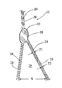
treated or modified composite membrane 12 (Fig. 3), made according to the
present
CA 02498786 2005-03-10
WO 2004/026575
PCT/US2003/021956
invention, may be used in garments or apparel. The composite membrane 12 is
wind
resistant, waterproof, moisture vapor transmissive and air permeable. The
composite
membrane 12 has oleophobicity as the property modified by the treatment method
to offer
protection from contaminating agents, such as oil-containing body fluids in
the form of
5 perspiration.
"Moisture vapor transmissive" is used to describe the passage of water vapor
through a structure, such as the composite membrane 12. The term "waterproof'
is used to
describe that the composite membrane 12 does not "wet" or "wet out" by a
challenge liquid,
such as water, and prevents the penetration of a challenge liquid through the
membrane. The
term "wind resistant" is used to describe the ability of the composite
membrane 12 to prevent
air penetration above more than about three (3) cubic feet per minute (CFM)
per square foot
at a differential pressure drop 0.5 inches of water but has some air
permeability to provide
enhanced comfort to someone wearing the laminated fabric. "Air permeable" is
used to
describe the ability of the composite membrane 12 to permit a relatively small
amount, for
example less than about three (3) CFM per square foot, of air to pass through
it. The term
"oleophobic" is used to describe a material that is resistant to contamination
from absorbing
oils, greases, soap, detergent or body fluids, such as perspiration.
The composite membrane 12 made according to the present invention includes
an untreated or unmodified membrane 16. The untreated or unmodified membrane
16 is
porous, and preferably microporous, with a three-dimensional matrix or lattice
type structure
of numerous nodes 22 interconnected by numerous fibrils 24. The material that
the
membrane 16 is made from may be any suitable material but is preferably made
of expanded
polytetrafluoroethylene (ePTFE) that has preferably been at least partially
sintered.
Generally, the size of a fibril 24 that has been at least partially sintered
is in the range of
about 0.05 micron to about 0.5 micron in diameter taken in a direction normal
to the
longitudinal extent of the fibril.
Surfaces of the nodes 22 and fibrils 24 define numerous interconnecting pores
26 that extend completely through the membrane 16 between opposite major side
surfaces of
the membrane in a tortuous path. Preferably, the average size S of the pores
26 in the
unmodified membrane 16 is sufficient to be deemed microporous, but any pore
size may be
used in the present invention. A suitable average size S for the pores 26 in
the unmodified
membrane 16 may be in the range of 0.01 to 10 microns, and preferably in the
range of 0.1 to
5.0 microns. It is known that a porous ePTFE membrane, while having excellent
CA 02498786 2005-03-10
WO 2004/026575
PCT/US2003/021956
6
hydrophobic properties, is oleophilic. That is, the material making up the
unmodified
membrane 16 is susceptible to contamination by absorbing oil. Once this occurs
the
contaminated regions of the unmodified membrane 16 are considered as "fouled"
because the
pores 26 can be easily wet by a challenge liquid, such as water, and the
membrane is no
longer considered waterproof.
Liquid penetration resistance of the fouled unmodified membrane 16 may be
lost if a challenge fluid or liquid can "wet" the membrane. The unmodified
membrane 16 is
nolinally hydrophobic but loses its liquid penetration resistance when the
challenge liquid
initially contacts and wets a major side of the membrane and subsequently
contacts and wets
the surfaces defining the pores 26 in the membrane. Progressive wetting of the
surfaces
defining the interconnecting pores 26 occurs until the opposite major side of
the porous
membrane 16 is reached by the wetting or challenge liquid. If the challenge
liquid cannot
wet the porous membrane 16, liquid penetration resistance is retained.
The membrane 16 is preferably made by extruding a mixture of
polytetrafluoroethylene (PTFE) fine powder particles (available from DuPont
under the name
TEFLON fine powder resin) and lubricant. The extrudate is then calendared.
The
calendared extrudate is then "expanded" or stretched in at least one and
preferably two
directions to form the fibrils 24 connecting the nodes 22 in a three-
dimensional matrix or
lattice type of structure. "Expanded" is intended to mean sufficiently
stretched beyond the
elastic limit of the material to introduce permanent set or elongation to the
fibrils 24. The
membrane 16 is preferably then heated or "sintered" to reduce and minimize
residual stress in
the membrane material. However, the membrane 16 may be unsintered or partially
sintered
as is appropriate for the contemplated use of the membrane.
Other materials and methods can be used to form a suitable membrane 16 that
has an open pore structure. For example, other suitable materials that may be
used to form a
porous membrane include polyolefin, polyamide, polyester, polysulfone,
polyether, acrylic
and methacrylic polymers, polystyrene, polyurethane, polypropylene,
polyethylene, cellulosic
polymer and combinations thereof. Other suitable methods of making a porous
membrane
include foaming, skiving or casting any of the suitable materials.
= 30 The ePTFE membrane 16 contains many small interconnected
capillary-like
pores 26 (Fig. 3) that fluidly communicate with environments adjacent to the
opposite major
sides of the membrane. Therefore, the propensity of the ePTFE material of the
membrane 16
to adsorb a challenge liquid, as well as whether or not a challenge liquid
would be adsorbed
CA 02498786 2011-03-31
161602A
into the pores 26, is a function of the surface energy of the challenged
material, the surface
tension of the liquid, the relative contact angle between the liquid and
challenged material
and the size or effective flow area of the capillary-like pores.
One way to prevent entry of the challenge liquid into the pores 26 is to make
the
pores extremely small. However, this may be undesirable or impractical.
Another way to
prevent or minimize the loss of resistance to liquid penetration of an ePTFE
membrane is to
have the surface energy of surfaces of the membrane be lower than the surface
tension of the
challenge liquid and the relative contact angle more than 90 . Surface energy
and surface
tension values are typically given in units of dynes/cm. Examples of surface
energies,
relative surface tensions and some measured relative contact angles are listed
in the table
below:
Material Surface Energy Surface Tension Contact Angle
PTFE 18-19 dynes/cm
deionized water 72 dynes/cm 1100 - 112
with tap water varies 114 - 118
SOUrCe
blood 60 dynes/cm 88
perspiration 42 dynes/cm
laundry detergent mix 30.9 dynes/cm 112
MIBK 23.6 dynes/cm 42
acetone 23.5 dynes/cm 37
100% IPA 20.9 dynes/cm 62
hexane 17.9 dynes/cm 52
DEFT 14.8 dynes/cm
liquid CO2 (20 C, 58 bar) 1.5 dynes/cm
supercritical CO2 0.0 dynes/cm
In the course of experimentation it was found that a porous membrane 16
could be coated or treated with a modifier, such as a fluorinated polymer
material in such a
way that enhanced oleophobic property results without compromising the air
permeability of
the membrane. The composite membrane 12 includes a treatment or coating 28
(Fig. 4) on
surfaces of the membrane 16. Most significantly the coating 28 adheres and
conforms to the
surfaces of the nodes 22 and fibrils 24 that define the pores 26 in the
membrane 16. The
coating 28, thus, improves or modifies the oleophobicity of the material of
the membrane 16
to resist contamination from absorbing of contaminating materials such as
oils, body oils in
perspiration, fatty substances, soap, detergent-like surfactants and other
contaminating
7
CA 02498786 2012-04-30
161602 .
8
agents. The composite membrane 12 embodying the present invention remains
durably
liquid penetration resistant when subjected to rubbing, touching, folding,
flexing,
abrasive contact or laundering.
The coating 28 adds a relatively low surface energy layer to an ePTFE
membrane so a relative contact angle of most challenge liquids, oils and
contaminating
agents is greater than 90 so they cannot foul the composite membrane 12.
There are
several such oleophobic polymeric coatings that appear to be suitable. One
example of
a suitable oleophobic coating is a fluorinated urethane polymer and is
marketed as
NRD-342 by DuPont. Most known treatment materials are polymer resins made by
emulsion polymerization and are sold as aqueous dispersions. These polymers
are
typically used to treat fabrics as a treatment for carpets or as a dirt and
stain resistance
treatment. These treatments are typically used on fabric yarns, threads,
filaments and
fibers that are significantly larger in size than the nodes 22 and fibrils 24
of the
membrane 16. These yarns, threads, filaments and fibers are generally made
from
material with a relatively high surface energy that allow aqueous dispersions
to wet and
ultimately treat the entire yarn, thread, filament or fiber. These yarns,
threads,
filaments and fibers also define significantly larger voids even in a tightly
knit or
woven fabric than the pores 26 in the membrane 16 so there is generally no
problem
with coating all surfaces with the particle solids suspended in the water
based
dispersion treatment material.
The preferred aqueous dispersion of treatment material contains relatively
low molecular weight fluorinated urethane polymer particles or "solids". The
dispersion
also includes water and surfactant, such as sodium dodecyl benzene sulfonate
to
suspend the particles in the water and minimize the chance of the solids to
form
agglomerates. The polymer particles are preferably separated from the water
and the
surfactant prior to use according to the present invention. There could be
solvents, co-
solvents or other surfactants in the dispersion without detracting from the
scope of the
present invention. Other suitable treatment materials that include fluorinated
urethane
polymer particles are DuPont's Zony10 C700 or TLF-9526. Another suitable
treatment
material is the Zonyl family of fluorinated acrylic polymers (made by DuPont
and
available from CIBA Specialty Chemicals), such as Zony10 7040. These chemicals
are
also examples of stain resistant treatments typically used for carpets,
textiles, fibers and
fabrics but not microporous membranes.
CA 02498786 2005-03-10
WO 2004/026575
PCT/US2003/021956
9
Substantially improved oleophobic properties of the microporous membrane
16 are realized if the surfaces defining the pores 26 in the membrane and the
major side
surfaces of the membrane are treated or coated with any of the fluorinated
polymers
described above, and especially with the preferred oleophobic fluorinated
urethane polymer
treatment material. The limiting factor previously has been the lack of an
effective way to
introduce the polymer into the pores 26 of the membrane 16 to evenly coat the
surfaces of the
nodes 22 and fibrils 24 that define the pores. The present invention provides
a way to
introduce the polymer into even the smallest pores 26 of the membrane 16 to
apply a
relatively thin and even coating 28 to the surfaces of the nodes 22 and
fibrils 24 that define
the pores without having much of an impact on the size of the pores.
Furthermore, the
present invention provides a way to apply a coating 28 that may modify
properties other than
oleophobicity of the membrane 16, such as hydrophilicity, electrical
conductivity, optical
reflectivity, ion conductivity and color depending on the treatment material
that is used.
It has been found that a fluid under supercritical conditions can dissolve the
preferred fluorinated urethane polymer particles. The solubility of the
preferred treatment
material in supercritical carbon dioxide is illustrated in Fig. 6 at various
concentrations. The
resulting solution is capable of wetting the membrane 16 and entering pores 26
in the
microporous membrane 16 with the dissolved fluorinated urethane polymer. The
solution
with dissolved fluorinated urethane polymer has a surface tension, viscosity
and relative
contact angle that permit the dissolved treatment material to be easily
carried into the smallest
pores 26 of the membrane 16 with the solvent.
The solvent is preferably carbon dioxide in a supercritical phase as
illustrated
in Fig. 5. The surface tension of the supercritical carbon dioxide (SCCO2)
solution is less
than 5.0 dynes/cm, preferably less than 1 dyne/cm and most preferably less
than 0.1 dyne/cm
so it can enter very small areas of the article to be treated. Supercritical
carbon dioxide also
has a viscosity of less than about 0.1 centipoise. The viscosity and surface
tension of the
solution are extremely low so very little resistance to flow is encountered,
thus, lending itself
to the possibility of entering even the smallest pores or areas, such as
between portions of the
PTFE molecules of the membrane 16. Thus, it is possible according to the
present invention
to enter and coat porous membrane material with a relatively small pore size
that has been
heretofore impossible.
Particularly attractive properties are provided by SCCO2 in that it behaves
like
a gas and a liquid at the same time. "When it behaves like a liquid, it can
dissolve material
CA 02498786 2005-03-10
WO 2004/026575
PCT/US2003/021956
and act as a solvent as described above. The density of SCCO2 is about 0.9
grams/cc so it
functions like a solvent. The carbon dioxide is not harmful to the environment
since it is
preferably obtained from sources that create it as a by-product and can be
repeatedly
recovered and re-used. When SCCO2 behaves like a gas it has very low viscosity
and surface
5 tension, so it can enter very small spaces, such as a relatively small
pore in an ePTFE
membrane 16 or spaces or voids in a PTFE node 22, fibril 24 or molecule
forming the
membrane.
The preferred oleophobic fluorinated urethane polymer particles are deposited
onto the surfaces of the nodes 22 and fibrils 24 which define the pores 26 of
microporous
10 membrane 16 to form the coating 28 to reduce the surface energy of the
composite membrane
12. The fluorinated urethane polymer coating 28 of the composite membrane 12
also serves
to increase the contact angle for a challenge liquid relative to the composite
membrane.
Thus, relatively few challenge liquids are capable of wetting the composite
membrane 12 and
enter the pores 26.
The coating 28 of the present invention is disposed on and around surfaces of
the nodes 22 and fibrils 24 that define the interconnecting pores 26 extending
through the
membrane 16. A small amount of the treatment material is also absorbed into
the material of
the membrane 16. Once a predetermined proper amount of fluorinated urethane
polymer
particles is deposited on the membrane 16, it was found that the pores 26 in
the composite
membrane 12 were not dramatically reduced in flow area from that of an
uncoated
membrane. This results in a relatively thin and even coating 28 being applied
to the
membrane 16.
After the ePTFE membrane 16 is manufactured, the oleophobic fluorinated
urethane polymer is applied to the membrane in such a manner that it enters
the pores 26
defined by the surfaces of the nodes 22 and fibrils 24. It is not necessary
that the coating 28
completely encapsulate the entire surface of a node 22 or fibril 24 or is
continuous to increase
oleophobicity of the membrane 16, but it is preferred. The relatively thin
coating 28 results
from evenly depositing numerous small fluorinated urethane polymer particles
on as much of
the surface area of the membrane 16 as possible, including surfaces defining
the pores 26.
The size of the precipitated particle is believed to be in the range of about
1.0
nanometer to about 10.0 nanometers in diameter and preferably in the 1.0
nanometer to 5.0
nanometers range. It is believed that the particle size that is precipitated
depends on the rate
of depressurization. Thus, the ratio of the deposited coating 28 thickness T2
to the fibril 22
CA 02498786 2005-03-10
WO 2004/026575
PCT/US2003/021956
11
size Ti is in the range of 0.2% to 20% and for the preferred particle size the
range is 0.2% to
10%. The ratio of the deposited coating thickness T2 to the effective average
size S of the
pores 26 is in the range of 0.2% to 10% and for the preferred particle size
the range is 0.2% to
5%.
The fluorinated urethane polymer particles engage and adhere to surfaces of
the nodes 22 and fibrils 24 that define the pores 26 in the membrane 16 after
the particles
precipitate out of the solvent. The deposited fluorinated urethane polymer
particles may be
heated on the membrane 16 to flow and cover the surfaces of the nodes 22 and
fibrils 24 and
thereby render the composite membrane 12 even more resistant to contamination
from
absorbing oils and contaminating agents. During the application of heat, the
thermal mobility
'of the fluorinated urethane polymer particles orients the ¨CF3 groups
contained in the
polymer on the nodes 22 and fibrils 24. The ¨CF3 groups of the preferred
polymer orient to
extend into the air to better repel challenge liquids. The fluorinated
urethane polymer coating
28, thus, provides a relatively thin and maximized protective coating on the
membrane 16
that does not completely block or "blind" the pores 26 in the composite
membrane 12, as
illustrated in Fig. 7, that could adversely affect moisture vapor transmission
or air
permeability through the composite membrane.
The composite membrane 12 of the present invention has a relatively high
moisture vapor transmission rate (MVTR) and air permeability while its
oleophobic
properties are improved by the coating 28. The composite membrane 12 has an
oil hold out
of at least a number 6 and preferably is a number 8 as detelinined by AATCC
118 testing. In
some cases, the oleophobicity can be further improved by heating the deposited
material that
forms the coating 28. The composite membrane 12 preferably has a moisture
vapor
transmission rate (MVTR) of at least 50,000 g/m2/day and more preferably at
least 70,000
g/m2/day measured by JIS-1099B2 testing. The composite membrane 12 is air
permeable to
a sufficient degree that a user of apparel made from the composite membrane
can be
relatively comfortable in most conditions and even during periods of extreme
physical
activity. The composite membrane 12 preferably has an air-permeability of at
least 0.20
CFM per square foot of membrane and more preferably at least 0.30 CFM per
square foot of
membrane measured by ASTM D737 testing.
The composite membrane 12 has at least a portion of the fluorinated urethane
polymer treahnent material forming the coating 28 absorbed into the material
of the
membrane 16. That is, portions such as molecules of the fluorinated urethane
polymer
CA 02498786 2005-03-10
WO 2004/026575
PCT/US2003/021956
12
treatment material enter small regions in the PTFE material of the membrane
16. The
portions of the treatment material are engaged by at least two amorphous
portions of the
membrane 16 to mechanically capture and at least partially encapsulate some of
the material
of the coating. Thus, the treatment material of the coating 28 is more
difficult to wash out or
be removed by abrasion or flexing of the composite membrane 12. If some of the
coating 28
is washed away or removed by damage or attrition, the coating is repaired by
absorbed
treatment material exuding from the PTFE.
The treatment material of the coating 28 is absorbed by spaced apart
amorphous portions of PTFE of molecule when the PTFE membrane material swells
as it is
exposed to supercritical carbon dioxide. The PTFE material may swell up to
about 30
percent of its initial size when exposed to supercritical carbon dioxide. The
low viscosity and
low surface tension solution carries the treatment material polymer into
extremely small
voids within of the PTFE material. When the carbon dioxide transitions to a
condition
outside its supercritical phase, the PTFE material is no longer swelled. Any
portions or
molecules of the fluorinated urethane polymer surrounded by the swelled
portions of the
PTFE can be mechanically engaged or trapped by the now unswelled PTFE material
of the
membrane 16. At least a portion of the absorbed fluorinated urethane polymer
can exude
from the membrane. This exuding process is a self-healing mechanism that
maintains the
oleophobic properties of the composite membrane 12 for a relatively long
period of time by
replacing missing or damaged portions of the coating 28. Exuding of the
captured portions of
the coating 28 inherently occurs over time but is accelerated when the
composite membrane
12 is exposed to heat or ultraviolet light, such as sunlight. Heat and
sunlight provide energy
to vibrate the PTFE material. The vibration allows the absorbed material to
overcome the
attractive force holding it in the PTFE material and move or exude from its
original location
inside the PTFE material to the outer surface.
The solution or even supercritical carbon dioxide on its own can also be used
to break the crystalline bonds between portions of the PTFE molecule of the
membrane 16.
Thus, sintering can be performed without heat. This is accomplished by
adjacent crystalline
portions of the PTFE material being forced apart due to swelling when exposed
to
supercritical carbon dioxide. The distance separating these swelled adjacent
portions of the
PTFE molecule exceeds the distance required by Van der Waals forces to
maintain molecular
crystallinity. Thus, this separation becomes permanent and a more amorphous
ePTFE
membrane results.
CA 02498786 2005-03-10
WO 2004/026575
PCT/US2003/021956
13
System Equipment
Equipment 60 for use in the method of treating the membrane 16 according to
the present invention is schematically illustrated in Fig. 1. Lab scale
equipment, based on the
equipment 60, was used in most of the examples described below. The equipment
60
includes a treatment vessel 62 for treating the membrane 16. The treatment
vessel 62 is
preferably in the form of an autoclave capable of withstanding pressure up to
10,000 psi
(about 690 bar) and elevated temperature in the range of 100 C to 300 C (212 F
to 572 F).
The treatment vessel 62 is sized appropriately to treat the desired width and
length of
membrane 16. The treatment vessel 62 is fluidly connected to a supply and
circulation pump
64 by line 66. The treatment vessel 62 has an external heater 68 to maintain
the walls of the
treatment vessel at a predetelinined temperature. The treatment vessel 62 is
located in a fluid
circulation loop connected by line 82 to a temperature control device 84,
optional static mixer
86 and treatment introduction vessel 88. The treatment introduction vessel 88
is connected to
pump 64 through line 102 and valve 104. Valve 104 and valve 106 allow flow
through line
108 to bypass the treatment introduction vessel 88. The temperature control
device 84 may
provide cooling or heating to the line 82 and the fluid contained in the line.
Any or all of the
lines and vessels may be heated or cooled to compensate for cooling when the
CO2 expands
or heating when the CO2 is compressed.
Pump 64 is also connected to a solvent storage container 122 through line 124
and valve 126. The storage container 122 houses liquid solvent under pressure
and is
maintained at a temperature to assure delivery of solvent in a liquid phase to
pump 64. The
treatment vessel 62 is also connected to separation and recovery station 142
through line 144
and valve 146. The separation and recovery station 142 is vented to atmosphere
or may be
optionally connected to the storage container 122 for reusing recovered CO2.
The untreated membrane 16 is rolled onto a core 180, as illustrated in Fig. 2,
and the ends of the roll secured with securement mechanisms 64 such as clamps
to hold the
membrane on the core and prevent fluid flow axially out the ends of the roll.
The securement
mechanisms 64 are preferably radially and circumferentially contractible. The
securement
mechanisms 64 are sufficiently tightened so no fluid flows in a direction
axially out the ends
of the roll of membrane 16 between radially adjacent wraps but radially
through the pores 62
in every wrap of the roll of membrane as indicated by arrows F. The core 180
is made from
any suitable material, such as perforated stainless steel and includes a
multiplicity of
openings 204 extending radially through the core. The core 180 and membrane 16
are
CA 02498786 2005-03-10
WO 2004/026575
PCT/US2003/021956
14
supported in the treatment vessel 62 so the membrane 16 does not contact the
interior of the
treatment vessel 62 and fluid flow can occur around the entire roll of
membrane.
While any suitable connection, support and cap structure may be used, the
core 180 is sealed at one axial end to a core cap 182a that is welded to the
core. The core cap
182a is attached to a removably securable end cap 184 of the treatment vessel
62 by a
threaded connection 182b. The core 180 is shown extending horizontally. It
will be apparent
that the core 180 and treatment vessel 62 could be oriented in a vertical
direction or any other
orientation. The interior of the core cap 182a, threaded connection 182b and
core 180 are in
fluid communication with line 82 through a port in the end cap 184.
The other axial end of the core 180 has a second removably securable core cap
202 that prevents fluid flow out that end of the core. The numerous openings
204 in the core
180 direct fluid to flow radially from the inside the core, through the pores
26 in all the layers
in the roll of membrane 16 and into a space 206 (Fig. 1) between the exterior
of the roll of
membrane and the interior wall 208 of the treatment vessel 62 as indicated by
arrows F
(Fig.2). In operation, a pressure differential of about 30 psi was observed
between the inside
of the core 180 and the outside of the roll of membrane 16. It will be
apparent that the
pressure differential may vary and is a function of fluid flow velocity, roll
size, pore size and
pore density. Fluid flows from the space 206 (Fig. 1) in the treatment vessel
62 through an
opening in a second removably securable end cap 212 of the treatment vessel 62
through a
port and to line 66.
Process
The treatment material may require separation of the polymer particle solids
from the dispersion that it is available in. Particle solids of the preferred
fluorinated urethane
polymer treatment material are placed in the treatment introduction vessel 88.
The amount of
treatment material depends on the solution concentration desired in the
system. The core 180
and roll of membrane 16 are placed in the treatment vessel 62 and connected by
the threaded
connection 182b to end cap 184 for fluid flow through the core and roll. End
caps 184 and
212 are secured to seal the treatment vessel 62. The membrane 16 is made from
a material
that does not dissolve in the selected fluid solvent. Vacuum is applied to the
system and
maintained for sufficient time to remove generally undesired substances like
water and air.
Valve 146 is closed and valve 126 is positioned to allow fluid flow to the
system. Liquid solvent, such as the preferred carbon dioxide, flows from the
storage
container 122 into the treatment vessel 62 and the rest of the system at the
storage pressure.
CA 02498786 2005-03-10
WO 2004/026575
PCT/US2003/021956
Valves 104 and 106 are initially positioned to bypass vessel 88 and create a
closed circulation
loop between the treatment vessel 62 and pump 64. Pump 64 is started to fill
all lines 102,
108, 82 and 66, vessel 62 and mixer 86 and increase pressure. Valve 126 is
positioned to
block flow from container 122 and peimit flow between the pump 64 and
treatment vessel 62.
5 Pump 64 raises the pressure 'in the system to a predetermined pressure.
Valves 104 and 106
are positioned to close off bypass line 108. Fluid flows from the pump 64,
through line 102,
treatment introduction vessel 88, static mixer 86, line 82 and to treatment
vessel 62.
System pressure increases to a desired predeteilnined pressure. The
temperature and pressure of the solvent is controlled as detellnined by the
solubility of the
10 treatment material to be in a phase or condition so the treatment
material may dissolve, as
illustrated in Fig. 6, for a desired solute concentration. Pressure and volume
of solvent may
be increased in a known manner by a make-up supply and pump (not shown).
It has been found that particularly suitable treatment materials are NRD-342
and Zony10 C700. The treatment material is exposed to the fluid when the fluid
is in a phase
15 that can solubilize the treatment material. One such fluid solvent is
carbon dioxide in a
supercritical phase (Fig. 5). For example, when supercritical carbon dioxide
(SCCO2) is at
220 bar or higher pressure and a temperature of 35 C, as illustrated in Fig. 6
for the
concentration of up to 4%, the preferred treatment material NRD-342 particles
dissolve in the
solvent. Each concentration line in Fig. 6 represents a "cloud point" where
the solute
visually becomes insoluble and begins to precipitate out of the supercritical
fluid during a
phase monitor study as a function of pressure. The treatment material solid
particles in the
treatment introduction vessel 88 dissolve in the solvent flowing through it at
supercritical
conditions.
Other treatment materials can be used and have their own solubility
parameters that can be determined in phase monitor studies. It will be
apparent that any
suitable fluid capable of becoming supercritical can be used and the use of a
co-solvent such
as methyl isobutyl ketone (MlBK) may be desired. Flow through the vessel 88
continues
until the desired concentration of the treatment material solute in the
solvent is attained. It
will also be apparent that the treatment material can be in liquid form and
pumped into the
system. It may be desirable to equalize pressure between the interior of the
core 180 and the
exterior 206 of the roll by apparatus not shown until certain system
conditions, such as
concentration, or pressure and/or temperature are reached. This flow path is
maintained until
CA 02498786 2005-03-10
WO 2004/026575
PCT/US2003/021956
16
the desired amount of solids in the treatment introduction vessel 88 is
dissolved to obtain a
desired predetermined concentration of treatment material in the solution.
Once the desired system conditions are reached, the treatment material solute
and solvent in the solution are circulated through the system for an
appropriate predetermined
time. The flow path may be any suitable flow path. By way of example, the
solution is
routed through the pump 64, treatment introduction vessel 88 (or bypassed
through line 108),
static mixer 86, temperature control device 84, line 82, through end cap 184,
into the interior
of the core 180, through the pores 26 in the roll of membrane 16, into the
space 206 in the
treatment vessel 62, through the cap 212, through line 66 and then back to
pump 64. This
assures that every pore 26 in the roll of membrane 16 has been exposed to the
treatment
material. For the NRD-342 and Zonyl C700 treatment materials, a solution
concentration
in the range of 1 weight percent to 5 weight percent in the supercritical
carbon dioxide
solvent was used and found to be suitable.
After the desired concentration of treatment chemical is obtained in the
solution, the solution is circulated in the closed loop system for a
predetermined time to
assure that every pore 26 in every layer of the roll of the membrane 16 has
the treatment
material at the desired concentration of treatment material flowing through
it. The solution of
the treatment material is circulated through the treatment vessel by entering
the cap 184 at a
central location. The end cap 184 has the core 180 attached by connection 182b
(Fig. 2).
The solution of treatment material flows through the core 180, through all the
pores 26 in the
roll of membrane 16 and into the space 206 between the roll of membrane and
the interior
wall 208 of the treatment vessel 62. The solution of the treatment material
then flows though
a port in the end cap 212 and into line 66. When the solution circulates for
sufficient time at
the desired conditions, the pump 64 is stopped. Enough time is allowed to
lapse to assure
that the fluid has stopped moving in the system and particularly in the pores
26 in the
membrane 16 due to its momentum to minimize the chance that treatment material
can be
carried away from the pores with flow.
The pressure and/or temperature of the solution are/is then permitted to
change
to a condition in which the treatment material solute is no longer soluble, as
illustrated in Fig.
6. For example, the pressure is reduced to 150 bar and the temperature is
maintained at 35 C.
The pressure can then be further reduced to atmospheric so the treatment
vessel 62 can be
opened. If the treatment material is soluble in liquid carbon dioxide, the
temperature and
CA 02498786 2005-03-10
WO 2004/026575
PCT/US2003/021956
17
pressure are controlled to keep the carbon dioxide in the gaseous state during
emptying of the
treatment vessel 62.
The treatment material precipitates out of the solution when it first becomes
insoluble. The precipitated treatment material deposits onto the surfaces of
the nodes 22 and
fibrils 24 defining the pores in the porous membrane 16 to form the coating 28
(Figs. 3 and
4). The coating 28 of treatment material is extremely thin and evenly
distributed on the
surface defining the pores 26 of the membrane 16. The deposited treatment
material coating
28 does not block the pores 26 of the membrane 16 so air permeability of the
membrane is
not adversely affected. The particle size of the deposited treatment material
is about 1-5
nanometers. The size of the particle precipitated can be increased by
depressurizing slower.
The deposited treatment material covers all or at least substantially all of
the surface area of
the membrane 16.
At least a portion of the fluorinated urethane polymer is absorbed into
amorphous portions of the membrane 16. This occurs because amorphous portions
of the
PTFE membrane material swell as much as 30 percent from their initial
unswelled size.
When the supercritical carbon dioxide solvent changes from its supercritical
phase to
subcritical, the PTFE material returns to its initial size and portions of the
deposited polymer
treatment material are mechanically encapsulated or "captured" by the PTFE
material of the
membrane 16. At least a portion of the absorbed fluorinated urethane polymer
may exude
from the membrane with time and is accelerated by exposure to heat or to
sunlight.
The membrane modifying method may include exposing the ePTFE
membrane to just carbon dioxide (CO2) at supercritical conditions to swell a
portion of the
ePTFE membrane from an initial size to a swelled size. That is, no treatment
material is
used. The crystalline bonds in the swelled portion of the ePTFE membrane are
broken to
render the swelled portion more amorphous. The ePTFE membrane is removed from
exposure of the carbon dioxide (CO2) at supercritical conditions. The portion
of the ePTFE
membrane returns towards the initial size while retaining the amorphous
condition in that
portion of the ePTFE membrane. DSC results confirm that there was an increase
in
amorphous content.
Post-treatment heat
Heat may optionally be applied to the composite membrane 12 with the
precipitated coating 28 applied. Heat may be applied at about 140 C heat for
about thirty
(30) seconds to the composite membrane 12. The applied heat permits the
coating 28, such
CA 02498786 2005-03-10
WO 2004/026575
PCT/US2003/021956
18
as the fluorinated urethane polymer solids precipitated onto the membrane 16,
to further flow
around the surfaces of the nodes 22 and fibrils 24 to become even more
uniformly distributed
and thinner to render the composite membrane 12 oil and contaminating agent
resistant to a
more significant degree than a composite membrane that has not been heated.
The heat that
is applied to the composite membrane 12 accelerates the fluorine portions (not
shown)
orienting to extend in a direction away from the surfaces of the nodes 22 and
fibrils 24 that
are coated.
Example 1
Approximately 60 yards of ePTFE membrane 16 (QM011SP available from
BHA Technologies, Inc. in Kansas City, Missouri) was wound onto a three inch
outside
diameter perforated core 180 in about 200 wraps. The roll of membrane 16 had
an outside
diameter of about 3.95 inches and a distance between the clamps of 22.3
inches. The average
effective pore size of the membrane 16 was about 0.4 micron. 600 ml of TLF-
9526 treatment
material was placed in the treatment introduction vessel 88. A syringe pump
was connected
to the treatment introduction vessel 88 and one of the circulation lines in
the system. The
treatment material was introduced into a system volume of about 13 liters of
supercritical
CO2 flowing at a rate of about 1500 grams/minute at 300 bar and 40 C by the
pump 64. The
treatment material solution was circulated in the system and flowed through
the core 180 and
membrane 16. The treatment material solution was circulated for one hour and
the system
was depressurized slowly. The membrane 12 removed from the treatment vessel 62
and core
180. The treated membrane 12 was tested. The results are reported in the table
below.
oil hold out air permeability MVTR
roll location
side 1 side 2 side 1 side 2 side 1
side 2
end 1 6 6 0.30 0.25 86000 85000
middle 6 6 0.25 0.34 83000 86000
end 2 7 6 0.39 0.32 86000 86000
Example 2
Approximately 70 yards of ePTFE membrane 16 (QM011 available from
BHA Technologies, Inc. in Kansas City, Missouri) was wound onto the perforated
core 180.
CA 02498786 2005-03-10
WO 2004/026575
PCT/US2003/021956
19
The average effective pore size of the membrane 16 was about 0.5 micron. 284
grams of
TLF-9526 solids treatment material was placed in a treatment introduction
vessel 88 with
fits on each end. The treatment material solids were dissolved by about 13
liters of
supercritical CO2 flowing through the vessel 88. The treatment material
solution was
circulated in the system and flowed through the core 180 and membrane 16 in
both directions
for forty-five minutes. The system was then depressurized quickly. The
membrane 12
removed from the treatment vessel 62 and core 180. The treated membrane 12 was
tested.
The results are reported in the table below.
oil hold out air peimeability MVTR
roll location
side 1 side 2 side 1 side 2 side
1 side 2
end 1 8 8 0.39 0.39 81000 69000
middle 7 7 0.38 0.37 79000 66000
end 2 8 8 0.36 0.38 73000 69000
Example 3
Several trials were perfon-ned by exposing the membrane 16 only to CO2 at
supercritical conditions. This was to deteiiiiine the effects of exposure to
SCCO2. One trial
was perfonned by exposing the membrane 16 to SCCO2 at 280 C at 4000 psi for 60
minutes.
The membrane 12 showed only a slight decrease in Joules/gram by DSC analysis.
A control
sample of the membrane had 62.57 J/gram before exposure to SCCO2 and a
membrane
sample after exposure to SCCO2 measured 60.45 Joules/gram. Another trial was
conducted
by exposing a membrane 16 to SCCO2 at 327 C at 4000 psi for 60 minutes. The
pressure
reduction was done at a rate of 5 psi/minute from 4000 psi to 1000 psi, and
then from a 1000
psi to atmospheric pressure over a 60 minute period. A control sample of this
second
membrane had 47.63 J/gram before exposure to SCCO2 and the second membrane 12
sample
after exposure to SCCO2 measured 27.23 J/gram. Yet another trial was conducted
by
exposing a membrane 16 to SCCO2 at 330 C and 4000 psi for 60 minutes. A
control sample
of this third membrane sample had 57.06 J/gram before exposure to SCCO2 and
the third
membrane 12 sample after exposure to SCCO2 measured 30.86 J/gram.
CA 02498786 2005-03-10
WO 2004/026575
PCT/US2003/021956
Example 4
Approximately 130 yards of ePTFE membrane 16 was wound onto the
perforated core 180. The average effective pore size of the membrane 16 was
about 0.5
micron. 400 grams of TBCU-A solids treatment material was placed in the
treatment
5 introduction vessel 88 with fits on each end. The treatment material was
dissolved by about
13 liters of supercritical CO2 flowing through the treatment introduction
vessel 88. The
treatment material solution was circulated in the system at a rate of about
1600 grams/minute
at 225 bar at an average temperature of 40 C. The treatment material solution
flowed
through the core 180 and membrane 16 from outside the roll and core to inside
the core for
10 thirty minutes and from inside the core to outside the core and roll for
thirty minutes. The
system was then depressurized in a controlled manner to keep the CO2 in a
gaseous state until
pressure reached 800 PSI. Fast depressurization was then permitted. The
membrane 12
removed from the treatment vessel 62 and core 180. The treated membrane 12 was
tested.
The results are reported in the table below.
oil hold out air pettneability MVTR
roll location
side 1 side 2 side 1 side 2 side 1
side 2
end 1 6 6 0.38 0.31 74000 89000
middle 6 6 0.32 0.28 84000 82000
end 2 6 6 0.30 0.24 84000 69000
Example 5
Approximately 130 yards of ePTFE membrane 16 was wound onto the
perforated core 180. The average effective pore size of the membrane 16 was
about 0.5
micron. 488 grams of NRD-342 solids treatment material was placed in the
vessel 88 with
fits on each end. The treatment material was dissolved by about 13 liters of
supercritical
CO2 flowing through the system at a rate of about 1600 grams/minute at 280 bar
and an
average temperature of 37 C. The treatment material solution was circulated in
the system
and flowed through the core 180 and membrane 16 from the inside to the outside
of the roll
of membrane for thirty-four minutes. The system was then depressurized in a
controlled
manner to keep the CO2 in a gaseous state until pressure reached 800 PSI. Fast
depressurization of the treatment vessel was then permitted. The membrane 12
removed
CA 02498786 2005-03-10
WO 2004/026575
21 PCT/US2003/021956
from the treatment vessel 62 and core 180. The treated membrane 12 was tested.
The results
are reported in the table below.
oil hold out air permeability MVTR
roll location
side 1 side 2 side 1 side 2 side
1 side 2
end 1 8 8 0.32 0.31 90000 84000
middle 8 8 0.27 0.28 77000 86000
end 2 8 8 0.24 0.24 79000 72000
Example 6
Vacuum was applied to the system initially. Approximately 130 yards of
ePTFE membrane 16 was wound onto the perforated core 180. The average
effective pore
size of the membrane 16 was about 0.229 micron. 400 grams of NRD-342 solids
treatment
material was placed in the vessel 88 with fits on each end. The treatment
material was
dissolved by about 13 liters of supercritical CO2 flowing through the system
at a rate of about
1600 grams/minute at 280 bar and an average temperature of 36 C. The treatment
material
solution was circulated in the system and flowed through the core 180 and
membrane 16
from the inside to the outside of the roll of membrane for thirty-four
minutes. The system
was then depressurized in a controlled manner to keep the CO2 in a gaseous
state until
pressure reached 800 PSI. Fast depressurization of the treatment vessel 62 was
then
permitted. The membrane 12 removed from the treatment vessel 62 and core 180.
The
treated membrane 12 was tested. The results are reported in the table below.
oil hold out air permeability MVTR
roll location
side 1 side 2 side 1 side 2 side
1 side 2
end 1 8 8 0.23 0.21 76000 67000
middle 8 8 0.22 0.20 62000 49000
end 2 8 8 0.21 0.18 66000 68000
Example 7
To determine if the fluorinated urethane polymer was captured by the ePTFE
membrane by the following procedure. A sample (approximately 5" x 5") of
membrane 12
CA 02498786 2005-03-10
WO 2004/026575
PCT/US2003/021956
22
that initially showed a number 8 oil holdout from Example 5 above was
selected. This
sample was soaked in methyl isobutyl ketone (MIBK) for a few minutes. The
sample was
removed from the MIBK and the surface was wiped with a paper towel. The sample
was
soaked in about fresh MIBK. The sample was removed from the MIBK and the
surface was
wiped with a paper towel. This procedure should ensure that all the
fluorinated urethane
polymer is removed from all the surfaces of the membrane 12. The sample was
air dried
overnight and the oil holdout measured at a number 4 by the AATCC 118 test.
The sample
was then exposed to sunlight for two days and the oil holdout measured at a
number 5. After
heating the sample, the oil holdout remained at a number 5.
Because untreated ePTFE membrane 16 has an oil holdout number of 1, an oil
hold of at least a number 2 suggests that the fluorinated urethane polymer was
mechanically
captured by the ePTFE membrane during the treatment process of the present
invention. The
increase in oil holdout after exposure to sunlight suggests that the
fluorinated urethane
polymer does exude.
Example 8
A wash durability test was conducted to further determine if the fluorinated
urethane polymer was captured by the ePTFE membrane 12. A sample of membrane
12 that
initially showed a number 8 oil holdout from Example 5 above was selected. The
sample
was sewn into a protective shell. Wash water temperature was 80 F without
soap. The
samples were dried at 150 F before each oil holdout test. The results of the
test are shown
below and suggest that the fluorinated urethane polymer is durable on the
membrane 12.
Wash hours Oil holdout
0 8
15 8
8
8
50 8
Example 9
Approximately 249 yards of ePTFE membrane 16 was wound onto the
25 perforated core 180. The average effective pore size of the membrane 16
was about 0.5
micron. The roll of membrane 16 had an outside diameter of about 6.4 inches
and a distance
between the clamps of about 65 inches. 4005 grams of NRD-342 dried solids
treatment
material was placed in the treatment introduction vessel 88 between flits. The
treatment
CA 02498786 2012-04-30
161602
23
material was dissolved by about 105,000 grams of supercritical CO2 flowing
through the
treatment introduction vessel 88. The treatment material solution was
circulated in a
relatively larger scale system than previous treatment examples at a rate of
about 2700
grams/minute at 260 bar at an average temperature of 32 C. The treatment
material
solution flowed through the core 180 and membrane 16 from inside the core to
outside the
core and roll for ninety minutes. The system was then depressurized in a
controlled
manner to keep the CO2 in a gaseous state. The membrane 12 removed from the
treatment vessel 62 and core 180. The treated membrane 12 was tested. The
results are
reported in the table below.
oil hold out air permeability MVTR
roll location
side 1 side 2 side 1 side 2 side 1 side 2
end 1 8 8 0.35 0.35 85000 89000
middle 8 8 0.35 0.38 89000 88000
end2 8 8 0.32 0.28 92000 73000
While there have been described herein what are considered to be preferred and
exemplary embodiments of the present invention, other modifications of these
embodiments falling within the invention described herein shall be apparent to
those
skilled in the art.