Note : Les descriptions sont présentées dans la langue officielle dans laquelle elles ont été soumises.
CA 02499363 2005-03-17
WO 2004/027168 PCT/US2003/029011
OVERFLOW AND DRAIN CONTROL FOR A BATHTUB
Cross Reference To Related Applications
[0001] Not applicable.
Statement Of Federally Sponsored Research Or Development
[0002] Not applicable.
Background Of The Invention
[0003] The present invention relates to a combined
overflow and drain control for a bathing tub. The
control is positionable in an overflow well surrounding
the tub along a bottom surface of the well.
[0004] In many bathtubs an overflow opening is located
through an upper portion of a vertical wall of the tub.
The opening permits water to flow out to a sewer should
the normal drain at the bottom of the tub be closed off
or become clogged while water continues to flow into the
tub in an unabated manner.
[0005] It is conventional to provide a decorative. hood
over such overflow openings to conceal them from view,
while leaving a hole or gap to allow water to
nevertheless reach the overflow opening. It is also
known for a drain control knob or lever to be movably
mounted relative to such hoods to link up to drain
control devices by extending through the overflow
opening. Further linkages connect such knobs or levers
to drain valves at the bottom of the tubs. Thus, such
assemblies provide overflow protection and also provide a
means of controlling the tub drainage.
[0006] A variety of such assemblies exist. These
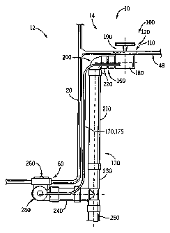
range from assemblies which use electricity to control
the valves (e.g.~U.S. patent 4,945,579 - see also U.S.
patent 5,363,519), to assemblies relying on rigid rods
and levers (e. g. U.S. patent 4,796,310), to assemblies
that rely on sheathed cables (see e.g. U.S. patents
4,594,738 and 5,305,478).
CA 02499363 2005-03-17
WO 2004/027168 PCT/US2003/029011
[0007] In~addition to conventional bathtubs that have
a main basin with a top rim, in recent years there have
.been efforts to provide a more varied set of bathing
.experiences. For example, in U.S. patent 6,360,380 there
was disclosed a deep basin o.f water that allowed an adult
bather's entire torso and legs to be submerged
underwater. Because this device needed to have such a
high level of water the conventional overflow along the
side of the tub was not used.
[0008] Rather, the basin was filled to the absolute
top of it, and the tub was designed so that as.a bather
entered the excess water would spill into an overflow
channel or well surrounding the tub. The overflow and
drain control were placed along a side wall of the well.
[0009] , However, this system was designed to
recirculate water from the well to the main tub. Thus,
an additional outlet was provided on the floor of the
well (much as if it were a bathtub by itself).
[0010] While this system provided desirable additional
bathing experiences, as an alternative it was desired to
provide a somewhat similar basin with a surrounding spill
well, but which did not provide for recirculation of~
spilled over water back to the main tub basin. The
spilled over water would instead be simply drained to the
sewer. Use of an overflow and drain control along the
side wall of such a well could leave a stagnant standing
pool of water in the well once water had reached the
well, at least up to the level of the overflow hole.
[0011] Complicating the design of a drain control for
such a tub is the fact that it is desirable to generally
hide the drain control and overflow feature from view.
Thus it is not desirable to mount the drain control along
the top of the basin rim. Compare the placement of the
control in U.S..patent 3,314,082.
2
CA 02499363 2005-03-17
WO 2004/027168 PCT/US2003/029011
[0012] Therefore, a need still existed for improved
overflow and drain control structures for such tubs.
-Summary Of The Invention
[0013] In one aspect the present invention provides an
overflow and drain control assembly suitable for use. with
a bathing'basin having a drain outlet and an overflow
trough around the basin. The assembly has a drain
channel with an essentially horizontal leg, ~an opening in
an upper wall of the essentially horizontal leg, and a
downwardly extending leg linked to the essentially
horizontal leg.
[0014] There is also a drainpipe suitable for
connection to the drain outlet of the basin and suitable
to communicate with a disposal system. Also provided is
a drain control assembly positioned at least partially in
the drain channel to extend through the opening in the
upper wall of the essentially horizontal leg, and also
which extends outward from the drain channel.
[0015] A drain valve is mounted to the drainpipe.
There is also a means for linking the drain control
assembly to the drain valve such that movement of the
drain control assembly causes movement of the drain
valve.
[0016] In preferred forms the drain control assembly
has a knob that is supported by a shaft, and the shaft in
turn links to a conversion device for converting
rotational motion of the knob into linear motion. An
axis of rotation of the knob can be essentially vertical,
and the means for linking can be a cable that moves in a
sheath. If desired, the drain path can include an elbow
portion linking the essentially horizontal leg to the
downwardly extending leg.
[0017] In another aspect the invention provides a
bathing tub. The tub can be a simple soaking tub, or can
be provided with agitation systems such as hydrotherapy
3
CA 02499363 2005-03-17
WO 2004/027168 PCT/US2003/029011
jets (e. g. spas or whirlpool tubs). In any event, there
is a main basin including a basin floor having a drain
opening in a bottom wall, and an overflow trough coupled
to the main basin and essentially surrounding an upper
portion of the basin, the trough having a bottom wall .
with an overflow opening there through.
[0018] The above assembly is then used with such tub
structures. Because of the location of the assembly at'
the bottom wall of the trough, essentially all water that
enters the overflow trough immediately drains from the
overflow trough. Additionally, the device is
substantially hidden from view (as being at the bottom of
the narrow well). Further, the bent nature of the drain
channel facilitates a compact assembly and minimizes
leakage potential.
[0019] These and other advantages of the invention
will be apparent from the detailed description and
drawings which follow.
Brief Description Of The Drawings
[0020] FIG. Z is an upper, right, frontal perspective
view of a bathtub in which an overflow and drain control
device of the present invention could be applied;
[0021] FIG. 2 is a highly enlarged partial cross-
sectional view taken along line 2-2 of FIG. 1;
[0022] FIG. 3 is a vertical cross-sectional view of a
portion of FIG. 2; and
[0023] FIG. 4 is a partial cross-sectional view taken
along line 4-4 of FIG. 3.
Detailed Description Of The Preferred Embodiments
[0024] Referring first to FIG. 1, a bathtub 10
includes a generally rectangular basin 12 surrounded
about its perimeter at its upper end by an overflow
trough 14 for receiving water flowing over the basin 12.
In this embodiment the bathtub 10 is positioned within a
skirted mounting island (shown in dotted lines). The
4
CA 02499363 2005-03-17
WO 2004/027168 PCT/US2003/029011
usual faucet (not shown) is positioned such that when the
tub is initially being filled the water will drop into
the basin.
[0025] ~ The basin 12 and overflow trough 14 can each be
molded separately from a suitable material (such as
fiberglass with a gel-coating applied to the top
surfaces) to provide a smooth, high gloss finish on the
inside of the basin 12 and overflow trough 14. The basin
12 and the overflow trough 14 can be joined together
along the underside of the basin 12 by a high strength
adhesive. Alternatively, the basin 12 and overflow trough
14 can be formed as a single piece.
[0026] The basin 12 has a bottom 16, generally upright
side walls 18 and 19, a foot wall 20 and a backrest 22.
The bottom 16 can have a raised seat 24 which transitions
into the backrest 22 to form a reclined seat. A bather
can be seated with his or her head at a head end 26 and
feet at a foot end 28, or with his or her head at the
foot end 28 which allows for a second seating position at
an increased depth.
[0027] The side walls 18 and 19, foot wall 20 and
backrest 22 extend up from the bottom 16 sufficiently
high so that an average adult bather seated therein can
be submerged up to his or her neck. Thus, the soaker
bathtub 10 is considerably deeper than other types of
bathtubs. Preferably, the basin is 25" deep at the foot
end 28 and 20" deep at the head end 26.
[0028] Of course, these details of the basin are
merely of a preferred embodiment: .Numerous other
configurations for the basin (e. g. oval) are possible,
and there is no criticality to the floor or back rest
areas of the basin.
[0029] The overflow trough 14 encircling the basin 12
forms a generally rectangular well/trough/channel having
a bottom 48 and opposite inner 50 and outer 52 side
CA 02499363 2005-03-17
WO 2004/027168 PCT/US2003/029011
walls. Unlike a conventional bathtub where the water
cannot rise above a point a few inches below the rim
(because of the presence of an overflow opening), the
entire depth of the basin 12 can be filled with water.
[0030] When the water level reaches the rim 32, it
spills into the overflow trough 14. The bottom 48 of the
overflow trough 14 is pitched so that mater therein runs
from the head end 26 to an overflow orifice 110 at the
foot end 28 (see especially FIG. 2). The conventional
whirlpool suction orifices 50 link the tub water to a
heater (not shown), and that water can be pumped by way
of a recirculation pump (not shown) back into the tub
through one or more injection orifices 52.
[0031] Referring again to FIG. 2, at the bottom 16 of
the basin 12 ,is the usual drain orifice 60, which
includes a drain control valve 260 that allows the drain
orifice to be opened and closed to allow water.to drain,
or prevent water from draining, out of the bathtub 10
into a drainpipe 130. The operation of the drain control
valve 260 is controlled by way of a drain control 100.
As best seen from FIGS. 2-4, the drain control 100 has an
upper hood 190 in which extends a control knob 140 which
is mounted along a generally horizontal section of the
drainpipe 130.
[0032] Note that the control 100 i mounted along the
bottom 48 of the overflow trough 14. Consequently, all
water that enters the overflow trough 14 immediately
drains out. of the overflow trough, instead of
accumulating within the overflow trough up to a side wall
overflow. Additionally, the drain control 100 is still
largely hidden from view, and consequently does not
negatively impact the overall aesthetic~appearance of the
bathtub. The control knob 140 is positioned over the
overflow orifice x.10 to largely shield the orifice from
view.
6
CA 02499363 2005-03-17
WO 2004/027168 PCT/US2003/029011
[0033] Turning now to the details of the assembly,
there is a knob 140 that is supported by a shaft 150 that
extends substantially vertically into a first portion 160
of the drainpipe 130. The shaft 150 extends downward
into a first conversion device 180 preferably directly
below the horizontal portion of the drainpipe 130. 0-
rings 145 are positioned at one or more points along the
length of the shaft 150~to prevent leakage of water into
the first conversion device 180. The first. conversion
device 180, which can be formed integrally with the
drainpipe 130 or is otherwise supported by the drainpipe,
is a stru~cture~for converting rotational motion of the
knob 140/shaft 150 into linear motion of a cable 170.
The cable 170 can be coaxially embedded within a sheath
175 made from rubber, plastic, etc.
[0034] As shown particularly in FIG. 4, in one
embodiment, the first conversion device 180.includes an .
arm 155 that is attached to the bottom of the shaft 150,
where a far end 165 of the arm is attached to the cable
170 by way of a piri 185. Consequently, as the shaft 150
is rotated, the cable 170 is moved relative to the sheath
175. This embodiment of the first conversion device 180
can be compared with the conversion device shown in FIG.
3 of U.S. patent 4,594,738.
[0035] Also as shown in FIGS. 2 and 3, the overflow
opening 110 extends coaxially around the shaft 150.
Flange 190 has a downwardly-directed inner surface 195
(which~in alternate embodiments can be convex). Water
drains from the overflow trough 14, through the overflow
opening 110 down along the inner surface 195 and into the
drainpipe 130 which ultimately connects to a sewer.
[0036] The first portion 1-60 of the drainpipe 130
extends in a generally horizontal direction until it
reaches an elbow 200. From the elbow 200 a second
portion 210 of the drainpipe 130 extends in a generally
7
CA 02499363 2005-03-17
WO 2004/027168 PCT/US2003/029011
vertical direction. Conversion device 180 therefore has
a position_for location that is adjacent the tub, yet in
proper alignment relative to the shaft 150 and knob 140.
The elbow 200 can be connected to the first and second
portions 160,210 by way of standard threaded coupling
portions 220.
[0037] Second portion 210 of the drainpipe 130 in turn
is coupled to portion 230 of the drainpipe 130, which~is
T-shaped. The T-shaped portion 230 is linked in the
usual manner to a vertical pipe 250 extending to the
sewer and a generally horizontal pipe 240. The latter is
coupled to the drain opening 60.
[0038] Zocated within the drain opening 60 is the
drain control valve 260, the positioning of which is
determined by movement of the cable 170 through
facilitation by way of a second conversion device 280.
The latter device converts linear motion of the cable
into vertical linear motion of the drain control valve
260.
[0039] In one embodiment, the second conversion device
280 is similar to the first conversion device 180 in that
the cable 170 is coupled to a first arm that is attached
to a rotatable shaft (not shown). As movement of the
cable and consequently the first arm occurs, the shaft is
rotated, and an additional arm (not shown) attached to
the shaft is thus also rotated. The drain control valve
260, which rests upon the additional arm, moves upward
when so forced by the additional arm, and moves downward
due to gravity when the additional arm is retracted.
This embodiment can be compared with that shown in U.S.
Patent No. 4,594,738. Thus, rotation of the knob 140
along a vertical axis causes corresponding upward or
downward movement of the drain control valve 260.
[0040] Importantly, the design is suitable for use
with tubs having a variety of sloped walls 20 as the
8
CA 02499363 2005-03-17
WO 2004/027168 PCT/US2003/029011
length of the elbow will ensure enough of a gap between
the pipe 210 and the wall 20 to permit sloping of the
wall. 20 such as at a back rest. The design of the drain
control 100 is suitable for implementation at different
locations along the overflow trough 14, alongside
different walls than the foot wall 20.
[0041] A variety of alternate embodiments of the
present invention are possible in addition to those
shown. Most particularly, it is envisioned that another
preferred bathtub will have a generally oval basin
surrounded by a generally oval overflow trough. Also,
while the preferred tubs have no recirculation to the
main basin from the overflow trough, such tubs could be
provided with reci:rculation systems instead of dumping
the overflow water to the sewer.
[0042] Further, while a cable linkage is the most
preferred linkage, it will be appreciated~that other
types of linkages (e. g. mechanical; electrical) are also
possible. Moreover, a rotational knob can be replaced
with other activation mechanisms (e. g. compare U.S.
patent 4,7.96,310 which uses a lever).
[0043] Thus, while the foregoing illustrates and
describes the preferred embodiments of the present
invention, reference should be made to the following
claims, rather than to just the foregoing specification,
as indicating the scope of the invention.
Industrial Applicability
[0044] The invention provides overflow and drain
control assemblies, particularly those useful in
connection with overflow troughs around bathing basins.
9