Sélection de la langue

Search

Sommaire du brevet 2500055 

Énoncé de désistement de responsabilité concernant l'information provenant de tiers

Une partie des informations de ce site Web a été fournie par des sources externes. Le gouvernement du Canada n'assume aucune responsabilité concernant la précision, l'actualité ou la fiabilité des informations fournies par les sources externes. Les utilisateurs qui désirent employer cette information devraient consulter directement la source des informations. Le contenu fourni par les sources externes n'est pas assujetti aux exigences sur les langues officielles, la protection des renseignements personnels et l'accessibilité.

Disponibilité de l'Abrégé et des Revendications

L'apparition de différences dans le texte et l'image des Revendications et de l'Abrégé dépend du moment auquel le document est publié. Les textes des Revendications et de l'Abrégé sont affichés :

  • lorsque la demande peut être examinée par le public;
  • lorsque le brevet est émis (délivrance).
(12) Brevet: (11) CA 2500055
(54) Titre français: ELEMENT DE TRANSITION DE TRAVERSE EXTREME POUR WAGON A MARCHANDISES
(54) Titre anglais: RAILWAY FREIGHT CAR END SILL TRANSITION MEMBER
Statut: Accordé et délivré
Données bibliographiques
(51) Classification internationale des brevets (CIB):
  • B61F 1/08 (2006.01)
(72) Inventeurs :
  • GRAY, JAMES A. (Etats-Unis d'Amérique)
(73) Titulaires :
  • ASF-KEYSTONE, INC.
(71) Demandeurs :
  • ASF-KEYSTONE, INC. (Etats-Unis d'Amérique)
(74) Agent: GOWLING WLG (CANADA) LLP
(74) Co-agent:
(45) Délivré: 2008-07-08
(22) Date de dépôt: 2005-03-09
(41) Mise à la disponibilité du public: 2006-01-12
Requête d'examen: 2005-03-09
Licence disponible: S.O.
Cédé au domaine public: S.O.
(25) Langue des documents déposés: Anglais

Traité de coopération en matière de brevets (PCT): Non

(30) Données de priorité de la demande:
Numéro de la demande Pays / territoire Date
10/888,847 (Etats-Unis d'Amérique) 2004-07-12

Abrégés

Abrégé français

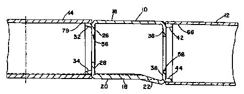
Il s'agit d'un élément de transition pour wagon de marchandises. L'élément de transition permet de relier les différentes sections transversales du châssis à la traverse de traction et au longeron central d'un wagon de marchandises. L'élément de transition est habituellement une structure unitaire en acier moulé, dotée généralement d'une section transversale rectangulaire ou carrée.


Abrégé anglais

A transition member for use in a railway freight car is provided. The transition member provides connection between the dissimilar cross sections of the underbody and draft sill of the railway freight car and the center sill of the railway freight car. The transition member is usually a unitary cast steel structure and is of a generally rectangular or square cross section.

Revendications

Note : Les revendications sont présentées dans la langue officielle dans laquelle elles ont été soumises.


CLAIMS:
1. A transition member for use in a railway freight car, the railway freight
car comprising:
a truck assembly, an underframe assembly and a center sill, the underframe
assembly
includes a draft sill that provides connection between the underframe assembly
and the truck
assembly, an end sill,
wherein the transition member connects between the end sill and the draft
sill,
the transition member comprising a generally rectangular in cross section
elongated
structure, including a top section, bottom section and two spaced wall
sections that extend
between the top section and the bottom section,
wherein the transition member includes a first end and a second end,
the first end is comprised of first edges of the top section, main part of the
bottom section
and two wall sections,
and the second end is comprised of second edges of the top section, tapered
part of the
bottom section and the two wall sections,
wherein the first end is received in an opening in the center sill and the
second end is
received in an opening in the draft sill,
further comprising a second support rib structure extending inwardly from each
of the top
section, bottom section and the two wall sections to form a continuous support
rib at the second
end of the transition member,
wherein the top section, bottom section and two wall sections each include a
tapered
protrusion that extends outwardly beyond the second support rib structure at
the second end of
the transition member.
-7-

2. The transition member of claim 1 wherein the bottom section of the
transition member
has a thickness and the top section of the transition member has a thickness,
and the thickness of
most of the length of the bottom section exceeds the thickness of the top
section.
3. The transition member of claim 1 wherein the bottom section is comprised of
a main part
and a distal part, the main part of the bottom section being generally
parallel with the top section,
and the distal part of the bottom section extending downwardly at an acute
angle from the main
part.
4. The transition member of claim 1 wherein the transition member is a unitary
steel casting
of a generally square shape in cross section.
5. The transition member of claim 1 wherein the bottom section includes two
wing sections,
each wing section extending outwardly beyond the wall section.
6. The transition member of claim 5 wherein each wing section includes a main
section that
extends for a length about equal to the length of the main part of the bottom
section and an
angled section that extends for a length about equal to the length of the
distal part of the bottom
section.
7. The transition member of claim 6 wherein the angled section of each wing
section
extends at an acute angle from the main section of the wing section to the
wall section of the
transition member.
8. The transition member of claim 3 wherein the distal part of the bottom
section is of a
tapering thickness.
9. The transition member of claim 1 wherein the transition member is comprised
of a
unitary cast steel structure.
10. The transition member of claim 1 further comprising a first support rib
structure
extending inwardly from each of the top section, bottom section and two wall
sections to form a
continuous support rib structure at the first end of the transition member.
-8-

11. The transition member of claim 1 wherein the top section and the two wall
sections are
tapered inwardly at the first end.
-9-

Description

Note : Les descriptions sont présentées dans la langue officielle dans laquelle elles ont été soumises.


CA 02500055 2005-03-09
RAILWAY FREIGHT CAR END SILL TRANSITION MEMBER
BACKGROUND OF THE INVENTION
The present invention relates to railway freight car draft sills and center
sills and, more
particularly, to a transition member for use in connecting between the
dissimilar cross sections of
a draft sill and a center sill of a railway freight car.
The prevalent construction of railway freight cars includes the use of two
truck
assemblies at either end of each car body. Each truck assembly is comprised of
two sideti-ames
that are spaced laterally and are parallel with the railway tracks. A bolster
extends laterally
between the two sideframes to form what is commonly referred to as a three
piece railway freight
car truck.
The railway freight car body itself includes a center sill structure which
extends
longitudinally the virtual entire length of the freight car to provide the
main support member for
the railway freight car. Ends of the center sill include draft sills, which
can be fabricated or cast.
Such draft sills include a center plate for connection to a center bowl
structure located on the
truck bolster. Further, an end sill is connected to the railway freight car
body in alignment with
the center sill, but near each end of the railway freight car. The end sill is
designed to receive a
coupler assembly.
It is desirable to provide a connection between the dissimilar cross sections
of a draft sill
and the end sill that is adaptable to the various designs of railway freight
cars.
Accordingly, it is an object of the present invention to provide an improved
transition
member for use in connection between the draft sill and end sill of a railway
freight car.

CA 02500055 2005-03-09
SUMMARY OF THE INVENTION
25 The present invention relates to a railway freight car that includes an
underframe
assembly comprising a draft sill and an end sill. The end sill is associated
and receives the
various components of the coupler assembly. It is desirable to provide a
transition connection
between the draft sill and end sill that accommodates various designs and
structures of the
railway freight car. Accordingly, the present invention in particular relates
to a transition
30 member that connects between the dissimilar cross sections of a draft sill
structure of the railway
freight car and the end sill.
The transition member of the present invention is usually a unitary cast steel
structure
that is generally rectangular in cross section. The transition member can be
of varying lengths,
but the transition member of the present invention is of a length that is
greater than its height or
35 its width. The transition member of the present invention includes
structural features that
provides strength, durability, and adaptability in the railway freight car to
allow connection
between various locations of the draft sill and the end sill.
BRIEF DESCRIPTION OF THE DRAWINGS
Referring now to the drawings,
40 Fig. 1 is a side view, in partial cross section, of a transition member in
accordance with
the present invention connected between a draft sill and an end sill;
Fig. 2 is a side view of the transition member in accordance with the present
invention;
Fig. 3 is a side view, in cross section, of the transition member in
accordance with the
present invention;
45 Fig. 4 is a partial bottom view of the transition member in accordance with
the present
invention;
~2~

CA 02500055 2005-03-09
Fig. 5 is an end view of the second end of the transition member in accordance
with the
present invention;
Fig. 6 is an end view of the first end of the transition member in accordance
with the
50 present invention;
Fig. 7 is a side view, in cross section, of an end sill of a railway freight
car, and
Fig. 8 is a side view, in partial cross section, of a draft sill of a railway
freight car.
DETAILED DESCRIPTION OF THE INVENTION
Referring now to Fig. 1 of the drawings, transition member 10 in accordance
with the
55 present invention is shown generally at 10.. Transition member 10 is seen
to be comprised of a
generally rectangular in cross section, elongated structure. Such transition
member 10 is usually
comprised of an integral cast steel device. Transition member 10 is seen to be
comprised of top
section 16, which is generally of rectangular configuration. Bottom section 18
itself is seen to be
comprised of a main part 20 and a distal part 22 extending downwardly toward
what is deemed
60 the second end of transition member 10. It is seen that the second end of
transition member 10
intersects with end sill 12. Also part of the second end of transition member
10 are second end
top section support rib 36 which is seen to extend downwardly from top section
16, and second
end bottom section support rib 38 which is seen to extend upwardly along the
lateral width of the
end of distal part 22. Also extending outwardly from the intersection of top
section 16 and
65 support rib 36 is a second end tapered projection 42. Tapered projection 42
is seen to be located
downward below top section 16. Similarly, extending outwardly from the
intersection of bottom
section distal part 22 and bottom section support rib 38 is bottom section
second end tapered
protrusion 44. Tapered protrusion 44 is seen to be located upwardly from the
very bottom edge
of distal part 22.
~3~

CA 02500055 2005-03-09
70 At the first end of transition member 10, where connection is made tv draft
sill 14, top
section support rib 26 extends downwardly from tap section 16 and extends
across the width of
transition member 10. Similarly, bottom section support rib 28 extends
upwardly from the
bottom section 18 of transition member 10 and extends across the width of
transition member 10.
Tapered protrusion 32 extends outwardly from support rib 26 and extends across
the width of
75 transition member 10. It is also seen that tapered protrusion 32 extends
from a height below that
of the top of top section 16. Similarly, bottom section tapered protrusion 34
extends outwardly
from bottom section support rib 28, and extends across the width of transition
member 10.
Tapered protrusion 34 is seen to extend outwardly from a height above that of
the bottom of
bottom section 18.
80 Bottom section 18 is seen to be comprised of a generally rectangular main
part 20 of a
thickness greater than that of top section 16. Further, bottom section distal
part 22 is seen to be
again a generally rectangular section but extending downwardly from the level
of bottom section
18 to intersect with bottom section support rib 38. Further, it is seen that
the thickness of distal
part 22 decreases as distal part 22 extends to join bottom section support rib
38.
85 Referring now to Figs. 2-6 of the drawings, detailed views of transition
member 10 are
provided. Transition member 10 is seen to be comprised of top section I6,
bottom section 18,
and wall sections 17 and 19. As described above with reference to Fig. 1,
transition member 10
is seen to be of a generally rectangular or square cross section and of an
elongated nature such
that the length of transition member 10 is seen to exceed both its height and
width.
90 Transition member 10 is seen to comprise bottom section wing section 27
extending
outwardly beyond wall section 17, and bottom section wing section 29 extending
outwardly
beyond wall section 19. Wing section 29 is seen to be comprised of a generally
rectangular main
~4~

CA 02500055 2005-03-09
section 39 that extends longitudinally from the first end of transition member
10 toward the
second end, but wing section 29 is also seen to comprise angled section 41
which is contiguous
95 with main section 39 but extends inwardly at an acute angle from main
section 39 to intersect
vuath the second end of transition member 10. Bottom section wing section 27
also comprises a
similar main section and an angled section.
Transition member first end top section support rib 26 and transition member
first end
bottom section support rib 28 are seen to extend such that a circular opening
is formed therein. It
100 is also seen that top section support rib 26 and bottom section support
rib 28 extend and engage
both of wall section 17 and 19. Circular opening 56 is seen to be formed by
top section support
rib 26 and bottom section support rib 28. Similarly, second end top section
support rib 36
extends laterally to engage both of wall sections 17 and 19, and second end
bottom section
support rib 38 extends similarly to engage both wall sections 17 19. It is
seen that second end
105 top section support rib 36 and second end bottom section support rib 38
combine to form a
generally rectangular opening 58 at the second end of transition member 10.
Referring now to Fig. 7, a side view of end sill is shown generally at 12. End
sill 12 is
seen to be comprised of a top section 64, and a bottom section 62, which are
generally
rectangular in nature yet elongated such that the length of end sill 12 is
much greater than its
110 height or width. Further, end sill 12 is comprised of side walls that join
top wall 64 and bottom
wall 62. An opening 74 is located at the second end of end sill 12 to
accommodate a coupler
yoke and shank. Opening 66 is shown at the first end of end sill 12. It is
shown in Figure 1 that
the second end of transition member 10 is received into the first end 66 of
end sill 12. End sill
12 can be a fabricated structure or it can be a unitary cast structure.

CA 02500055 2005-03-09
115 Referring now to Figure 8, a draft sill is shown generally at 14. Draft
sill 14 is seen to be
comprised of a bottom section 72 and a top section 74, joined by two laterally
spaced walls.
Draft sill 14 is seen to be of a generally rectangular configuration, but of a
length much greater
than its height or width. Bottom section 72 of draft sill 14 is seen to also
comprise a center plate
76, with a centrally located opening 78. Center plate 76 is usually of a
circular configuration, as
120 is opening 78. Such center plate 76 is received in a complementary
circular opening in the top
surface of the railway freight car truck bolster. Draft sill 14 is seen to be
comprised of a first end
79, of a generally rectangular or square configuration. First end 79 of draft
sill 14 is seen to be
fit around first end tapered protrusions 32 and 34. It is usually desired that
such fit is completed
by welding.
125
~6~

Dessin représentatif
Une figure unique qui représente un dessin illustrant l'invention.
États administratifs

2024-08-01 : Dans le cadre de la transition vers les Brevets de nouvelle génération (BNG), la base de données sur les brevets canadiens (BDBC) contient désormais un Historique d'événement plus détaillé, qui reproduit le Journal des événements de notre nouvelle solution interne.

Veuillez noter que les événements débutant par « Inactive : » se réfèrent à des événements qui ne sont plus utilisés dans notre nouvelle solution interne.

Pour une meilleure compréhension de l'état de la demande ou brevet qui figure sur cette page, la rubrique Mise en garde , et les descriptions de Brevet , Historique d'événement , Taxes périodiques et Historique des paiements devraient être consultées.

Historique d'événement

Description Date
Représentant commun nommé 2019-10-30
Requête pour le changement d'adresse ou de mode de correspondance reçue 2018-01-16
Exigences relatives à la nomination d'un agent - jugée conforme 2010-06-23
Exigences relatives à la révocation de la nomination d'un agent - jugée conforme 2010-06-23
Inactive : Lettre officielle 2010-06-22
Demande visant la révocation de la nomination d'un agent 2010-06-10
Demande visant la nomination d'un agent 2010-06-10
Accordé par délivrance 2008-07-08
Inactive : Page couverture publiée 2008-07-07
Inactive : Taxe finale reçue 2008-04-18
Préoctroi 2008-04-18
month 2008-03-11
Un avis d'acceptation est envoyé 2008-03-11
Lettre envoyée 2008-03-11
Inactive : Approuvée aux fins d'acceptation (AFA) 2007-12-20
Modification reçue - modification volontaire 2007-06-27
Inactive : Dem. de l'examinateur par.30(2) Règles 2007-03-15
Demande publiée (accessible au public) 2006-01-12
Inactive : Page couverture publiée 2006-01-11
Inactive : CIB en 1re position 2005-05-17
Inactive : Certificat de dépôt - RE (Anglais) 2005-04-14
Lettre envoyée 2005-04-14
Demande reçue - nationale ordinaire 2005-04-14
Exigences pour une requête d'examen - jugée conforme 2005-03-09
Toutes les exigences pour l'examen - jugée conforme 2005-03-09

Historique d'abandonnement

Il n'y a pas d'historique d'abandonnement

Taxes périodiques

Le dernier paiement a été reçu le 2008-01-21

Avis : Si le paiement en totalité n'a pas été reçu au plus tard à la date indiquée, une taxe supplémentaire peut être imposée, soit une des taxes suivantes :

  • taxe de rétablissement ;
  • taxe pour paiement en souffrance ; ou
  • taxe additionnelle pour le renversement d'une péremption réputée.

Les taxes sur les brevets sont ajustées au 1er janvier de chaque année. Les montants ci-dessus sont les montants actuels s'ils sont reçus au plus tard le 31 décembre de l'année en cours.
Veuillez vous référer à la page web des taxes sur les brevets de l'OPIC pour voir tous les montants actuels des taxes.

Titulaires au dossier

Les titulaires actuels et antérieures au dossier sont affichés en ordre alphabétique.

Titulaires actuels au dossier
ASF-KEYSTONE, INC.
Titulaires antérieures au dossier
JAMES A. GRAY
Les propriétaires antérieurs qui ne figurent pas dans la liste des « Propriétaires au dossier » apparaîtront dans d'autres documents au dossier.
Documents

Pour visionner les fichiers sélectionnés, entrer le code reCAPTCHA :


Pour visualiser une image, cliquer sur un lien dans la colonne description du document (Temporairement non-disponible). Pour télécharger l'image (les images), cliquer l'une ou plusieurs cases à cocher dans la première colonne et ensuite cliquer sur le bouton "Télécharger sélection en format PDF (archive Zip)" ou le bouton "Télécharger sélection (en un fichier PDF fusionné)".

Liste des documents de brevet publiés et non publiés sur la BDBC .

Si vous avez des difficultés à accéder au contenu, veuillez communiquer avec le Centre de services à la clientèle au 1-866-997-1936, ou envoyer un courriel au Centre de service à la clientèle de l'OPIC.


Description du
Document 
Date
(yyyy-mm-dd) 
Nombre de pages   Taille de l'image (Ko) 
Description 2005-03-08 6 240
Abrégé 2005-03-08 1 10
Revendications 2005-03-08 7 205
Dessins 2005-03-08 5 58
Dessin représentatif 2005-12-14 1 8
Page couverture 2005-12-21 1 32
Revendications 2007-06-26 3 82
Page couverture 2008-06-10 1 32
Paiement de taxe périodique 2024-02-19 49 2 016
Accusé de réception de la requête d'examen 2005-04-13 1 176
Courtoisie - Certificat d'enregistrement (document(s) connexe(s)) 2005-04-13 1 104
Certificat de dépôt (anglais) 2005-04-13 1 157
Rappel de taxe de maintien due 2006-11-13 1 112
Avis du commissaire - Demande jugée acceptable 2008-03-10 1 164
Correspondance 2008-04-17 2 48
Correspondance 2010-06-09 8 328
Correspondance 2010-06-21 1 15