Note : Les descriptions sont présentées dans la langue officielle dans laquelle elles ont été soumises.
CA 02500308 2005-03-21
WO 2004/070072 PCT/US2004/001526
HEAT TREATABLE COATED ARTICLE WITH CHROMIUM NITRIDE IR
REFLECTING LAYER AND METHOD OF MAKING SAME
[0001] This invention relates to coated articles that include at least one
chromium
nitride infrared (IR) reflecting layer sandwiched between at least a pair of
dielectric
layers, and/or a method of making the same. Such coated articles rnay be used
in the
context of monolithic windows, insulating Glass (IG) window units, laminated
windows, and/or other suitable applications.
BACKGROUND OF THE INVENTION
[0002] The need for color matchability of coated articles (before heat
treatment
vs. after heat treatment) is known. Glass substrates are often produced in
large
quantities and cut to size in order to fulfill the needs of a particular
situation such as a
new multi-window and door office building, other window needs, etc. It is
often
desirable in such applications that some of the windows andlor doors be heat
txeated
(i.e., tempered, heat strengthened or bent), while others need not be. Office
buildings
often employ IG units and/or laminates for safety andlor thermal control. It
is often
desirable that the units andlor laminates which are heat treated (HT)
substantially mateh
their non-heat treated counterparts (e. g., with regard to color, reflectance,
and/or the
like) for architectural and/or aesthetic purposes.
[0003] U.S. Patent No. ~,376,~.55 discloses a coated article including:
glass/Si;Na/NiCrIAJNiCr/Si;N~.. Unfortunately, the coating system of the '=15~
patent
is not sufficiently color matchable after heat treatment with its non-heat-
treated
counterpart. In other words, the coating system of the '453 patent has a
rather high 0E
value. This means that, unfortunately, two different coated articles with
different
coatings (one to be heat treated, the other not to be) must be made for
customers who
want their heat-treated and non-heat-treated coated articles to approximately
match
CA 02500308 2005-03-21
WO 2004/070072 PCT/US2004/001526
2
colorwise as viewed by the naked eye.
[0004] As with the '455 patent, it has mostly been possible to achieve
matchability only by providing two different layer systems, one of which is
heat treated
(HT) and the other is not. The necessity of developing and using two different
layer
systems to achieve matchability creates additional manufacturing expense and
inventory needs which are undesirable.
[0005] However, commonly owned U.S. Patent No. 5,688,585 discloses a solar
control coated article including glass/Si;N~/NiCr/Si;N~., wherein matchability
is
achieved with a single layer system. As explained at column 9 of the '585
patent, it is a
"requirement" of the '585 invention that the NiCr layer be substantially free
of any
nitride. An object of the '585 patent is to provide a sputter coated layer
system that
after heat treatment is matchable colorwise with its non-heat-treated
counterpart.
However, the '585 patent uses a heat treatment (HT) of only three (3) minutes
(col. 10,
line 55). Longer heat treatments are often desired in order to attain better
tempering or
HT characteristics. Unfortunately, as explained below, it has been found that
with
longer HT times the coatings of the'S85 patent cannot maintain low dE values
and thus
lose color matchability.
[0006] Consider the following layer stack: glass/Si;N~/NiCr/Si;N~, where the
underlayer of Si;N~ is about 50-70 ~ (angstroms) thick, the NiCr layer is
about 325 ~
thick (the NiCr layer is not nitrided as deposited as can be seen in Fig. 15),
and the
overcoat of Si;N~ is about 210-310 ~. thick. It is noted that some amount of
nitriding of
the NiCr may possibly occur during heat treatment. Unfortunately, given the
deposited
NiCr layer, this coated article has a rather high transmissive DE* va'lue of
about 5.9
after a heat treatment (HT) at 625 degrees C for ten ( 10) minutes. This high
transmissive 0E value means that a HT version of the '585 coated article does
not
approximately match colorwise non-heat-treated counterpart versions with
regard to
transmissive color after 10 minutes of HT. Moreover, such stacks have a glass
side
reflective ~E* value of above 5.0 after heat treatment (HT) at 625 degrees C
for ten
minutes. These high glass side reflective DE* values are not desirable, and
they
prevent appearance matchability between HT and non-HT versions of the same
coating.
CA 02500308 2005-03-21
WO 2004/070072 PCT/US2004/001526
3
[0007] Unfortunately, the layer stack of glass/Si;N4/NiCr/ Si;N~., where the
NilCr
ratio is 80/20, while providing efficient solar control and being overall good
coatings, is
also sometimes are lacking in terms of: (a) corrosion resistance to acid
(e.g., HCl boil);
and (b) mechanical performance such as scratch resistance; in addition to the
problems
described above associated with (c) thermal stability upon heat treatment for
tempering,
heat bending, or the like (i.e., ~E* value(s)).
[000] Accordingly, there exists a need in the art for a coated article that
has
improved characteristics with respect to (a), (b) and/or (c) compared to a
conventional
layer stack of glass/Si;N4/NiCr/Si;N4, but which still is capable of
acceptable solar
control (e.g., blocking a reasonable amount of IR and/or UV radiation) and/or
heat
treatment. It is a purpose of this invention to fulfill at least one of the
above-listed
needs, and/or other needs which will become apparent to the skilled artisan
once given
the following disclosure.
SUMMARY OF THE INVENTION
[0009] In certain example embodiments of this invention, a coating or layer
system is provided which includes an infrared (IR) reflecting layer comprising
chromium nitride sandwiched between at least a pair of dielectric layers. In
certain
example embodiments, the coating or layer system has good corrosion resistance
to
acids) such as HCI, good mechanical performance such as scratch resistance,
and/or
good color stability (i.e., a low DE* value(s)) upon heat treatment (HT).
[0010] For example, a coating or layer system including an I]2 reflecting
layer
comprising chromium nitride has been found to have better durability (e.g.,
with respect
to acid exposure) than the aforesaid conventional coating including a NiCr IR
reflecting
layer. Moreover, it has surprisingly been found that the use of chromium
nitride as an
IR reflecting layer enables a solar control coating to have significantly
improved
stability upon HT (e.g., a lower ~E* value with a given HT time) than the
aforesaid
conventional coating where metallic NiCr is used as the IR reflecting layer.
CA 02500308 2005-03-21
WO 2004/070072 PCT/US2004/001526
4
[0011] A coated article according to an example embodiment of this invention
utilizes such a chromium nitride layer sandwiched between a pair of silicon
nitride
dielectric layers.
[0012] Coated articles according to certain embodiments of this invention may
be used as monolithic windows due to their excellent durability
characteristics, which
may or may not be heat treated. Alternatively, coated articles according to
this
invention may also be used in the context of insulating glass (IG) window
units, or in
other suitable application, which may or may not involve heat treatment.
[0013] In certain example embodiments of this invention, heat treated (HT)
coated articles including a chromium nitride IR reflecting layer have a DE*
value (glass
side reflective andlor transmissive) of no greater than 5.0, still more
preferably no
greater than 4.0, more preferably no greater than 3.0, even more preferably no
greater
than 2.5, still even more preferably no Greater than 2.0, and most preferably
no greater
than 1.8. For purposes of example, the heat treatment (HT) may be for at least
about 5
minutes at a temperatures) of at least about 580 degrees C, and may be at a
temperature of at least about 600 decrees C for a period of time of at least 5
minutes
(more preferably at least 7 minutes, and most preferably at least 9 minutes)
in certain
example embodiments.
[0014] In certain example embodiments of this invention, the IR reflecting
layer
which is sandwiched between at least a pair of dielectric layers may comprise,
consist
essentially of, or consist of chromium nitride. In certain example
embodiments, the
chromium nitride IR reflecting layer may be represented by CrXNy, where the
y/x ratio
is from 0.25 to 0.7, even more preferably from 0.3 to 0.6, still more
preferably from
0.45 to 0.55. For purposes of example only, Cr~N translates into a y/x ratio
of 1/? (i.e.,
0.5). It has surprisingly been found that these particular y/x ratio ranges)
for nitrides
of chromium(Cr) are particularly beneficial with respect to thermal, optical
and/or
durability characteristics. For instance, nitriding of Cr in amounts greater
than this
may result in less durability (e.g., mechanical and/or chemical resistance).
[0015] Generally speaking, certain example embodiments of this invention
fulfill
CA 02500308 2005-03-21
WO 2004/070072 PCT/US2004/001526
one or more of the above listed needs by providing a heat treated coated
article
comprising: a layer system supported by a glass substrate, said layer system
comprising a layer comprising chromium nitride located between first and
second
dielectric layers, wherein the second dielectric layer is at least partially
nitrified and
positioned so that the layer comprising chromium nitride is between the second
dielectric layer and the glass substrate; and wherein said coated article has
a ~E* value
(glass side reflective andlor transmissive) no greater than 4.0 after heat
treatment at a
temperatures) of at least about 600 degrees C.
[0016] In certain other example embodiments of this invention, one or more of
the above-listed needs is/are fulfilled by providing a method of making a
coated article,
the method comprising: sputtering a first dielectric layer on a substrate;
sputtering a
layer comprising chromium nitride on the substrate over the first dielectric
layer;
sputtering a second dielectric layer on the substrate over the layer
comprising
chromium nitride; and wherein the layer comprising chromium nitride is
sputtered so as
to form CrXNy where y/x is from 0.3 to 0.7.
IN THE DRAWINGS
[0017] Fig. 1 is a partial cross sectional view of an embodiment of a
monolithic
coated article (heat treated or not heat treated) according to an example
embodiment of
this invention.
[0018] Fig. 2 is a partial cross-sectional view of an IG window unit as
contemplated by this invention, in which the coating or layer system of Fig. 1
may be
used.
[0019] Fig. 3 is a graph plotting nitrogen gas flow as a % of total gas flow
during
sputtering of a chromium nitride layer vs. Cr, N atomic content in the
resulting.layer,
illustrating stoichiometry of chromium nitride layers according to different
embodiments of this invention as a function of nitrogen gas flow during
sputtering (N
and Cr atomic percentages were determined using XPS).
CA 02500308 2005-03-21
WO 2004/070072 PCT/US2004/001526
6
[0020] Fig. 4 is a graph plotting nitrogen gas flow as a percentage of total
gas
flow during sputtering of a chromium nitride layer vs. the resulting ratio y/x
(given
CrxNy) in the resulting chromium nitride layer according to different
embodiments of
this invention, thereby illustrating different stoichiometries of the layer as
a function of
the amount of nitrogen in the total sputtering gas flow (N and Cr atomic
percentages
were determined using XPS).
[0021] Fig. 5 is a Graph plotting nitrogen gas flow (in units of scan) during
sputtering of a chromium nitride layer vs. the resulting ratio ylx (given
CrXNy) in the
resulting chromium nitride layer according to different embodiments of this
invention,
thereby illustrating different stoichiometries of the layer as a function of
nitrogen gas
flow during sputtering (N and Cr atomic percentages were determined using
XPS).
DETAILED DESCRIPTION OF CERTAIN EXAMPLE EMBODIMENTS OF
THE INVENTION
[0022] Certain embodiments of this invention provide a coating or layer system
that may be used in windows such as monolithic windows (e.g., vehicle,
residential, or
architectural windows), IG window units, and/or other suitable applications.
Certain
example embodiments of this invention provide a Iayer system that is
characterized by
good (a) corrosion resistance to acid (e.g., which can be tested via an HCl
boil); (b)
mechanical performance such as scratch resistance; and/or (c) thermal
stability upon
heat treatment. With respect to thermal stability upon heat treatment (HT),
t$is means a
low value of ~E~' (glass side reflective and/or transmissive); where ~ is
indicative of
change in view of HT such as thermal tempering, heat bending, or thermal heat
strengthening, monolithically andlor in the context of dual pane environments
such as
IG units or laminates. Such heat treatments sometimes necessitate heating the
coated
substrate to temperatures from about 580° C up to about 800° C
for 4-5 minutes or more,
and in certain embodiments at a temperatures) of at least about an oven
setting of 600
degrees C for a period of time of at least 4 or 5 minutes (more preferably at
least 7
minutes, and most preferably at least 9 minutes) in certain example
embodiments.
CA 02500308 2005-03-21
WO 2004/070072 PCT/US2004/001526
7
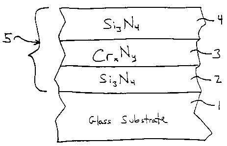
[0023] Figure 1 is a side cross sectional view of a coated article according
to an
example embodiment of this invention. The coated article includes at least
substrate 1
(e.g., clear, green, bronze, grey, blue, or blue-green glass substrate from
about 1.0 to
12.0 mm thick), first optional dielectric layer 2 (e.g., of or including
silicon nitride (e.g.,
Si;Nø), tin oxide, or some other suitable dielectric), infrared (IR)
reflecting layer 3
comprising, consisting essentially of, or consisting of chromium nitride
(Cr~Ny), and
second dielectric layer 4 (e.g., of or including silicon nitride (e.g.,
Si;N~.), tin oxide, or
some other suitable dielectric. In certain example embodiments of this
invention,
coating 5 does not include any metallic IR reflecting layer such as Ag or Au.
In such
embodiments, chromium nitride IR reflecting layer 3 may be the only IR
reflecting
layer in coating 5. In certain example embodiments of this invention, chromium
nitride
IR reflecting layer 3 does not contact any metal IR reflecting layer.
[0024] In certain example embodiments of this invention, IR reflecting layer 3
is
substantially free of Ni (i.e., contains no more than about 10 % Ni, more
preferably no
more than 5 % Ni, even more preferably no more than 1 % Ni, and most
preferably no
more than 0.01 % Ni).
(0025] Overall coating 5 includes at least layers 2-4. It is noted that the
terms
"oxide" and "nitride" as used herein include various stoichiometries. For
example, the
term silicon nitride includes stoichiometric Si;N~, as'well as non-
stoichiometric silicon
nitride such as Si-rich silicon nitride. Layers 2-4 may be deposited on
substrate 1 via
magnetron sputtering, or via any other suitable technique in different
embodiments of
this invention.
[0026] In certain example embodiments of this invention, IR~reflecting layer 3
is
sputter-deposited as chromium nitride. The stoichiometry of this layer as
deposited
may be represented, in certain example embodiments, by Cr~Ny, where the ratio
y/x
(i.e., the ratio of N to Cr) is from 0.25 to 0.7, even more preferably from
0.3 to 0.6, still
more preferably from 0.45 to 0.55. For purposes of example only, chromium
nitride in
the form of Cr2N translates into a y/x ratio of 1/2 (i.e., 0.5). It has
surprisingly been
found that the aforesaid y/x ratio ranges for nitrides of chromium are
particularly
beneficial with respect to coating characteristics such as durability and
optical
CA 02500308 2005-03-21
WO 2004/070072 PCT/US2004/001526
8
performance. For instances, nitriding of Cr in amounts greater than this
(approaching
CrN where yJx = 1) may result in less chemical resistance of coating 5 and/or
poor
adhesion to silicon nitride especially after HT. In other words, if the y/x
ratio is greater
than the aforesaid range(s), durability degrades in certain instances.
[0027] While Fig. 1 illustrates coating 5 in a manner where Cr,~Ny layer 3 is
in
direct contact with dielectric layers 2 and 4, and wherein CrxNy layer 3 is
the only IR
reflecting layer in the coating, the instant invention is not so limited.
Other layers)
may be provided between layers 2 and 3 (and/or between layers 3 and 4) in
certain
other embodiments of this invention. Moreover, other layers) may be provided
between substrate 1 and layer 2 in certain embodiments of this invention;
and/or other
layers) may be provided on substrate 1 over layer 4 in certain embodiments of
this
invention. Thus, while the coating 5 or layers thereof is/are "on" or
"supported by"
substrate 1 (directly or indirectly), other layers) may be provided
therebetween. Thus,
for example, the layer system 5 and layers thereof shown in Fig. 1 are
considered "on"
the substrate 1 even when other layers) may be provided therebetween (i.e.,
the terms
"on" and "supported by" as used herein are not limited to directly
contacting).
[0028] Surprisingly, it has been found that the use of CrxNy in layer 3 (as
opposed to NiCr) results in a coated article having: (a) improved corrosion
resistance
with respect to acid such as HCI; (b) improved mechanical durability; and (c)
improved
color stability upon heat treatment (i.e., lower DE* value(s)).
[0029] In certain example embodiments of this invention, dielectric anti-
reflection layers 2 and/or 4 each may have an index of refraction "n" of from
about 1.5
to 2.5, more preferably from 1.9 to 2.3. In embodiments of this invention
where layers
2 and/or 4 comprise silicon nitride (e.Q., Si;N~), sputtering targets
including Si
employed to form these layers may or may not be admixed with up to 6-
20°Io by weight
aluminum andlor stainless steel (e.g. SS#316), with about this amount then
appearing in
the layers so formed.
[0030] While Fig. 1 illustrates a coated article according to an embodiment of
this invention in monolithic form, Fig. 2 illustrates the coating or layer
system 5 of Fig.
CA 02500308 2005-03-21
WO 2004/070072 PCT/US2004/001526
9
1 being utilized on surface #? of an IG (insulating glass) window unit. In
Fig. 2, the
two glass substrates (e.g., float glass 2 mm to 12 mm thick) l, 7 are sealed
at their
peripheral edges by a conventional sealant and/or spacer (not shown) and may
be
provided with a conventional desiccant strip (not shown). The panes are then
retained
in a conventional window or door retaining frame. By sealing the peripheral
edges of
the glass sheets and replacing the air in insulating space (or chamber) 9 with
a gas such
as argon, a high insulating value IG unit is formed as illustrated in Fig. 2.
Optionally,
insulating space 9 may be at a pressure less than atmospheric pressure in
certain
alternative embodiments, although this of course is not necessary in all IG
embodiments. In IG embodiments, coating 5 from Fig. 1 may be provided on the
inner
wall of substrate 1 in certain embodiments of this invention,(as in Fig. 2),
andlor on the
inner wall of substrate 7 in other embodiments of this invention.
[0031] Turning back to Fig, l, while various thicknesses may be used
consistent
with one or more of the objects and/or needs discussed herein. According to
certain
non-limiting example embodiments of this invention, example thicknesses and
materials for the respective layers on the glass substrate 1 are as follows:
Table 1 (Example non-limiting thicknesses)
Layer Example Range (~) Preferred (A) Best (A)
silicon nitride (layer ?): 10-1,200 ~ ?0-1,000 ~ 50-900 t1
Cr;~Ny (layer 3): 50-700 ~ 100-500 t~ 100-300 t~
silicon nitride (layer 4): 50-900 ~ 100-500 ~ ' 200-400 A
[0032] In certain exemplary embodiments, the color stability with HT may
result
in substantial matchability between heat-treated and non-heat treated versions
of the
Boating or layer system. In other words, in monolithic and/or IG applications,
in certain
embodiments of this invention two glass substrates having the same coating
system
thereon (one HT after deposition and the other not HT) appear to the naked
human eye
to look substantially the same. Stated yet another way, the coated article has
good color
CA 02500308 2005-03-21
WO 2004/070072 PCT/US2004/001526
1~
stability upon HT.
[0033] The values) DE* is important in determining whether or not there is
matchability, or substantial color matchability upon HT, in the context of
certain
embodiments of this invention (i.e., the term DE* is important in determining
color
stability upon HT). Color herein is described by reference to the conventional
a*, b*
values. For example, the term Da* is indicative of how much color value a*
changes
due to HT.
[0034] The term ~E* (and DE) is well understood in the art and is reported,
along with various techniques for determining it, in ASTM 2244-93 as well as
being
reported in Hunter et. al., The Mea~aaremefat of Appearance, 2°d Ed.
Cptr. 9, page 162 et
seq. (John Wiley & Sons, 197). As used in the art, DE* (and 0E) is a way of
adequately expressing the change (or lack thereof) in reflectance and/or
transmittance
(and thus color appearance, as well) in an article after or due to HT. DE may
be
calculated by the "ab" technique, or by the Hunter technique (designated by
employing
a subscript "H"). 0E corresponds to the Hunter Lab L, a, b scale (or Lh, ah,
b,,).
Similarly, ~E* corresponds to the CIE LAB Scale L*, a*, b*. Both are deemed
useful,
and equivalent for the purposes of this invention. For example, as reported in
Hunter et.
al. referenced above, the rectangular coordinate/scale technique (CIE LAB
1976)
known as the L*, a*, b* scale may be used, wherein:
L* is (CIE 1976) lightness units
a* is (CIE 1976) red-green units
b* is (CIE 1976) yellow-blue units
and the distance ~E* between L*o a*o b*o and L*, a* 1 b* 1 is:
DE* = f (~L*)' + (~a*)' + (fib*)' } 1iz (1)
where:
~L* = L* 1- L*o (2)
CA 02500308 2005-03-21
WO 2004/070072 PCT/US2004/001526
11
Da* = a*, - a*o (3)
~b*=b*~ -b*o
where the subscript "o" represents the coating (or coated article) before heat
treatment
and the subscript "1" represents the coating (or coated article) after heat
treatment; and
the numbers employed (e.g., a*, b*, L*) are those calculated by the aforesaid
(CIE LAB
1976) L*, a*, b* coordinate technique. In a similar manner, 0E may be
calculated
using equation (1) by replacing a*, b*, L* with Hunter Lab values a~" b,,, Lh.
Also
within the scope of this invention and the quantification of ~E* are the
equivalent
numbers if converted to those calculated by any other technique employing the
same
concept of dE* as defined above.
[0035] After heat treatment (HT) such as thermal tempering, in certain example
embodiments of this invention coated articles have color characteristics as
follows in
Table 2. It is noted that subscript "G" stands for glass side reflective
color, subscript
"T" stands for transmissive color, and subscript "F" stands for film side
color. As is
I known in the art, glass side (G) means reflective color when viewed from the
glass side
(as opposed to the layer/film side) of the coated article. Film side (F) (not
Shawn in
Table 2) means reflective color when viewed from the side of the coated
article on
which the coating 5 is provided.
Table 2: ColorlOptical Characteristics due tolafter Heat Treatment
General Preferred Most Preferred
~E*G <= 5.0 <_ ~.0 <_
DE*T <= 5.0 <= 4.0 <= 3.0
a=go -6 to +6 -4 to +4 -3 to +3
b*G -30 to +25 -25 to +20 -?0 to +10
~a'~G <= 1.0 <= 0.7 <= 0.5
~b*G <= 1.5 <= 0.~ <= 0.5
CA 02500308 2005-03-21
WO 2004/070072 PCT/US2004/001526
12
DL*G <= 5 <= 3 <= 2
Tv;s (TY): 8-80% 10-50% 10-30%
RS (S2lsc~: < 250 < 150 < 110
[0036] Coated articles after HT herein may even have a ~E* value(s) (glass
side
reflective andlor transmissive) of no greater than 2.5, more preferably no
greater than
2.0, and sometimes even no greater than 1.8 in certain example embodiments of
this
invention. In certain example embodiments, coated articles after HT herein may
even
have a DE* values) (glass side reflective and/or transmissive) of no greater
than 1.5, or
even 1.2.
[0037] Figs. 3-5 illustrate various stoichiometries of chromium nitride layer
3
according to different embodiments of this invention. In particular, these
figures
illustrate various ratios of N to Cr (ratios y/x) in the chromium nitride
layer 3 as a
function of nitrogen gas flow during the sputtering process in which the layer
3 is
sputter-deposited. In these figures, the N and Cr atomic percentages (at. %)
were
determined using XFS. Additionally, it is noted that the correlation between
nitrogen
gas flows and the N to Cr ratio(s) was determined in accordance with the ILS
coater
used to deposit these samples since the flows were measured in this sputter
coater.
[0038] Fig. 3 is a graph plotting, during sputtering of a chromium nitride
layer,
nitrogen gas flow as a percentage of total gas flow (e.g., where Ar and N
gases were
used) vs. Cr, N atomic content in the resulting layer 3, illustrating
stoichiometry of
chromium nitride layers according to different embodiments of this,invention
as a
function of nitrogen gas flow. Fig. 4 is a graph plotting nitrogen gas flow as
a
percentage of total gas flow during sputtering of a chromium nitride layer vs.
the
resulting ratio y/x (given CrrNy) in the resulting chromium nitride layer
according to
different embodiments of this invention, thereby illustrating different
stoichiometries of
the layer as a function of the amount of nitrogen in the total sputtering gas
flow. Fig. 5
is a graph plotting nitrogen gas flow (in units of sccm) during sputtering of
a chromium
nitride layer vs. the resulting ratio y/x (given Cr,~Ny) in the resulting
chromium nitride
CA 02500308 2005-03-21
WO 2004/070072 PCT/US2004/001526
13
layer according to different embodiments of this invention, thereby
illustrating different
stoichiometries of the layer as a function of nitrogen gas flow during
sputtering.
[0039] As explained above, the best performance (balancing durability and
solar
performance) surprisingly occurs when the CrrNy layer 3 is characterized by a
N to Cr
ratio y/x of from 0.25 to 0.7 (even 0.25 to 0.9 in some instances), even more
preferably
from 0.3 to 0.6, still more preferably from 0.45 to 0.55.
[0040] For purposes of example only, a plurality of examples representing
different example embodiments of this invention are set forth below.
EXAMPLES 1-2
[0041] Examples 1-2 were monolithic coated articles (each ultimately annealed
and heat treated). The Si;N.~ layers 2 and 4 in each example were deposited by
sputtering a silicon target {doped with about 10% Al) in an atmosphere
including
nitrogen gas. The chromium nitride layer 3 in each example was deposited by
sputtering in an atmosphere including argon and nitrogen gas.
[0042] For Example l, the following sputtering process parameters were used in
depositing the coating. Line speed is in inches per minute (IPM), and gas (Ar
and N)
flows were in units of sccm:
TABLE 3: Example 1 Coating Process Parameters
Layer Power Voltage Line Speed # Passes Ar flow N flow
SiN layer 2: 1.0 kW 463 V 41.2 2 40 40
CrXNy layer 3: 1.0 kW 392 V 41.5 2 45 ' 15
SiN layer 4: 1.0 kW 462 V 41.2 7 40 40
[0043] For Example 2, the following sputtering process parameters were used in
depositing the coating. Again, line speed is in inches per minute (IPM), and
gas flows
were in units of sccm:
TABLE 4: Example 2 Coating Process Parameters
Layer Power Voltage Line Speed # Passes Ar flow N flow
CA 02500308 2005-03-21
WO 2004/070072 PCT/US2004/001526
14
SiN layer 2: 2.5 kW 501 44.5 8 40 55
V
Cr;~Ny layer 3: 1.0 kW 393 38.1 2 45 15
V
SiN layer 4: 2.5 kW 502 41.3 2 40 55
V
[0044] After being sputtered, Examples 1-2 had the following characteristics
after being sputtered (annealed and non-HT) (Ill. C, 2 degree observer):
Parameter Ex.l Ex.2
T,,;S (TY)(transmissive):22.5% 20.9%
a*T -0.9 -1.1
b*T -4.6 2.4
L=ax 54.5 52.8
RGY(glass side refl. 31.5% 18.5 %
%):
a*G: -2.2 -1.1
b=~G: -4.2 -19.0
L'~G: 62.9 50.1
RFY (film side refl. ?0.7% 34.7%
%):
a*F: 0.3 0.1
b*F: 24.4 17.6
L*F: 52.6 65.5
Tso~ (TS): 18% 18%
CA 02500308 2005-03-21
WO 2004/070072 PCT/US2004/001526
Shading Coefficient (SC): 0.39 0.41
SHGC: 0.33 0.35
Tu" (UV transmission): 20.3% 16.0%
RS (sheet resistance; ohms/sq.): 86.4 n/a
[0045] Each of Examples 1 and 2 had a layer stack as follows, set forth in
Table
6. The thicknesses and stoichiometries listed below in Table 6 far the
Examples 1-2 are
approximations and are not exact. The coating 5 for each Example is shown in
Fig. 1,
and thus includes layers 2, 3 and 4. The glass substrates were clear and about
6 mm
thick in each Example.
TABLE 6: Coatings in Examples
Example 1: Glass/Si;N~.(100 .A)/Cr;~NY(170 A)/Si3N~.(350 A)
Example 2: Glass/Si;N~(890 A)/CrYNy(185 A)/Si;N4(240 A)
[U04b] After being sputter coated, each of Examples 1 and 2 was then heat
treated for 10 minutes at about 625 degrees C. Table 7 below sets forth
certain color
stability characteristics of Examples 1-2 upon/after heat treatment (HT).
TABLE 7: Glass Side Refl. Color Stability Upon HT
Parameter Ex.l Ex.2
0E*G: 0.8 1.7
[0047] As can be seen from Table 7, Examples 1-2 were characterized by
excellent glass side reflective ~E* values. The low numbers associated with
these
values illustrate how little the optical characteristics of the coating
changed upon the
heat treatment. This is indicative of superior stability upon heat treatment
(e.g., thermal
tempering or the like).
[0048] For purposes of comparison, consider the following layer stack:
glass/Si;Na/NiCr/ Si3N:~, which has a glass side reflective ~E* value of above
5.0 after
CA 02500308 2005-03-21
WO 2004/070072 PCT/US2004/001526
16
heat treatment (HT) at 625 degrees C for ten minutes. The Examples 1-2 above
clearly
illustrate the comparative advantage of using chromium nitride, as opposed to
NiCr, for
the IR reflecting layer. A much lower glass side reflective ~E* value is
achievable
using chromium nitride. Moreover, durability may also be improved as explained
above.
EXAMPLES 3-5
[0049] As mentioned above, it has surprisingly been found that given CrXNy in
layer 3, a ratio y/x (i.e., the ratio of N to Cr) of from 0.25 to 0.9, even
more preferably
from 0.3 to 0.7, still more preferably from 0.3 to 0.6, is superior to other
ratios with
respect to durability and optical characteristics. Examples 3-5 set forth
below illustrate
how different CrXNy layers 3 were made in a sputter coater (by sputtering)
according to
different embodiments of this invention, in various manner which kept the
ratio y/x
within the range of from 0.25 to 0.9. Examples 3-5 were each sputtered onto
3mm
clear glass substrates, with no silicon nitride layers thereon. The atomic
percentages
were measured in the resulting chromium nitride layers from the examples via
XPS, as
was the ratio y/x (given CrrNy).
TABLE 8: Sputtering of Examples 3-5
Characteristic Example 3 Example 4 Example 5
Material: CrXNy CrXNy Cr;~Ny
Power (kW): 1 1 1
U (V): 397 399 402
Pressure (mTorr): 1.8 2.0 2.4
Ar flow (sccm): 45 45 45
N flow (sccm): 10 20 30
% N flow (N/N+Ar): 18.2 30.8 40.0
Cr atomic %: 74.4 62.8 56.2
N atomic %: 24.5 35.8 40.2
CA 02500308 2005-03-21
WO 2004/070072 PCT/US2004/001526
17
Ratio y/x: 0.33 0.57 0.7'2
[0050] It can be seen from Table 8 above numerous ways in which to sputter
deposit chromium nitride in a manner such that the y/x ratio of N to Cr is in
the desired
range. In certain embodiments of this invention, the Cr atomic % in layer 3 is
from 55
to 90%, more preferably from 60 to 85%, and even more preferably from 65 to
75%;
whereas the N atomic % in layer 3 is from 15 to 50%, more preferably from 20
to 40%,
.and most preferably from 24 to 36%. These atomic % amounts of Cr and N
surprisingly result in improve color stability with HT (i.e., low DE*) in
combination
with improved durability.
[0051] Accordingly, advantages associated with the use of chromium nitride as
a
IR reflecting layer include (a) improved corrosion resistance with respect to
acid such
as HCI; (b) improved mechanical performance such as better scratch resistance;
and/or
(c) improved thermal stability (i.e., lower ~E* value(s)). In certain
embodiments of
this invention, coated articles may or may not be heat treated.
[0052] Certain terms are prevalently used in the glass coating art,
particularly
when defining the properties and solar management characteristics of coated
glass.
Such terms are used herein in accordance with their well known meaning. For
example, as used herein:
[0053] Intensity of reflected visible wavelength light, i.e. "reflectance" is
defined
by its percentage and is reported as RAY (i.e. the Y value cited below in ASTM
E-308-
85), wherein "X" is either "G" for glass side or "F" for film side. "Glass
side" (e.g.
"G") means, as viewed from the side of the glass substrate opposite that on
which the
coating resides, while "film side" (i.e. "F") means, as viewed from the side
of the glass
substrate on which the coating resides.
[0054] Color characteristics are measured and reported herein using the CIE
LAB a*, b* coordinates and scale (i.e. the CIE a*b* diagram, Ill. CIE-C, 2
degree
observer). Other similar coordinates may be equivalently used such as by the
subscript
"h" to signify the conventional use of the Hunter Lab Scale, or Ill. CIE-C,
10° observer,
CA 02500308 2005-03-21
WO 2004/070072 PCT/US2004/001526
18
or the CIE LUV u~'v~ coordinates. These scales are defined herein according to
ASTM
D-2244-93 "Standard Test Method for Calculation of Color Differences From
Instrumentally Measured Color Coordinates" 9/15/93 as augmented by ASTM E-308-
85, Annual Book of ASTM Standards, Vol. 06.01 "Standard Method for Computing
the
Colors of Objects by 10 Using the CIE System" and/or as reported in IES
LIGHTING
HANDBOOK 1981 Reference Volume.
[005x] The terms "emittance" and "transmittance" are well understood in the
art
and are used herein according to their well known meaning. Thus, for example,
the
terms visible light transmittance (TY), infrared radiation transmittance, and
ultraviolet
radiation transmittance (T"~) are known in the art. Total solar energy
transmittance
(TS) is then usually characterized as a weighted average of these values from
300 to
2500 nm (UV, visible and near IR). With respect to these transmittances,
visible
transmittance (TY), as reported herein, is characterized by the standard CIE
Illuminant
C, 2 degree observer, technique at 380 - 720 nm; near-infrared is 720 - 2500
nm;
ultraviolet is 300 - 380 nm; and total solar is 300 - 2500 nm. For purposes of
emittance,
however, a particular infrared range (i.e. 2.500 - 40,000 nm) is employed.
[0056] Visible transmittance can be measured using known, conventional
techniques. For example, by using a spectrophotometer, such as a Perkin Elmer
Lambda 900 or Hitachi U4001, a spectral curve of transmission is obtained.
Visible
transmission is then calculated using the aforesaid ASTM 308/2244-93
methodology.
A lesser number of wavelength points may be employed than prescribed, if
desired.
Another technique for measuring visible transmittance is to employ a
spectrometer such
as a commercially available Spectrogard spectrophotometer manufactured by
Pacific
Scientific Corporation. This device measures and reports visible transmittance
directly.
As reported and measured herein, visible transmittance (i.e. the Y value in
the CIE
tristimulus system, ASTM E-308-85) uses the Ill. C.,2 degree observer.
[0057] Another term employed herein is "sheet resistance". Sheet resistance
(RS)
is a well known term in the art and is used herein in accordance with its well
known
meaning. It is here reported in ohms per square units. Generally speaking,
this term
refers to the resistance in ohms for any square of a layer system on a glass
substrate to
CA 02500308 2005-03-21
WO 2004/070072 PCT/US2004/001526
19
an electric current passed through the layer system. Sheet resistance is an
indication of
how well the layer or layer system is reflecting infrared energy, and is thus
often used
along with emittance as a measure of this characteristic. "Sheet resistance"
may for
example be conveniently measured by using a 4-point probe ohmmeter, such as a
dispensable 4-point resistivity probe with a Magnetron Instruments Corp. head,
Model
M-800 produced by Signatone Corp. of Santa Clara, California.
[0058] "Chemical durability" or "chemically durable" is used herein
synonymously with the term of art "chemically resistant" or "chemical
stability". For
example, chemical durability may be determined by boiling a sample of a coated
glass
substrate in about 500 cc of 5% HCl for one hour (i.e. at about 195°F).
Alternatively,
chemical durability may be determined by an NaOH boil which includes boiling a
sample of a coated glass substrate in a solution having a pH of about 12.2
that is a
mixture of water and NaOH (about 0.4% NaOH); the solution is available from
LabChem, Inc., Cat. No. LC 24270-4 (this is what is meant by NaOH boil
herein). The
NaOH boil may be carried out at a temperature of about 145 degrees F (Examples
above), or about 195 decrees F in other instances.
[0059] The terms "heat treatment" and "heat treating" as used herein mean
heating the article to a temperature sufficient to enabling thermal tempering,
bending,
and/or heat strengthening of the glass inclusive article. This definition
includes, for
example, heating a coated article to a temperature of at least about 580 or
600 decrees
C for a sufficient period to enable tempering. In some instances, the HT may
be for at
least about 4 ox 5 minutes.
[0060] Once given the above disclosure many other features,'modifications and
improvements will become apparent to the skilled artisan. Such other features,
modifications and improvements are therefore considered to be a part of this
invention,
the scope of which is to be determined by the following claims: