Note : Les descriptions sont présentées dans la langue officielle dans laquelle elles ont été soumises.
CA 02500725 2005-03-15
DOOR AND WINDOW SILL GASKET
FIELD OF THE INVENTION
[0001] The present invention generally relates to building products and,
S more particularly, pertains to a sealing gasket for doors and windows.
BACKGROUND OF THE INVENTION
[0002] One of the most common failure points for unwanted air and/or
moistuxe in a building envelope is around doors and windows. Controlling air
and/or moisture is a serious concern which may result in exterior and interior
damage if not prevented or corrected in a timely manner. Recent studies have
shown that the extent of such damage has run into millions of dollars
annually. In
addition, heat losses caused by air leakage around building openings have
taken on
new significance due to today's high energy costs. Sealing to date has been
imperfectly accomplished by caulking or using a putty-like compound around
openings between door and window frames to seal the gaps and prevent inward
seepage of au and/or water into the building. There is often a further pxoblem
with
bugs entering through the same gaps.
[0003] In the case of a door, the caulking is typically placed between a
threshold and the subfloor; but this does not stop moisture getting into the
subfloor
face. After a period of time, moistuxe from melting snow or driving rain leads
not
only to swelling, rotting and warpage of the subfloor and structural framing,
but
also racks the door frame out of square and ruins the finish Mooring above the
subffoor. Once this happens, the door will need constant adjustments and, more
than likely, the finish Mooring will need to be replaced. The moisture and
humidity
2S along with the drying and shrinking of lumber also crack the caulk so that
air,
water, mold and insects may infiltrate under the threshold into the building.
[0004] In window installations, caulking around the window has been the
known installation and application method. However, this has proven to be a
failed
system because over long term, the caulking cannot withstand the constant
-1-
CA 02500725 2005-03-15
.
expansion and contraction of the window itself or the substrate. Test studies
show
that after several years in operation, almost 100 percent of all windows
either
leaked through the window flange or the window itself. This water leakage
along
with water intrusion caused by precipitation leads to structural damage such
as
rotting of the window sills and mold.
[0005] Given these problems, there remains a need for an improved
sealing gasket for ensuring a weather-tight barrier for door and window
installations.
SLmrEVIARY OF THE INVENTION
[0006] It is a general object of the present invention to provide a door and
window sealing gasket .which overcomes the deficiencies of the prior art.
[0007] It is also an object of the present invention to provide a door and
window sealing gasket which is 100 percent waterproof and is mold and mildew
resistant.
[0008] It is another object of the present invention to provide a door and
window sealing gasket which stops unwanted air andlor, moisture and bug
infiltration and protects sills from rotting.
[0009) It is an additional object of the present invention to provide a
sealing gasket which helps prevent subffoors from swelling and structural
framing
from warping.
[Ot11.0] It is a further obiect of the present invention to provide a sealing
gasket~which helps stop moisture intrusion to~ the subfloor causing eventual
destruction to the finish flooring.
[0011] Still another object of the present invention is to provide a sealing
ZS gasket which is energy efficient to reduce monthly utility costs.
[0012] Yet a further object of the present invention is to provide a door
and window sealing gasket which is self adhering to a variety of surfaces such
as
concrete, wood and metal.
-2-
CA 02500725 2005-03-15
[0013] One other object of the present invention is to provide a door and
window sealing gasket which features an easy peel and stick application that
offers
a savings in labor costs.
[OOI4] An extra object of the present invention is to provide a door and
window sealing gasket employing a rubberized, watezproof, modified asphalt
vv~ith
a high degree of elongation.
[0015] It is another object of the present invention to provide a method of
supplying a sill gasket between a threshold and a subfloor.
[0016] It is also an object of the present invention to provide a method of
supplying a sill gasket between a window frame and a window framework defining
a window opening.
[0017] It is yet another object of the present invention to provide a door
and window sealing gasket which utilizes commercially available materials for
the
manufacture thereof.
[0018] In one aspect of the invention, a door and window sill gasket is
adapted to seal the frame of doors and windows against moisture, air and
insects.
The sill gasket includes a water resistant, compressible material having an
upper
surface, a lower surface, and at least one edge. The lower surface of the
water
resistant compressible material is attached to an adhesively-coated top face
of a
rubberized asphalt sealing membrane providing an air/water infiltration
barrier and
having an adhesively-coated Iower face covered by a removable release liner,
the
membrane including a flexible covered flange extending outwardly fromthe at
least one edge of the water resistant, compressible material.
[0019] In the door sill gasket, the flexible covered membrane includes a
silicon release liner removably attached to the top face of the membrane. In
the
window sill gasket, the flexible covered membrane includes a drain material
attached to the top face of the membrane. Also in the window sill gasket, the
upper
face of the water resistant compressible material is downwaxdly sloped towards
the
-3-
CA 02500725 2005-03-15
flange. The membrane in both the door and window sill gaskets is highly
elastic
and has an elongation of up to S00 percent.
[4020] In. another aspect of the invention, there is contemplated a method
of providing a sill gasket to prevent air and moisture infiltration between a
threshold and a subfloor located at the bottom of a pair of spaced apart
structural
members defining a door jam. The method includes the steps of providing a
water
resistant compressible material having an upper surface, a lower surface, and
at
least one edge, the lower surface of the compressible material being attached
to an
adhesively-coated top face of a rubberized asphalt sealing membrane providing
an
air/water infiltration barrier and having an adhesively-coated lower face
covered by
a removable release liner, the membrane including a flexible, covered flange
extending outwardly from the at least one edge of the compressible material;
removing the release liner from the lower face of the membrane and adhesively
securing the membrane with the attached compressible material horizontally
across
an entire length of the subfloor such that opposed ends of the membrane extend
vertically along and are adhesively attached to the inside surfaces of the
door j am
structural members with the flange of the membrane projecting forwardly from
the
subfloor; folding and adhesively applying the flange of the membrane to
respective
front surfaces of the subfloor and the door jam structural members; and
securing
the threshold to at Ieast the upper surface of tlae compressible material
overlying the
subflaor.
[0021] Still another aspect of the invention contemplates a method of
providing a sill gasket to create positive flow of water leaked into a window
away
therefrom and to prevent moisture infiltration between a window frame and a
framework having a top member, a bottom member and side members, each with a
front surface defining a window opening. The method includes the steps of
providing a water resistant compressible material having an upper surface, a
lower
surface and at least one edge, the upper surface of the compxessible material
sloping downwardly towards the at least one edge, the Iower surface of the
-4-
CA 02500725 2005-03-15
compressible material being attached to an adhesively-coated top face of a
rubberized asphalt sealing membrane providing an air/water infiltration
barrier and
having an adhesively coated lower face covered by a removable release liner,
the
membrane including a flexible, covered flange extending outwardly from the at
S least one edge of the compressible material and having a drain material
attached to
the top face of the membrane; removing the release liner from the lower face
of the
membrane and adhesively securing the membrane with the attached compressible
material and one portion of the membrane with the drain material along inner
surfaces of the bottom and side members of the window opening framework with a
remaining portion of the flange of the membrane projecting forwardly from the
bottom member of the window opening framework; folding and adhesively
applying the remaining portion of flange of the membxane with the drain.
material
to the front surface of the bottom member; setting the window frame in the
window
opening on top of the drain material and fastening the window frame to the
respective front surfaces of the top, bottom and side members of the
framework;
and applying a sealing tape over peripheral edges of the window frame along
the
top and side members of the framework.
[0022] Various other objects, features and advantages of the invention
will be made apparent from the following description taken together with the
drawings.
BRIEF DESCRIPTION OF THE DRAWINGS
[0023] The drawings illustrate the best mode presently contemplated of
carrying out the invention.
[0024] In the drawings:
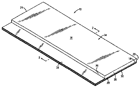
[0025] Fig. 1 is a perspective view of a sill gasket embodying the present
invention;
[0026] Fig. 2 is a sectional view taken on line 2-2 of Fig. l;
[0027] Fig. 3 is a fragmentary, perspective view of a partial installation
of the sill gasket in Fig. 1 on a door sill;
-5-
CA 02500725 2005-03-15
[0028] Fig. 4 is a view like Fig. 3 showing a finished instillation of the
sill gasket;
[0029] Fig. 5 is a view like Fig. 4 showing the installation of a threshold
over the sill gasket;
[0030] Fig. 6 is a perspective view of an alternative embodiment of the
sill gasket used in window installations;
[0031] Fig. 7 is a sectional view taken on line 7-7 of Fig. 6;
[0032] Fig. 8 is a fragmentary, perspective view of a partial installation
of the sill gasket of Fig. 6 on a window sill;
[0033] Fig. 9 is a view like Fig. 8 showing a finished installation of the
sill gasket;
[0034] Fig. 10 is a front view of a finished installation of the sill gasket
with the window installed;
[0035] Fig. 11 is a partial sectional view of Fig. 10;
[0036] Fig. 12 is an enlarged detail view of the drain material used in the
gasket of Fig. 6; and
[0037] Fig. 13 is. a sectional view taken on line 13-13 of Fig. I2.
DETAILED DESCRIPTION OF THE INDENTION
[0038] Referring now the drawings, Figs. 1-5 illustrate a sill gasket ZO for
sealing a door frame 12 against moisture, air and insect infiltration.
[0039] As seen in Figs. 1 and 2, the sill gasket 10 includes a layer of a
water resistant, compressible material 14 preferably constructed of closed
cell
polyethylene foam or similar material such as rubber or the like, having an
upper
surface 16, a lower surface 18, a front edge 20, a rear edge 22 and a pair of
opposed
side edges 24, 26. The lower surface 18 of the material 14 is attached to an
adhesively-coated top face of a peel and stick rubberized, waterproof,
modified
asphalt sealing membrane 28 for providing an air/water/insect infiltration
barrier.
The membrane 28 has an adhesively-coated lower face covered by a peel away
release liner 30, typically made of paper. The membrane 28 includes a
flexible,
-6-
CA 02500725 2005-03-15
covered gasket flange 32 which extends outwardly from the front edge ZO of the
material 14. Preferably, a silicon release liner 34 is removably attached to
an
adhesively-coated top face of the gasket flange 32. The rubberized,
waterproof,
modified asphalt membrane 28 preferably has a thickness of about 40 mil. Most
notably, the membrane 28 is highly elastic with an elongation of up to 500
percent.
The membrane 28 is commercially available from the Protecto Wrap Company of
Denver, Colorado.
[4440) Referring now to Figs. 3, 4 and 5, the door frame 12 includes a
horizontally extending, subfloor 36 extending transversely across the bottom
of a
pair of spaced apart, vertically extending, door jam or framing members 38,
40. A
sheathing material 42, such as OSB or plywood, is applied across the front of
the
door frame 12.
[0041 ) , In order to place the sill gasket 10 in the bottom of the door frame
12, an installer removes the paper release liner 30 from the lower face of the
membrane 28 and adhesively secures the membrane 28 with the foam 14 attached
and facing upward horizontally across an entire length of the door sill 36
such that
opposed ends of the membrane 28 extend vertically along and are attached to
short
lengths of the inside surfaces of the door jams 38, 40 with the flange 32 of
the
membrane 28 extending forwardly from the subfloor 36 as shown in Fig. 3. Next,
the installer folds the flange 32 downwardly and adhesively applies the flange
32 to
respective front surfaces of the subfloor 36 and door jams 38, 40 or the
sheathing
42 attached thereto as shown in Fig. 4. Once this is done, a conventional
threshold
44 is fastened, such as by mechanical fasteners or the like, at least to the
upper
surface 16 of the foam 14 and preferably also to the subfloor 36 itself as
shown in
Fig. 5.
[0042] Turning now to Figs. b and 7, there is shown an alternative
embodiment of the sill gasket identified by the reference numeral 46. This
sill
gasket design is used chiefly to prevent water and insect infiltration in
window
installation. In this version, the foam 14 has its rear edge 22 modified with
an
7_
CA 02500725 2005-03-15
upstanding finger 23, and its upper surface 16 sloped downwardly towards the
front
edge 20 for a reason to be explained below. In addition, the release liner 34
on the
top face of the flange 32 is replaced by a drain member~48. As seen in Figs.
12 and
13, the drain member 48 is preferably, a thin sheet made of a water resistant,
flexible plastic or other material having a plurality of raised dimples 49
which form
a series of flow paths 51 so that water will flow freely along the drain
member 48.
It should be understood, however, that the drain member 48 contemplates other
designs which promote free flow of water from the sloped surface 16 of foam
14.
(0043) Referring now to Figs. 8 and 9, a framework 50 includes a bottom
member or window sill 52 extending across the lower ends of a pair of spaced
side
members 54, 56, and a top member 58 connected transversely to the upper ends
of
the side members 54, 56. The four sided framework 50 defines an opening or a
window frame 60 having a window 62 as seen in Figs. 10 and 11. A sheathing
material 64 is applied across the front of the framework 50.
[0044) To position the sill gasket 46 at the bottom of the framework 50,
as seen in Fig. 8, the installer removes the paper release liner 30 from the
lower
face of the membrane 28, and adhesively secures the membrane 28 with the foam
14 attached along inner surfaces of the entire length of the window sill S2
and short
lengths of the side members 54, 56. During installation, a short length of the
flange
32 with drain member 4$ is attached to the front edge of bottom member 52 and
side members 54, 56, and the remainder of the flange 32 projects forwardly
from
the sill or bottom member 52, as best seen in Fig. 11. Next, the installer
folds the
flange 32 downwardly and adhesively applies the flange 32 to the front surface
or
sheathing material 64 adjacent sill 52 as seen in Fig. 10. The sill gasket 46
is fully
installed at this point such that the upper surface 16 of the foam 14 slopes
towards
the front of the framework 50 so as to direct any water which leaks from the
window along flow paths 51 of the drain member 48 and positively out of the
window opening. Next, the window frame 60 is positioned in the window opening
of the framework 50 so that a peripheral window frame flange 66 overlaps
marginal
_g_
CA 02500725 2005-03-15
portions of the top member 58, side members 54, 56, and the sheathing material
64
as illustrated in Fig. 10. The bottom of window frame 60 is conveniently
supported
on the drain member 48. The window frame 60 is held in place by inserting
mechanical fasteners 68 through the window flange 66 into the framework 50.
Finally, it is suggested that a sealing tape 70 having a removable release
Liner is
applied to overlap the window flange'66 and the sheathing material 64 along
the
front surfaces of the top member 58 and side members 54, 56.
[0045] With this construction, any moisture that leaks into the window
through window flange 66 or the window itself can be channeled with positive
flow
forwardly and outwardly by the pazticular downward slope of the foam 14 and be
quickly directed down and away from the window by the flow paths 51 of drain
member 48. Such moisture is prevented from escaping rearwardly by the finger
23
at the rear of foam 14 which acts as a backdam. Any moisture intrusion from
rain
or snow is prevented from entering the window by the gasket 46 and the sealing
tape 70.
[0046) Fig. 11 depicts the window installation of the sill gasket 46 in
cross section and shows the rear of the window sill 52 provided with drywall
72.
Window trim 74 may be placed between the rear of the window frame 60 and the
drywall 74. Also, a layer of Tyvek protective house wrap (not shown) may be
optionally placed over the sheathing material 64 before the sill gasket 46 is
applied.
[0047) When installing door sill gasket 10 or window sill gasket 46, it
should be appreciated that the tremendous elasticity of the membrane 28
enables an
installer to easily pull and position the flange 32 onto the sheathing
material 42 or
64 as desired. The membrane 28 has a particular construction which is air and
moisture impermeable and helps define a long lasting, effective sealing gasket
which is 100 percent waterproof, and is mold and mildew resistant. As a
result,
subfloors and sills are prevented from rotting, swelling and warping, finish
flooring
is not destroyed, and energy losses are abated with a noticeable savings in
energy
costs. In the case of the window sill gasket 46, the compressible material or
foam
-9-
. CA 02500725 2005-03-15
~ 14 adds to the versatility of enabling more or denser insulation to be
"chinked in"
around the window than can be done with a hard substrate. The sealing gasket
10
or 46 features a simple peel and stick application which contributes to a
further
savings in labor costs, and is adherent to a variety of materials including
wood,
concrete and metal.
[0048] While the invention has been described with reference to a
prefexred embodiment, those skilled in the art will appreciate that certain
substitutions, alterations and omissions may be made without departing from
the
spirit thereof. Accordingly, the foregoing description is meant to be
exemplary
only and should not be deemed limitative on the scope of the invention set
forth
with the following claims.
-10-