Note : Les descriptions sont présentées dans la langue officielle dans laquelle elles ont été soumises.
CA 02500835 2010-07-21
TRACTION SHEAVE ELEVATOR WITHOUT COUNTERWEIGHT
FIELD OF THE INVENTION
The present invention relates to an elevator.
BACKGROUND OF THE INVENTION
Particularly, the present invention relates to an
elevator without counterweight and, preferably, without
machine room. One of the objectives in elevator
development work is to achieve efficient. and economical
utilization of building space. In recent years, this
development work has produced various elevator solutions
without machine room, among other things. Good examples
of elevators without machine room are disclosed in
specifications European Patent No. 0 631 967 (Al) and
European Patent No. 0 631 968. The elevators described in
these specifications are fairly efficient in respect of
space utilization as they have made it possible to
eliminate the space required by the elevator machine room
in the building without a need to enlarge the elevator
shaft. In the elevators disclosed in these
specifications, the machine is compact at least in one
direction, but in other directions it may have much
larger dimensions than a conventional elevator machine.
In these basically good elevator solutions, the space
required by the hoisting machine limits the freedom of
choice in elevator lay-out solutions. Space is needed for
the arrangements required for the passage of the hoisting
ropes. It is difficult to reduce the space required by
the elevator car itself on its track and likewise the
space required by the counterweight, at least at a
reasonable cost and without impairing elevator
performance and operational quality. In a traction sheave
elevator without machine room, mounting the hoisting
machine in the elevator shaft is often difficult,
especially in a solution with machine above, because the
hoisting machine is a sizeable body of considerable
CA 02500835 2010-07-21
2
weight. Especially in the case of larger loads, speeds
and/or hoisting heights, the size and weight of the
machine are a problem regarding installation, even so
much so that the required machine size and weight have in
practice limited the sphere of application of the concept
of elevator without machine room or at least retarded the
introduction of said concept in larger elevators. In
modernization of elevators, the space available in the
elevator shaft often limits the area of application of
the concept of elevator without machine room. In many
cases, especially when hydraulic elevators are modernized
or replaced, it is not practical to apply the concept of
roped elevator without machine room due to insufficient
space in the shaft, especially in a case where the
hydraulic elevator solution to be modernized/replaced has
no counterweight. A disadvantage with elevators provided
with a counterweight is the cost of the counterweight and
the space it requires in the shaft. Drum elevators, which
are nowadays rarely used, have the drawbacks of requiring
heavy and complex hoisting machines with a high power
consumption.
SUMMARY OF THE INVENTION
The present invention is, thus, devised to achieve at
least one of the following objectives. On the one hand,
it is an aim the invention to develop the elevator
without machine room further so as to allow more
effective space utilization in the building and elevator
shaft than before. This means that the elevator should
permit of being installed in a fairly narrow elevator
shaft if necessary. On the other hand, it is an aim of
the invention to reduce the size and/or weight of the
elevator or at least its machine. One objective is to
achieve an elevator in which the hoisting rope of an
elevator with thin hoisting rope and/or a small traction
sheave has a good grip/contact on the traction sheave. A
CA 02500835 2010-07-21
3
further aim of the invention is to achieve an elevator
solution without counter weight without compromising on
the properties of the elevator.
The object of the invention should be achieved without
compromising the possibility of varying the basic layout
of the elevator.
According to an embodiment of the present invention,
there is provided an elevator, without counterweight, in
which elevator a hoisting machine engages a set of
hoisting ropes by means of a traction sheave, an elevator
car being at least partially supported by the hoisting
ropes, which serve as a means of moving the elevator car,
wherein the elevator car is suspended on the hoisting
ropes by means of at least one diverting pulley from
whose rim the hoisting ropes go upwards from both sides
and at least one diverting pulley from whose rim the
hoisting ropes go downwards from both sides of the
diverting pulley, and in which elevator the guide rails
are arranged on one side of the elevator car. Other
embodiments of the invention are characterized by what is
disclosed in the claims appended hereto. Some inventive
embodiments are also discussed in the description section
of the present application. The inventive content of the
application can also be defined differently than in the
claims presented below. The inventive content may also
consist of several separate inventions, especially if the
invention is considered in the light of expressions or
implicit sub-tasks or from the point of view of
advantages or categories of advantages achieved. In this
case, some of the attributes contained in the claims
below may be superfluous from the point view of separate
inventive concepts.
CA 02500835 2010-07-21
3a
By applying the invention, one or more of the following
advantages, among others, can be achieved:
- Using a small traction sheave, a very compact elevator
and/or elevator machine is achieved
- The small coated traction sheave used allows the weight
of the machine to be easily reduced even to about half
of the weight of the machines now generally used in
elevators without machine room. For example, in the
case of elevators designed for a nominal load below
1000 kg, this means machines weighing 100-150 kg or
even less. Via appropriate motor solutions and choices
of materials, it is even possible to achieve machines
having a weight below 100 kg or even as small as about
50 kg.
CA 02500835 2010-07-21
4
- A good traction sheave grip, which is achieved in
particular by using Double Wrap roping, and light-
weight components allow the weight of the elevator
car to be considerably reduced.
- A compact machine size and thin, substantially round
ropes permit the elevator machine to be relatively
freely placed in the shaft. Thus, the elevator solu-
tion of the invention can be implemented in a fairly
wide variety of ways in the case of both elevators
with machine above and elevators with machine below.
- The elevator machine can be advantageously placed
between the car and a shaft wall.
- All or at least part of the weight of the elevator
car can be carried by the elevator guide rails.
- In elevators applying the invention, a centric sus-
pension arrangement of the elevator car can be read-
ily achieved, thereby reducing the lateral support-
ing forces applied to the guide rails.
- Applying the invention allows effective utilization
of the cross-sectional area of the shaft.
- The invention reduces the installation time and to-
tal installation costs of the elevator.
- The elevator is economical to manufacture and in-
stall because many of its components are smaller and
lighter than those used before.
- The speed governor rope and the hoisting rope are
usually different in respect of their properties and
they can be easily distinguished from each other
during installation if the speed governor rope is
thicker than the hoisting ropes; on the other hand,
the speed governor rope and the hoisting ropes may
CA 02500835 2010-07-21
also be of identical structure, which will reduce
ambiguities regarding these matters in elevator de-
livery logistics and installation.
- The light, thin ropes are easy to handle, allowing
5 considerably faster installation.
- E.g. in elevators for a nominal load below 1000 kg,
the thin and strong steel wire ropes of the inven-
tion have a diameter of the order of only 3-5 mm,
although thinner and thicker ropes may also be used.
- With rope diameters of about 6 mm or 8 mm, fairly
large and fast elevators according to the invention
can be achieved.
- The traction sheave and the rope pulleys are small
and light as compared with those used in conven-
tional elevators.
- The small traction sheave allows the use of smaller
operating brakes.
- The small traction sheave reduces the torque re-
quirement, thus allowing the use of a smaller motor
with smaller operating brakes.
- Because of the smaller traction sheave, a higher ro-
tational speed is needed to achieve a given car
speed, which means that the same motor output power
can be reached by a smaller motor.
- Either coated or uncoated ropes can be used.
- it is possible to implement the traction sheave and
the rope pulleys in such a way that, after the coat-
ing on the pulley has been worn out, the rope will
bite firmly on the pulley and thus a sufficient grip
between rope and pulley in this emergency is main-
tained.
CA 02500835 2010-07-21
6
- The use of a small traction sheave makes it possible
to use a smaller elevator drive motor, which means a
reduction in drive motor acquisition/manufacturing
costs.
- The invention can be applied in gearless and geared
elevator motor solutions.
- Although the invention is primarily intended for use
in elevators without machine room, it can also be
applied in elevators with machine room.
- In the invention a better grip and a better contact
between the hoisting ropes and the traction sheave
are achieved by increasing the contact angle between
them.
- Due to the improved grip, the size and weight of the
car can be reduced.
- The space saving potential of the,elevator of the
invention is increased considerably as the space re-
quired by the counterweight is at least partially
eliminated.
- In the elevator of the invention, a lighter and
smaller machine and/or motor can be used
- As a result of the lighter and smaller elevator sys-
tem, energy savings and at the same time cost sav-
ings are achieved.
- The placement of the machine in the shaft can be
relatively freely chosen as the space required by
the counterweight and counterweight guide rails can
be used for other purposes
- By mounting at least the elevator hoisting machine,
the traction sheave and a rope sheave functioning as
a diverting pulley in a complete unit., which is fit-
CA 02500835 2010-07-21
7
ted as a part of the elevator of the invention, con-
siderable savings in installation time and costs
will be achieved.
- In the elevator solution of the invention, it is
possible to dispose all ropes in the shaft on one
side of the elevator car; for example, in the case
of rucksack type solutions, the ropes can be ar-
ranged to run behind the elevator car in the space
between the elevator car and the back wall of the
elevator shaft.
- The invention makes it easy to implement scenic-type
elevator solutions as well.
- Since the elevator solution of the invention does
not necessarily comprise a counterweight, it is pos-
sible to implement elevator solutions in which the
elevator car has doors in several walls, in an ex-
treme case even in all the walls of the elevator
car. In this case, the elevator car guide rails are
disposed at the corners of the elevator car.
- The elevator solution of the invention can be imple-
mented with several different machine solutions.
- The suspension of the car can be implemented using
almost any suitable suspension ratio.
The primary area of application of the invention is
elevators designed for the transportation of people
and/or freight. A typical area of application of the
invention is in elevators whose speed range is about
1.0 m/s or below but may also be higher. For example,
an elevator having a traveling speed of 0.6 m/s is
easy to implement according to the invention.
In both passenger and freight elevators, many of the
advantages achieved through the invention are pro-
CA 02500835 2010-07-21
8
nouncedly brought out even in elevators for only 2-4
people, and distinctly already in elevators for 6-8
people (500 - 630 kg).
In the elevator of the invention, normal elevator
hoisting ropes, such as generally used steel ropes,
are applicable. In the elevator, it is possible to use
ropes made of artificial materials and ropes in which
the load-bearing part is made of artificial fiber,
such as e.g. so-called "aramid ropes", which have re-
cently been proposed for use in elevators. Applicable
solutions include also steel-reinforced flat ropes,
especially because they allow a small deflection ra-
dius. Particularly well applicable in the elevator of
the invention are elevator hoisting ropes twisted e.g.
from round and strong wires. From round wires, the
rope can be twisted in many ways using wires of dif-
ferent or equal thickness. In ropes well applicable in
the invention, the wire thickness is below 0.4 mm on
an average. Well applicable ropes made from strong
wires are those in which the average wire thickness is
below 0.3 mm or even below 0.2 mm. For instance, thin-
wired and strong 4 mm ropes can be twisted relatively
economically from wires such that the mean wire thick-
ness in the finished rope is in the range of 0.15 ...
0.25 mm, while the thinnest wires may have a thickness
as small as only about 0.1 mm. Thin rope wires can
easily be made very strong. In the invention, rope
wires having a strength greater than 2000 N/mm2 are
used. A suitable range of rope wire strength is 2300-
2700 N/mm2. In principle, it is possible to use rope
wires having a strength of up to about 3000 N/mm2 or
even more.
The elevator of the invention is preferably an eleva-
tor without machine room, in which elevator the hoist-
ing machine engages the hoisting ropes by means of a
CA 02500835 2010-07-21
9
traction sheave, the elevator car being at least
partially supported by said hoisting ropes, which serve
as transmission means for moving the elevator car. The
elevator car is connected to the hoisting ropes via at
least one diverting pulley from the rim of which the
hoisting ropes go upwards from both sides of the
diverting pulley, and at least one diverting pulley from
the rim of which the hoisting ropes go downwards from
both sides of the diverting pulley, and in which elevator
the traction sheave engages the rope portion between
these diverting pulleys By increasing the contact angle
by means of a rope sheave functioning as a diverting
pulley, the grip between the traction sheave and the
hoisting ropes can be increased. In this way, the car can
be made lighter and its size can be reduced, thus
increasing the space saving potential of the elevator. A
contact angle of over 180 between the traction sheave
and the hoisting rope is achieved by using one or more
diverting pulleys.
BRIEF DESCRIPTION OF THE DRAWINGS
In the following, the invention will be described in
detail by the aid of a few examples of its embodiments
with reference to the attached drawings, wherein
Fig. 1 presents a diagram representing a traction
sheave elevator according to the invention,
Fig. 2. presents a diagram representing a second traction
sheave elevator according to the invention,
Fig. 3. presents a diagram representing a third traction
sheave elevator according to the invention,
Fig. 4 presents a diagram representing a traction sheave
elevator according to the invention,
CA 02500835 2010-07-21
Fig. 5 presents a diagram representing a traction sheave
elevator according to the invention,
Fig. 6 presents a traction sheave applying the invention,
5 Fig. 7 illustrates a coating solution according to the
invention,
Fig. 8a presents a steel wire rope used in the invention,
Fig. 8b presents a second steel wire rope used in the
invention,
10 Fig. 8c presents a third steel wire rope used in the
invention,
Figures 9 present some traction sheave roping
arrangements according to the invention,
Fig. 10 presents an embodiment of the invention, Fig. 11
presents an embodiment of the invention,
Fig. 12 presents a diagram of a rope sheave placement
according to the invention and
Fig. 13 presents an embodiment of the invention.
DETAILED DESCRIPTION OF THE INVENTION
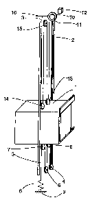
Fig. 1 presents a diagrammatic illustration of the
structure of the elevator. The elevator is preferably an
elevator without machine room, with a drive machine 10
placed in the elevator shaft. The elevator shown in the
figure is a traction sheave elevator without
counterweight and with machine above. The passage of the
hoisting ropes 3 of the elevator is as follows: One end
of the ropes is immovably fixed to an anchorage. 16 in
the upper part of the shaft, from where the ropes 3 go
further to a diverting pulley 15 placed in the up-
CA 02500835 2010-07-21
11
per part of the shaft and from which diverting pulley
15 the ropes go further to a diverting pulley 13
placed above the elevator car, from which diverting
pulley 13 the ropes go further to upwards to the trac-
tion sheave 11 of the drive machine 10, passing around
it along the rope grooves of the traction sheave. From
the traction sheave 11, the ropes 3 go further down-
wards past the elevator car 1 moving along the eleva-
tor guide rails 2 to a diverting pulley 4 placed in
the lower part of the shaft, going further from di-
verting pulley 4 to a diverting pulley below the ele-
vator car, from where the ropes 3 go further to a di-
verting pulley 6 in the lower part of the elevator
shaft and then further to a diverting pulley 7 below
the elevator car, from where the ropes 3 go further to
an anchorage 9 in the lower part of the elevator
shaft, to which the other end of the ropes 3 is im-
movably secured. At the lower anchorage of the hoist-
ing rope 3 there is also rope tensioning element 8, by
means of which the rope tension can be adjusted. The
tensioning element 8 may be e.g. a spring or a weight
hanging freely at the end of the rope or some other
appropriate tensioning element solution. In a pre-
ferred case, the drive machine 10 may be fixed e.g. to
a car guide rail, and the diverting pulley 15 in the
upper part of the shaft is mounted on the beams in the
upper part of the shaft, which are fastened to the car
guide rails 2. The diverting pulleys 5,7,13,14 on the
elevator car are mounted on beams above and below the
car. The diverting pulleys in the lower part of the
shaft are preferably mounted on the shaft floor. In
Fig. 1, the traction sheave engages the rope portion
between diverting pulleys 13 and 5, which is a prefer-
able solution according to the invention.
The drive machine 10 placed in the elevator shaft is
preferably of a flat construction, in other words, the
CA 02500835 2010-07-21
12
machine has a small thickness dimension as compared
with its width and/or height, or at least the machine
is slim enough to be accommodated between the elevator
car and a wall of the elevator shaft. The machine may
also be placed differently, e.g. by disposing the slim
machine partly or completely between an imaginary ex-
tension of the elevator car and a shaft wall. In the
elevator of the invention, it is possible to use a
drive machine 10 of almost any type and design that
fits into the space intended for it. For example, it
is possible to use a geared or a gearless machine. The
machine may be of a compact and/or flat size. In the
suspension solutions according to the invention, the
rope speed is often high as compared to the speed of
the elevator, so it is possible to use even unsophis-
ticated machine types as the basic machine solution.
The elevator shaft is advantageously provided with
equipment required for the supply of power to the mo-
tor driving the traction sheave 11 as well as equip-
ment needed for elevator control, both of which can be
placed in a common instrument panel 12 or mounted
separately from each other or integrated partly or
completely with the drive machine 10. A preferable so-
lution is a gearless machine comprising a permanent
magnet motor. The drive machine may be fixed to a wall
of the elevator shaft, to the ceiling, to a guide rail
or to some other structure, such as a beam or frame.
In the case of an elevator with machine below, a fur-
ther possibility is to mount the machine on the bottom
of the elevator shaft. Fig. 1 illustrates a preferred
suspension solution in which the suspension ratio of
the diverting pulleys above the elevator car and the
diverting pulleys below the elevator car is the same
4:1 suspension in both cases. Other suspension solu-
tions can also be used to implement the invention. The
elevator presented in the figure has automatic tele-
scoping doors, but other types of automatic doors or
CA 02500835 2010-07-21
13
turning doors may also be used within the framework of
the invention. The elevator of the invention can also
be implemented as a solution comprising a machine
room, or the machine may be mounted to be movable to-
gether with the elevator. In the invention, the di-
verting pulleys connected to the elevator car may be
preferably mounted on one and the same beam, which
supports both the diverting pulleys above the car and
the diverting pulleys below the car. This beam may be
fitted on top of the car, on the side of the car or
below the car, on the car frame or in some other ap-
propriate place in the car structure. The diverting
pulleys may also be fitted each one separately in ap-
propriate places on the car and in the shaft.
Fig. 2 presents a diagram representing another trac-
tion sheave elevator according to the invention. In
this elevator, the ropes go upward from the machine.
This type of elevator is generally a traction sheave
elevator with machine below. The elevator car 201 is
suspended on the hoisting ropes 203 of the elevator.
The elevator drive machine unit 210 is mounted in the
elevator shaft, preferably in the lower part of the
shaft. The elevator car 201 moves in the elevator
shaft along an elevator guide rail 202 guiding it.
In Fig. 2, the hoisting ropes run as follows: One end
of the ropes is fixed to an anchorage 216 in the upper
part of the shaft, from where it-goes downward to a
diverting pulley 213, from which the ropes go further
upward to a first diverting pulley 215 mounted in the
upper part of the shaft and from diverting pulley 215
to a diverting pulley 214 on the elevator car 201,
from where it returns to a diverting pulley 219 in the
upper part of the shaft. From diverting pulley 219,
the hoisting ropes go further to the traction sheave
211 driven by the drive machine 210. From the traction
CA 02500835 2010-07-21
14
sheave, the ropes go again upwards to a diverting pul-
ley 204 mounted below the car, and having wrapped
around it the hoisting ropes run via a diverting pul-
ley 220 mounted in the lower part of the elevator
shaft back to a second diverting pulley 205 below the
car, from where the ropes go further to an anchorage
209 in the lower part of the elevator shaft, where the
other end of the hoisting ropes is fixed. A rope ten-
sioning element 208 is also provided at the lower rope
anchorage. The elevator presented in Fig. 2 is a trac-
tion sheave elevator with machine below, in which the
suspension ratio both above and below the car is 4:1.
In addition, a smaller shaft space is needed above or
below the elevator car because the rope sheaves used
as diverting pulleys have small diameters as compared
with earlier solutions, depending on how the rope
sheaves are mounted on the elevator car and/or the
frame of the elevator car.
Fig. 3 presents a diagrammatic illustration of the
structure of an elevator according to the invention.
The elevator is preferably an elevator without machine
room, with a drive machine 310 placed in the elevator
shaft. The elevator shown in Fig. 3 is a traction
sheave elevator with machine above, in which the sus-
pension ratio above and below the elevator car is 6:1.
The passage of the hoisting ropes 303 of the elevator
is as follows: One end of the ropes 303 is immovably
fixed to an anchorage 316 in the upper part of the
shaft, from where the ropes run downwards to a divert-
ing pulley 315 mounted at the side of the elevator
car, from where the ropes run further to the upper
part of the elevator shaft, passing around a diverting
pulley 320, from which the ropes 303 go further down-
wards to diverting pulley 314, from which they return
downwards to diverting pulley 313. Via the rope
grooves of diverting pulley 313, the hoisting ropes
CA 02500835 2010-07-21
run further upwards to the traction sheave 311 of the
drive machine 310, passing around the traction sheave
along the rope grooves on the sheave. From the trac-
tion sheave 311, the ropes 303 run further downwards
5 to diverting pulley 322, wrapping around it along the
rope grooves of the diverting pulley and then return-
ing back up to the traction sheave 311, over which the
ropes run in the traction sheave rope grooves. From
the traction sheave 311, the ropes 303 go further
10 downwards via the rope grooves of diverting pulley 322
to a diverting pulley 307 placed in the lower part of
the elevator shaft, from where they go further to the
elevator car 301 moving along the car guide rails 302
of the elevator and to a diverting pulley 306 mounted
15 at its lower edge. The ropes are passed between the
diverting pulleys 318,319 in the lower part of the
elevator shaft and the diverting pulleys 306,305,304
in the lower part of the elevator car as many times as
necessary to achieve the same suspension ratio for the
portion above the elevator car and the portion below
the car. After this, the rope goes downwards to an an-
chorage element 308, e.g. a weight, which functions as
a rope tensioning element hanging freely at the other
end of the rope. In the case presented in the figure,
the hoisting machine and the diverting pulleys are
preferably all placed on one and the same side of the
elevator car. This solution is particularly advanta-
geous in the case of a rucksack elevator solution, in
which case the above-mentioned components are disposed
behind the elevator car, in the space between the back
wall of the elevator car and the back wall of the
shaft. In a rucksack solution like this, the elevator
guide rails 302 may preferably be disposed e.g. in the
frontmost part of the elevator car at the sides of the
elevator car/elevator car frame. The roping arrange-
ment between the traction sheave 311 and the diverting
pulley 322 is referred to as Double Wrap roping,
CA 02500835 2010-07-21
16
wherein the hoisting ropes are wrapped around the
traction sheave two and/or more times. In this way,
the contact angle can be increased in two and/or more
stages. For example, in the embodiment presented in
Fig. 3, a contact angle of 180 + 180 , i.e. 360 be-
tween the traction sheave 311 and the hoisting ropes
303 is achieved. The Double Wrap roping presented in
the figure can also be arranged in another way, e.g.
by placing the diverting pulley on the side of the
traction sheave, in which case, as the hoisting ropes
pass twice around the traction sheave, a contact angle
of 180 + 90 = 270 is achieved, or by placing the
traction sheave in some other appropriate location. A
preferable solution is to dispose the traction sheave
311 and the diverting pulley 322 in such a way that
the diverting pulley 322 will also function as a guide
of the hoisting ropes 303 and as a damping wheel. An-
other advantageous solution is to build a complete
unit comprising both an elevator drive machine with a
traction sheave and one or more diverting pulleys with
bearings in a correct operating angle relative to the
traction sheave to increase the contact angle. The op-
erating angle is determined by the roping used between
the traction sheave an the diverting pulley/ diverting
pulleys, which defines the way in which the mutual po-
sitions and angle between the traction sheave and di-
verting pulley/diverting pulleys relative to each
other are fitted in the unit. This unit can be mounted
in place as a unitary aggregate in the same way as, a
drive machine. The drive machine may be fixed to a
wall of the elevator shaft, to the ceiling, to a guide
rail or guide rails or to some other structure, such
as a beam or frame. in Double Wrap roping, when the
diverting pulley is of substantially equal size with
the traction sheave, the diverting pulley can also
function as a damping wheel. In this case, the ropes
going from the traction sheave to the counterweight
CA 02500835 2010-07-21
17
and to the elevator car are passed via the rope
grooves of the diverting pulley and the rope deflec-
tion caused by the diverting pulley is very small. It
could be said that the ropes coming from the traction
sheave only touch the diverting pulley tangentially.
Such tangential contact serves as a solution damping
the vibrations of the outgoing ropes and it can be ap-
plied in other roping solutions as well.
Fig. 4 presents a diagrammatic illustration of the
structure of a fourth elevator according to the inven-
tion. The elevator is preferably an elevator without
machine room, with a drive machine 410 placed in the
elevator shaft. The elevator shown in Fig. 4 is a
traction sheave elevator with machine above and having
a suspension ratio of 7:1 above and below the elevator
car, which is a very advantageous implementation of
the invention in respect of suspension ratio. The pas-
sage of the hoisting ropes is mainly similar to that
in Fig. 3, but in this figure the starting point of
the hoisting ropes 403 is on the elevator car 401, to
which the rope is substantially immovably secured.
With this arrangement, an odd suspension ratio is
achieved for the portion above the elevator car. A
further difference from Fig. 3 is that the number of
diverting pulleys mounted in the upper part of the
elevator shaft larger by one than in Fig. 3. The pas-
sage of ropes to the hoisting machine 410 follows the
same principle as in Fig. 3. From the hoisting machine
410, hoisting rope runs between the diverting pulleys
407,418,419,423 in the lower part of the elevator
shaft and the diverting pulleys 406,405,404 mounted
below the elevator car on the same principle as in
Fig. 3. In the portion below the elevator car, the
same suspension ratio, i.e. an odd suspension ratio of
7:1, is achieved by fixing the ropes to an anchorage
425 on the elevator car 401. Placed at this fixing
CA 02500835 2010-07-21
18
point is also a rope tensioning element. In Fig. 4
there is also a difference from Fig. 3 in respect of
the roping between the traction sheave 411 and the di-
verting pulley 422. The roping arrangement presented
in Fig. 4 can also be called.X Wrap (XW) roping. Pre-
viously known concepts are Double Wrap (DW) roping,
Single Wrap (SW) roping and Extended Single Wrap (ESW)
roping. In X Wrap roping, the hoisting ropes are
caused to wrap around the traction sheave 411 with a
large contact angle. For example, in the case pre-
sented in Fig. 4, a contact angle well over 180 , i.e.
about 270 between the traction sheave 411 and the
hoisting ropes is achieved. X Wrap roping presented in
the figure can also be arranged in another way, e.g.
by providing two diverting pulleys at appropriate po-
sitions near the drive machine. In Fig. 4, diverting
pulley 422 has been fitted in place at an angle rela-
tive to the traction sheave 807 such that the ropes
will run crosswise in a manner known in itself so that
the ropes are not damaged. In this figure, the passage
of the hoisting ropes from diverting pulley 413 is so
arranged that ropes run via the rope grooves of di-
verting pulley 422 to the traction sheave 411 of the
drive machine 410, wrapping around it-along the trac-
tion sheave rope grooves. From the traction sheave
411, the ropes 403 go further downwards, passing
crosswise with the ropes going upwards and further
downwards via the rope grooves of the diverting pulley
to diverting pulley 407.
Fig. 5 presents 1 a diagram illustrating the structure
of an elevator according to the invention. The eleva-
tor is preferably an elevator without machine room,
with a drive machine 510 placed in the elevator shaft.
The elevator shown in the figure is a traction sheave
elevator with machine above and with a 9:1 suspension
ratio both above and below the elevator car. The pas-
CA 02500835 2010-07-21
19
sage of the hoisting ropes 503 of the elevator is as
follows: One end of the ropes is substantially immova-
bly fixed relative to the elevator car at a fixing
point 530 so as to be movable with the elevator car,
from where the ropes go upwards to a diverting pulley
525 in the upper part of the shaft, from which pulley
they run further in the manner described above between
diverting pulleys 525,513,524,514,520,515,521,526, and
from which diverting pulleys the ropes 503 go further
to the traction sheave 511 of the drive machine 510,
passing around it along the rope grooves of the trac-
tion sheave. From the traction sheave 511, the hoist-
ing ropes 303 go further downwards, passing crosswise
with the ropes going upwards, to diverting pulley 522,
passing around it along the rope grooves of the di-
verting pulley 522. From diverting pulley 522, the
ropes 503 go further downwards to a diverting pulley
528 in the lower part of the elevator shaft. The ropes
then run further from diverting pulley 528 upwards be-
tween the diverting pulleys 504,505,506,507 in the
lower part of the elevator car and the diverting pul-
leys 528,527,526,519,518 in the lower part of the ele-
vator shaft in the manner described in connection with
the preceding figures. in Fig. 5, an odd suspension
ratio is achieved below the elevator car as well by
having the hoisting rope fixed substantially immovably
relative to the elevator car at a fixing point 531, to
which fixing point is also fitted a mounting element.
The roping arrangement used between the traction
sheave 511 and diverting pulley 522 is called Extended
Single Wrap roping. In Extended Single Wrap roping,
the hoisting ropes is caused to wrap around the trac-
tion sheave with a larger contact angle by using a di-
verting pulley. For example, in the case illustrated
in Fig. 5, the contact angle between the traction
sheave 511 and the hoisting ropes 503 is well over
180 , i.e. about 270 . The Extended Single Wrap roping
CA 02500835 2010-07-21
presented in Fig. 5 can also be arranged in another
way, e.g. by disposing the traction sheave and the di-
verting pulley in a different manner relative to each
other, for example the other way round with respect to
5 each other than in Fig. 5. The diverting pulley 522 is
fitted in place at an angle relative to the traction
sheave 511 such that the ropes pass crosswise in a
manner known in itself so that the ropes are not dam-
aged.
10 Fig. 6 presents a partially sectioned view of a rope
sheave 600 applying the invention. The rope grooves
601 are under a coating 602 on the rim 606 of the rope
sheave. Provided in the hub of the rope sheave is a
space 603 for a bearing used to mount the rope sheave.
15 The rope sheave is also provided with holes 605 for
bolts, allowing the rope sheave to be fastened by its
side to an anchorage in the hoisting machine 10, e.g.
to a rotating flange, to form a traction sheave 11, so
that no bearing separate from the hoisting machine is
20 needed. The coating material used on the traction
sheave and the rope sheaves may consist of rubber,
polyurethane or a corresponding elastic material that
increases friction. The material of the traction
sheave and/or rope sheaves may also be so chosen that,
together with the hoisting rope used, it forms a mate-
rial pair such that the hoisting rope will bite into
the pulley after the coating on the pulley has been
worn out. This ensures a sufficient grip between the
rope sheave 600 and the hoisting rope 3 in an emer-
gency where the coating 602 has been worn out from the
rope sheave 600. This feature allows the elevator to
maintain its functionality and operational reliability
in the situation referred to. The traction sheave
and/or the rope sheaves can also be manufactured in
such manner that only the rim 606 of the rope sheave
600 is made of a material forming a grip increasing
CA 02500835 2010-07-21
21
material pair with the hoisting rope 3. The use of
strong hoisting ropes that are considerably thinner
than normally allows the traction sheave and the rope
sheaves to be designed to considerably smaller dimen-
sions and sizes than when normal-sized ropes are used.
This also makes it possible to use a motor of a
smaller size with a lower torque as the drive motor of
the elevator, which leads to a reduction in the acqui-
sition costs of the motor. For example, in an elevator
according to the invention designed for a nominal load
below 1000 kg, the traction sheave diameter is pref-
erably 120-200 mm, but it may even be less than this.
The traction sheave diameter depends on the thickness
of the hoisting ropes used. In the elevator of the in-
vention, the use of small traction sheaves, e.g. in
the case of elevators for a nominal load below 1000
kg, makes it possible to achieve a machine weight even
as low as about one half of the weight of currently
used machines, which means producing elevator machines
weighing 100-150 kg or even less. In the invention,
the machine is understood as comprising at least the
traction sheave, the motor, the machine housing struc-
tures and the brakes. The traction sheave diameter de-
pends on the thickness of the hoisting ropes used.
Conventionally a diameter ratio D/d=40 or higher is
used, where D = traction sheave diameter and d =
hoisting rope thickness. At the expense of wear resis-
tance of the rope, this ratio can be reduced somewhat.
Alternatively, without compromising the service life
of the ropes, the D/d ratio can be reduced if at the
same time the number of ropes is increased, in which
case the stress per rope will be smaller. Such a D/d
ratio below 40 could be e.g. a D/d ratio of about 30
or even less, e.g. D/d=25. Often however, reducing the
D/d ratio considerably below 30 radically reduces the
useful life of the rope, although this can be compen-
sated by using ropes of special structure. Achieving a
CA 02500835 2010-07-21
22
D/d ratio below 20 is in practice very difficult, but
it might be accomplished by using a rope specially de-
signed for this purpose, although such a rope would
very probably be expensive.
The weight of the elevator machine and its supporting
elements used to hold the machine in place in the ele-
vator shaft is at most about 1/5 of the nominal load.
If the machine is exclusively or almost exclusively
supported by one or more elevator guide rails, then
the total weight of the machine and its supporting
elements may be less than about 1/6 or even less than
1/8 of the nominal load. Nominal load of an elevator
means a load defined for elevators of a given size.
The supporting elements of the elevator machine may
include e.g. a beam, carriage or suspension bracket
used to support or suspend the machine on/from a wall
structure or ceiling of the elevator shaft or on the
elevator guide rails, or clamps used to secure the ma-
chine to the sides of the elevator guide rails. It
will be easy to achieve an elevator in which the ma-
chine deadweight without supporting elements is below
1/7 of the nominal load or even about 1/10 of the
nominal load or still less. As an example of machine
weight in the case of an elevator of a given nominal
weight for a nominal load of 630 kg, the combined
weight of the machine and its supporting elements may
be only 75 kg when the traction sheave diameter is 160
mm and hoisting ropes having a diameter of 4 mm are
used, in other words, the total weight of the machine
and its supporting elements is about 1/8 of the nomi-
nal load of the elevator. As another example, with the
same 160 mm traction sheave diameter and the same 4 mm
hoisting rope diameter, in the case of an elevator for
a nominal load of about 1000 kg, the total weight of
the machine and its suspension elements is about 150
kg, so in this case the machine and its supporting
CA 02500835 2010-07-21
23
elements have a total weight equaling about 1/6 of the
nominal load. As a third example, in an elevator de-
signed for a nominal load of 1600 kg and with a trac-
tion sheave diameter of 240 mm and a hoisting rope di-
ameter of 6 mm, the total weight of the machine and
its supporting elements will be about 300 kg, in other
words, the total weight of the machine and its sup-
porting elements equals about 1/7 of the nominal load.
By varying the hoisting rope suspension arrangements,
it is possible to reach a still lower total weight of
the machine and its supporting elements. For example,
when a 4:1 suspension ratio, a 160 mm traction sheave
diameter and a 4 mm hoisting rope diameter are used in
an elevator designed for a nominal load of 500 kg, a
total weight of hoisting machine and its supporting
elements of about 50 kg will be achieved. In this
case, the total weight of the machine and its support-
ing elements is as small as only about 1/10 of the
nominal load. When the size of the traction sheave is
substantially reduced and a higher suspension ratio is
used, the torque output required of the motor falls to
a fraction as compared to the starting situation. For
example, if instead of 2:1 suspension a 4:1 suspension
ratio is used and if instead of traction sheave with
diameter of 400 mm a 160-mm traction sheave is used,
then, if the increased losses are disregarded, the
torque requirement falls to one fifth. Therefore, the
machine size is also really considerably reduced.
Fig. 7 presents a solution in which the rope groove
701 is in the coating 702, which is thinner at the
sides of the rope groove than at the bottom. In such a
solution, the coating is placed in a basic groove 720
provided in the rope sheave 700 so that deformations
produced in the coating by the pressure imposed on it
by the rope will be small and mainly limited to the
rope surface texture sinking into the coating. Such a
CA 02500835 2010-07-21
24
solution often means in practice that the rope sheave
coating consists of rope groove-specific sub-coatings
separate from each other, but considering manufactur-
ing or other aspects it may be appropriate to design
the rope sheave coating so that it extends continu-
ously over a number of grooves.
By making the coating thinner at the sides of the
groove than at its bottom, the stress imposed by the
rope on the bottom of the rope groove while sinking
into the groove is avoided or at least reduced. As the
pressure cannot be discharged laterally but is di-
rected by the combined effect of the shape of the ba-
sic groove 720 and the thickness variation of the
coating 702 to support the rope in the rope groove
7301, lower maximum surface pressures acting on the
rope and the coating are also achieved. One method of
making a grooved coating 702 like this is to fill the
round-bottomed basic groove 720 with coating material
and then form a half-round rope groove 701 in this
coating material in the basic groove. The shape of the
rope grooves is well supported and the load=bearing
surface layer under the rope provides a better resis-
tance against lateral propagation of the compression
stress produced by the ropes. The lateral spreading or
rather adjustment of the coating caused by the pres-
sure is promoted by thickness and elasticity of the
coating and reduced by hardness and eventual rein-
forcements of the coating. The coating thickness on
the bottom of the rope groove can be made large, even
as large as half the rope thickness, in which case a
hard and inelastic coating is needed. On the other
hand, if a coating thickness corresponding to only
about one tenth of the rope thickness is used, then
the coating material may be clearly softer. An eleva-
tor for eight persons could be implemented using a
CA 02500835 2010-07-21
coating thickness at the bottom of the groove equal to
about one fifth of the rope thickness if the ropes and
the rope load are chosen appropriately. The coating
thickness should equal at least 2-3 times the depth of
5 the rope surface texture formed by the surface wires
of the rope. Such a very thin coating, having a thick-
ness even less than the thickness of the surface wire
of the hoisting rope, will not necessarily endure the
strain imposed on it. In practice, the coating must
10 have a thickness larger than this minimum thickness
because the coating will also have to receive rope
surface variations rougher than the surface texture.
Such a rougher area is formed e.g. where the level
differences between rope strands are larger than those
15 between wires. In practice, a suitable minimum coating
thickness is about 1-3 times the surface wire thick-
ness. In the case of the ropes normally used in eleva-
tors, which have been designed for a contact with a
metallic rope groove and which have a thickness of 8-
20 10 mm, this thickness definition leads to a coating at
least about 1 mm thick. Since a coating on the trac-
tion sheave, which causes more rope wear than the
other rope sheaves of the elevator, will reduce rope
wear and therefore also the need to provide the rope
25 with thick surface wires, the rope can be made
smoother. Rope smoothness can naturally be improved by
coating the rope with a material suited for this pur-
pose, such as e.g. polyurethane or equivalent. The use
of thin wires allows the rope itself to be made thin-
ner, because thin steel wires can be manufactured from
a stronger material than thicker wires. For instance,
using 0.2 mm wires, a 4 mm thick elevator hoisting
rope of a fairly good construction can be produced.
Depending on the thickness of the hoisting rope used
and/or on other factors, the wires in the steel wire
rope may preferably have a thickness between 0.15 mm
and 0.5 mm, in which range there are readily available
CA 02500835 2010-07-21
26
steel wires with good strength properties in which
even an individual wire has a sufficient wear resis-
tance and a sufficiently low susceptibility to damage.
In the above, ropes made of round steel wires have
been discussed. Applying the same principles, the
ropes can be wholly or partly twisted from non-round
profiled wires. In this case, the cross-sectional ar-
eas of the wires are preferably substantially the same
as for round wires, i.e. in the range of 0.015 mm2 -
0.2 mm2. Using wires in this thickness range, it will
be easy to produce steel wire ropes having a wire
strength above about 2000 N/mm2 and a wire cross-
section of 0.015 mm2 - 0.2 mm2 and comprising a large
cross-sectional area of steel material in relation to
the cross-sectional area of the rope, as is achieved
e.g. by using the Warrington construction. For the im-
plementation of the invention, particularly well
suited are ropes having a wire strength in the range
of 2300 N/m2 - 2700 N/mm2, because such ropes have a
very large bearing capacity in relation to rope thick-
ness while the high hardness of the strong wires in-
volves no substantial difficulties in the use of the
rope in elevators. A traction sheave coating well
suited for such a rope is already clearly below 1 mm
thick. However, the coating should be thick enough to
ensure that it will not be very easily scratched away
or pierced e.g. by an occasional sand grain or similar
particle that may have got between the rope groove and
the hoisting rope. Thus, a desirable minimum coating
thickness, even when thin-wire hoisting ropes are
used, would be about 0.5...1 mm. For hoisting ropes hav-
ing small surface wires and an otherwise relatively
smooth surface, a coating having a thickness of the
form A+Bcosa is well suited. However, such a coating
is also applicable to ropes whose surface strands meet
the rope groove at a distance from each other, because
if the coating material is sufficiently hard, each
CA 02500835 2010-07-21
27
strand meeting the rope groove is in a way separately
supported and the supporting force is the same and/or
as desired. In the formula A+Bcosa, A and B are con-
stants so that A+B is the coating thickness at the
bottom of the rope groove 701 and the angle a is the
angular distance from the bottom of the rope groove as
measured from the center of curvature of the rope
groove cross-section. Constant A is larger than or
equal to zero, and constant B is always larger than
zero. The thickness of the coating growing thinner to-
wards-the edges can also be defined in other ways be-
sides using the formula A+Bcosa so that the elasticity
decreases towards the edges of the rope groove. The
elasticity in the central part of the rope groove can
also be increased by making an undercut rope groove
and/or by adding to the coating on the bottom of the
rope groove a portion of different material of special
elasticity, where the elasticity has been increased,
in addition to increasing the material thickness, by
the use of a material that is softer than the rest of
the coating.
Figures 8a, 8b and 8c present cross-sections of steel
wire ropes used in the invention. The ropes in these
figures contain thin steel wires 803, a coating 802 on
the steel wires and/or partly between the steel wires,
and in Fig. 8a a coating 801 over the steel wires. The
rope presented in Fig. 8b is an uncoated steel wire
rope with a rubber-like filler added to its interior
structure, and Fig. 8a presents a steel wire rope pro-
vided with a coating in addition to a filler added to
the internal structure. The rope presented in Fig. 8c
has a non-metallic core 804, which may be a solid or
fibrous structure made of plastic, natural fiber or
some other material suited for the purpose. A fibrous
structure will be good if the rope is lubricated, in
which case lubricant will accumulate in the fibrous
CA 02500835 2010-07-21
28
core. The core thus acts as a kind of lubricant stor-
age. The steel wire ropes of substantially round
cross-section used in the elevator of the invention
may be coated, uncoated and/or provided with a rubber-
like filler, such as e.g. polyurethane or some other
suitable filler, added to the interior structure of
the rope and acting as a kind of lubricant lubricating
the rope and also balancing the pressure between wires
and strands. The use of a filler makes it possible to
achieve a rope that needs no lubrication, so its sur-
face can be dry. The coating used in the steel wire
ropes may be made of the same or nearly the same mate-
rial as the filler or of a material that is better
suited for use as a coating and has properties, such
as friction and wear resistance properties, that are
better suited to the purpose than a filler. The coat-
ing of the steel wire rope may also be so implemented
that the coating material penetrates partially into
the rope or through the entire thickness of the rope,
giving the rope the same properties as the filler men-
tioned above. The use of thin and strong steel wire
ropes according to the invention is possible because
the steel wires used are wires of special strength,
allowing the ropes to be made substantially thin as
compared with steel wire ropes used before. The ropes
presented in Fig. 8a and 8b are steel wire ropes hav-
ing a diameter of about 4 mm. For example, the thin
and strong steel wire ropes of the invention prefera-
bly have a diameter of about 2.5 - 5 mm in elevators
for a nominal load below 1000 kg, and preferably about
5 - 8 mm in elevators for a nominal load above 1000
kg. In principle, it is possible to use ropes thinner
than this, but in this case a large number of ropes
will be needed. Still, by increasing the suspension
ratio, ropes thinner than those mentioned above can be
used for corresponding loads, and at the same time a
smaller and lighter elevator machine can be achieved.
CA 02500835 2010-07-21
29
In the elevator of the invention, it is also possible
use ropes having a diameter of over 8 mm if necessary.
Likewise, ropes of a diameter below 3 mm can be used.
Figures 9a, 9b, 9c, 9d, 9e, 9f and 9g present some
variations of the roping arrangements according to the
invention that can be used between the traction sheave
907 and the diverting pulley 915 to increase the con-
tact angle between the ropes 903 and the traction
sheave 907, in which arrangements the ropes 903 go
downwards from the drive machine 906 towards the eleva-
tor car and diverting pulleys. These roping arrange-
ments make it possible to increase the contact angle
between the hoisting rope 903 and the traction sheave
907. In the invention, contact angle a refers to the
length of the arc of contact between the traction
sheave and the hoisting rope. The magnitude of the con-
tact angle a may be expressed e.g. in degrees, as is
done in the invention, but it is also possible to ex-
press the magnitude of the contact angle in other
terms, e.g. in radians or equivalent. The contact angle
a is presented in greater detail in Fig. 9a. In the
other figures, the contact angle a is not expressly in-
dicated, but it can be seen from the other figures as
well without specific separate description.
The roping arrangements presented in Fig. 9a, 9b, 9c
represent some variations of the X Wrap roping de-
scribed above. In the arrangement presented in Fig. 9a,
the ropes 903 come via diverting pulley 915, wrapping
around it along rope grooves, to the traction sheave
907, over which the ropes pass along its rope grooves
and then go further back to the diverting pulley 915,
passing crosswise with respect to the rope portion com-
ing from the diverting pulley, and continuing their
passage further. Crosswise passage of the ropes 903 be-
tween the diverting pulley 915 and the traction sheave
CA 02500835 2010-07-21
907 can be implemented e.g. by having the diverting
pulley fitted at such an angle with respect to the
traction sheave that the ropes will cross each other in
a manner known in itself so that the ropes 903 are not
5 damaged. In Fig. 9a, the shaded area represents the
contact angle a between the ropes 903 and the traction
sheave 907. The magnitude of the contact angle a in
this figure is about 310 . The size of the diameter of
the diverting pulley can be used as a means of deter-
10 mining the distance of suspension that is to be pro-
vided between the diverting pulley 915 and the traction
sheave 907. The magnitude of the contact angle can be
varied by varying the distance between the diverting
pulley 915 and the traction sheave 907. The magnitude
15 of the angle a can also be varied by varying the diame-
ter of the diverting pulley and/or by varying the di-
ameter of the traction sheave and also by varying the
ratio between the diameters of the diverting pulley and
the traction sheave. Fig. 9b and 9c present an example
20 of implementing a corresponding XW roping arrangement
using two diverting pulleys.
The roping arrangements presented in Fig. 9d and 9e are
different variations of the above-mentioned Double Wrap
roping. In the roping arrangement in Fig. 9d, the ropes
25 run via the rope grooves of a diverting pulley 915 to
the traction sheave traction sheave 907 of the drive
machine 906, passing over it along the rope grooves of
the traction sheave. From the traction sheave 907, the
ropes 903 go further downwards back to the diverting
30 pulley 915, wrapping around it along the rope grooves
of the diverting pulley and returning then back to the
traction sheave 907, over which the ropes run in the
rope grooves of the traction sheave. From the traction
sheave 907, the ropes 903 run further downwards via the
rope grooves of the diverting pulley. In the roping ar-
rangement presented in the figure, the hoisting ropes
CA 02500835 2010-07-21
31
are caused to wrap around the traction sheave twice
and/or more times. By these means, the contact angle
can be increased in two and/or more stages. For exam-
ple, in the case presented in Fig. 9d, a contact angle
of 180 + 180 between the traction sheave 907 and the
ropes 903 is achieved. In Double Wrap roping, when the
diverting pulley 915 is substantially of equal size
with the traction sheave 907, the diverting pulley 915
also functions as a damping wheel. In this case, the
ropes going from the traction sheave 907 to the divert-
ing pulleys and elevator car pass via the rope grooves
of diverting pulley 915 and the rope deflection pro-
duced by the diverting pulley is very small. It could
be said that the ropes coming from the traction sheave
only touch the diverting pulley tangentially. Such
tangential contact serves as a solution damping the
vibrations of the outgoing ropes and it can be applied
in other roping arrangements as well. In this case,
the diverting pulley 915 also functions' as a rope
guide. The ratio of the diameters of the diverting
pulley and traction sheave can be varied by varying
the diameters of the diverting pulley and/or traction
sheave. This can be used as a means of defining the
magnitude of the contact angle and fitting it to a de-
sired magnitude. By using DW roping, forward bending
of the rope 903 is achieved, which means that in DW
roping the rope 903 is bent in the same direction on
the diverting pulley 915 and on the traction sheave
907. DW roping can also be implemented in other ways,
such as e.g. the way illustrated in Fig. 9e, where the
diverting pulley 915 is disposed on the side of the
drive machine 906 and the traction sheave 907. In this
roping arrangement, the ropes 903 are passed in a man-
ner corresponding to Fig. 9d, but in this case a con-
tact angle of 180 + 90 , i.e. 270 is obtained. In DW
roping, if the diverting pulley 915 is placed on the
side of the traction sheave, greater demands are im
CA 02500835 2010-07-21
32
posed on the bearings and mounting of the diverting
pulley because it is exposed to greater stress and
load forces than in the embodiment presented in Fig.
9d.
Fig. 9f presents an embodiment of the invention apply-
ing Extended Single Wrap roping as mentioned above. In
the roping arrangement presented in Fig. 9f, the ropes
903 run to the traction sheave 907 of the drive machine
906, wrapping around it along the rope grooves of the
traction sheave. From the traction sheave 907, the
ropes 903 go further downwards, running crosswise rela-
tive to the upwards going ropes and further to a di-
verting pulley 915, passing over it along the rope
grooves of the diverting pulley 915. From the diverting
pulley 915, the ropes 903 run further on. In Extended
Single Wrap roping, by using a diverting pulley, the
hoisting ropes are caused to wrap around the traction
sheave with a larger contact angle than in ordinary
Single Wrap roping. For example, in the case illus-
trated in Fig. 9f, a contact angle of about 270 be-
tween the ropes 903 and the traction sheave 907 is ob-
tained. The diverting pulley 915 is fitted in place at
an angle such that the ropes run crosswise in a manner
known in itself, so that the ropes are not damaged. By
virtue of the contact angle achieved using Extended
Single Wrap roping, elevators implemented according to
the invention can use a very light elevator car. One
possibility of increasing the contact angle is illus-
trated in Fig. 9g, where the hoisting ropes do not run
crosswise relative to each other after wrapping around
the traction sheave and/or diverting pulley. By using a
roping arrangement like this, it is also possible to
increase the contact angle between the hoisting ropes
903 and the traction sheave 907 of the drive machine
906 to a magnitude substantially over 180 .
CA 02500835 2010-07-21
33
Figures 9a,b,c,d,e,f and g present different variations
of roping arrangements between the traction sheave and
the diverting pulley/ diverting pulleys, in which the
ropes go downwards from the drive machine towards the
counterweight and the elevator car. In the case of an
elevator embodiment according to the invention with ma-
chine below, these roping arrangements can be inverted
and implemented in a corresponding manner so that the
ropes go upwards from the elevator drive machine to-
wards the diverting pulleys and the elevator car.
Fig. 10 presents yet another embodiment of the inven-
tion, wherein the elevator drive machine 1006 is fitted
together with a diverting pulley 1015 on the same
mounting base 1021 in a ready-made unit 1020, which can
be fitted as such to form a part of an elevator accord-
ing to the invention. The unit 1020 contains the eleva-
tor drive machine 1006, the traction sheave 1007 and
diverting pulley 1015 ready-fitted on the mounting base
1021, the traction sheave and diverting pulley being
ready fitted at a correct operating angle relative to
each other, depending on the roping arrangement used
between the traction sheave 1007 and the diverting pul-
ley 1015. The unit 1020 may comprise more than only one
diverting pulley 1015, or it may only comprise the
drive machine 1006 fitted on the mounting base 1021.
The unit can be mounted in an elevator according to the
invention like a drive machine, the mounting arrange-
ment being described in greater detail in connection
with the previous figures. If necessary, the unit can
be used together with any of the roping arrangements
described above, such as e.g. embodiments using ESW,
DW, SW or XW roping. By fitting the above-described
unit as part of an elevator according to the invention,
considerable savings can be made in installation costs
and in the time required for installation.
CA 02500835 2010-07-21
34
Fig. 11 presents an embodiment of the invention
wherein the diverting pulley 1113 of the elevator is
fitted in a ready-made unit 1114, which unit may be
placed in the upper part and/or in the lower part of
the shaft and/or in the elevator car, and in which
unit it is possible to fit several diverting pulleys.
By means of this unit, faster roping is achieved and
the diverting pulleys can be disposed compactly to
form a single structure in a desired place. The unit
can be provided with an unlimited number of diverting
pulleys, and these can be fitted in a desired angle in
the unit.
Fig. 12 shows how the rope sheave 1204 serving to sus-
pend the elevator car and its structures and mounted
on a horizontal beam 1230 comprised in the structure
supporting the elevator car 1201 is disposed with re-
spect to the beam 1230. The rope sheave 1204 shown in
the figure may have a height equal to or smaller than
that of the beam 1230 comprised in the structure. The
beam 1230 supporting the elevator car 1201 may be
placed either below or above the elevator car. The
rope sheave 1204 may be placed completely or at least
partially inside the beam 1230, as illustrated in the
figure. The passage of the elevator hoisting ropes
1203 in this figure is as follows. The hoisting ropes
1203 come to the coated rope sheave 1204 mounted on
the beam 1230 comprised in the structure supporting
the elevator car 1201, from where the hoisting rope
runs further along the rope grooves of the rope
sheave, protected by the beam. The elevator car 1201
rests on the beam 1230 comprised in the structure, on
vibration absorbers 1229 placed between them. The beam
1230 functions at the same time as a rope guard for
the hoisting rope 1203. The beam 1230 may be a C-, U-,
I-, Z-shaped beam or a hollow beam or equivalent. The
beam 1230 may support several rope sheaves fitted on
CA 02500835 2010-07-21
it and serving as diverting pulleys in different em-
bodiments of the invention.
Fig.13 presents a traction sheave elevator without
5 counterweight according to the invention, wherein the
elevator guide rails are arranged on one side of the
elevator car. The elevator car is preferably an eleva-
tor without machine room, with the drive machine 1304
placed in the elevator shaft. The elevator presented
10 in the figure is a traction sheave elevator without
counterweight and with machine above, in which the
elevator car 1301 moves along guide rails 1302. The
elevator presented in Fig. 13 is a laterally suspended
rucksack elevator in which the elevator car guide
15 rails 1302, hoisting machine 1304, diverting pulleys,
rope compensator 1315 and hoisting ropes 1303 are ar-
ranged on one side on the elevator car 1301, which in
this case means on the right-hand side on the elevator
car 1301 as seen from the door opening towards the
20 elevator shaft. This arrangement can also be imple-
mented on any side on the elevator car 1301, such as
e.g. in a rucksack solution in the space between the
back wall on the elevator car and the elevator shaft.
In Fig. 3, the hoisting rope compensator 1315 com-
25 prises two wheel-like bodies fitted to each other,
which preferably are wheels, and which in the situa-
tion illustrated in Fig. 13 are attached to the eleva-
tor car 1301. Of the wheel-like bodies, the pulley
connected to the hoisting rope portion below the ele-
30 vator car has a larger diameter than the pulley con-
nected to the hoisting rope portion above the elevator
car. The diameter ratio between the diameters deter-
mines the magnitude of the tension force acting on the
hoisting rope and therefore the compensating force of
35 the hoisting rope elongations and the length of the
rope elongation compensated by the rope compensator.
In this solution, the use of pulleys provides the ad-
CA 02500835 2010-07-21
36
vantage that such a structure will compensate even
very large rope elongations. By varying the size of
the diameter of the tensioning pulleys, it is possible
to influence the magnitude of the rope elongation to
be compensated and the ratio between the rope forces
acting on the traction sheave, which ratio can be kept
constant by the arrangement in question. In the case
of a high suspension ratio or a large hoisting height,
the length of the rope used in the elevator is large.
in this case, it is of essential importance for the
operation and safety of the elevator that a sufficient
tension be maintained in the rope portion below the
elevator and the amount of rope elongation to be com-
pensated is large. in the case of odd suspension ra-
tios above and below the elevator car, the compensat-
ing device 1315 is fitted in conjunction with the ele-
vator car 1301, and in the case of even suspension ra-
tios it is fitted in the elevator shaft or in some
other appropriate place. In the solution, the compen-
sating device 1315 may be implemented using two pul-
leys as shown in Fig. 13, but the number of wheel-like
bodies may vary; for example, it is possible to use
only one pulley fitted. with places for hoisting rope
fixing points differing in diameter. It is also possi-
ble to use more than two tensioning pulleys if it is
desirable e.g. to vary the diameter ratio between the
pulleys by only varying the diameter of the tensioning
pulleys. Moreover,- the compensating device 1315 used
may consist of a different type of compensator, such
as e.g. a lever, a different compensating sheave ap-
plication or some other appropriate compensating
sheave application.
In Fig. 13, the passage of the hoisting ropes is as
follows: One end of the hoisting ropes is fixed to the
one of the pulleys of the compensating device 1315
which has a smaller diameter, this pulley being im-
CA 02500835 2010-07-21
37
movably fitted on the pulley having a larger diameter,
to which pulley the other end of the hoisting ropes
1303 is secured. The compensating device 1315 is fit-
ted in place on the elevator car. From the compensat-
ing device 1315, the hoisting ropes 1303 go upwards
and meet a diverting pulley 1314 mounted in the upper
part of the shaft above the elevator car, passing
around it along the rope grooves 1314 of the diverting
pulley. These rope grooves may coated or uncoated, and
the coating used consists of e.g. a friction increas-
ing material, such as polyurethane or some other mate-
rial suited to the purpose. From diverting pulley
1314, the ropes go downwards to a diverting pulley
1313 fitted in place on the elevator car, and having
passed around this pulley the ropes to further upwards
to a diverting pulley fitted in place in the upper
part of the elevator shaft. Having passed around di-
verting pulley 1312, the ropes return downwards to a
diverting pulley 1311 fitted in place on the elevator
car, pass around it and go again upwards to a divert-
ing pulley 1310 fitted in place in the upper part of
the elevator shaft. Having passed around this pulley,
the hoisting ropes 1303 go further downwards to a di-
verting pulley 1309 fitted in place on the elevator
car, and having passed around it the ropes 1303 go
further upwards, in tangential contact with a divert-
ing pulley 1307, to the traction sheave 1305. Divert-
ing pulley 1307 is preferably fitted near the hoisting
machine 1304. The roping presented in the figure be-
tween the diverting pulley 1307 and the traction
sheave 1305 of the hoisting machine 1304 is a DW (Dou-
ble Wrap) roping arrangement, wherein the hoisting
rope 1303 runs in tangential contact with the divert-
ing pulley 1307 upwards to the traction sheave 1305
and, having passed around the traction sheave 1305,
returns to the diverting pulley 1307, and having
passed around this pulley the hoisting ropes return to
CA 02500835 2010-07-21
38
the traction sheave 1305. Diverting pulleys
1314,1313,1312,1311,1310,1309,1307 together with the
hoisting machine and the compensating device 1315 form
the suspension above the elevator car with the same
suspension ratio as in the suspension below the eleva-
tor car, the suspension ratio in Fig. 13 being 7:1.
From the traction sheave 1305, the ropes run further
in tangential contact with diverting pulley 1307 to a
diverting pulley 1308 preferably fitted in place in
the lower part of the elevator shaft. Having passed
around diverting pulley 1308, the hoisting ropes 1303
go upwards again to a diverting pulley 1316 fitted in
place on the elevator car, pass around it and continue
downwards to a diverting pulley 1317 in the lower part
of the elevator shaft, and having passed around it the
ropes return to a diverting pulley 1318 fitted in
place on the elevator car. Having passed around di-
verting pulley 1318, the hoisting ropes 1303 go down-
wards to a diverting pulley 1319 fitted in place in
the lower part of the elevator shaft, pass around it
and go again upwards to a diverting pulley 1320 on the
elevator car. Having passed around delivery pipe 1320,
the hoisting ropes 1303 continue downwards to a di-
verting pulley 1321 fitted in place in the lower part
of the elevator shaft, pass around it and go upwards
again to the compensating device 1315 fitted in place
on the elevator car, the other end of the hoisting
ropes being secured to the compensator pulley of lar-
ger diameter. Diverting pulleys
1308,1316,1317,1318,1319,1320, 1321 and the compensat-
ing device 1315 form the hoisting rope suspension be-
low the elevator car. The hoisting machine 1304 and
traction sheave 1305 of the elevator and/or the di-
verting pulleys 1307,1310,1312,1314 placed in the up-
per part of the shaft may be mounted in place on the
frame structure formed by the guide rails 1302 or on
beam structure located at the top end of the elevator
CA 02500835 2010-07-21
39
shaft or they may be mounted separately in the eleva-
tor shaft or in some other appropriate mounting ar-
rangement. The diverting pulleys in the lower part of
the elevator shaft may be mounted in place on the
frame structure formed by the guide rails 1302 or on a
beam structure located in the lower part of the eleva-
tor shaft or they may be mounted separately in the
lower part of the elevator shaft or in some other ap-
propriate mounting arrangement. The diverting pulleys
on the elevator car may be mounted in place on the
frame structure on the elevator car 1301 or on a beam
structure or beams structures comprised in the eleva-
tor car or they may be mounted separately on the ele-
vator car or in some other appropriate mounting ar-
rangement.
A preferred embodiment of the elevator of the inven-
tion is an elevator with machine above without machine
room, the drive machine of which comprises a coated
traction sheave and which uses thin hoisting ropes of
substantially round cross-section. The contact angle
between the hoisting ropes of the elevator and the
traction sheave is larger. than 180 . The elevator com-
prises a unit comprising a mounting base with a drive
machine, a traction sheave and a diverting pulley
ready fitted on it, said diverting pulley being fitted
at a correct angle relative to the traction sheave.
The unit is secured to the elevator guide rails. The
elevator is implemented without counterweight with a
9:1 suspension ratio so that the elevator ropes run in
the space between one of the walls of the elevator car
and the wall of the elevator shaft.
Another preferred embodiment of the elevator of the
invention is an elevator without counterweight with a
suspension ratio of 10:1 above and below the elevator
car. This embodiment is implemented using conventional
CA 02500835 2010-07-21
hoisting ropes preferably of a diameter of 8 mm and a
traction sheave made of cast iron at least in the area
of the rope grooves. The traction sheave has undercut
rope grooves and its angle of contact to the traction
5 sheave has been fitted by means of a diverting pulley
to be 180 or greater. When conventional 8-mm ropes
are used, the traction sheave diameter is preferably
340 mm. The diverting pulleys used are large rope
sheaves which, in the case of conventional 8-mm hoist-
10 ing ropes, have a diameter of 320, 330, 340 mm or even
more.
It is obvious to the person skilled in the art that
different embodiments of the invention are not limited
to the examples described above, but that they may be
15 varied within the scope of the following claims. For
instance, the number of times the hoisting ropes are
passed between the upper part of the elevator shaft
and the elevator car and between the diverting pulleys
in the lower part and the elevator car is not a very
20 decisive question as regards the basic advantages of
the invention, although it is possible to achieve some
additional advantages by using multiple rope. passages.
In general, applications are so implemented that the
ropes go to the elevator car from above as many times
25 as from below, the suspension ratios of the diverting
pulleys going upwards and those the diverting pulleys
going downwards thus being the same. It is also obvi-
ous that the hoisting ropes need not necessarily be
passed under the car. In accordance with the examples
30 described above, the skilled person can vary the em-
bodiment of the invention, while the traction sheaves
and rope sheaves, instead of being coated metal
sheaves, may also be uncoated metal sheaves or un-
coated sheaves made of some other material suited to
35 the purpose.
CA 02500835 2010-07-21
41
It is further obvious to the person skilled in the art
that the metallic traction sheaves and rope sheaves
used in the invention, which are coated with a non-
metallic material at least in the area of their
grooves, may be implemented using a coating material
consisting of e.g. rubber, polyurethane or some other
material suited to the purpose.
It is also obvious to the person skilled in the art
that the elevator car and the machine unit may be laid
out in the cross-section of the elevator shaft in a
manner differing from the lay-out described in the ex-
amples. Such a different lay-out might be e.g. one in
which the machine is located behind the car as seen
from the shaft door and the ropes are passed under the
car diagonally relative to the bottom of the car.
Passing the ropes under the car in a diagonal or oth-
erwise oblique direction relative to the form of the
bottom provides an advantage when the suspension of
the car on the ropes is to be made symmetrical rela-
tive to the center of gravity of the elevator in other
types of suspension lay-out as well.
It is further obvious to the person skilled in the art
that the equipment required for the supply of power to
the motor and the equipment needed for elevator con-
trol can be placed elsewhere than in connection with
the machine unit, e.g. in a separate instrument panel.
It is also possible to fit pieces of equipment needed
for control into separate units which can then be dis-
posed in different places in the elevator shaft and/or
in other parts of the building. It is likewise obvious
to the skilled person that an elevator applying the
invention may be equipped differently from the exam-
ples described above. It is further obvious to the
skilled person that the suspension solutions according
to the invention can also be implemented using almost
CA 02500835 2010-07-21
42
any type of flexible hoisting means as hoisting ropes,
e.g. flexible rope of one or more strands, flat belt,
cogged belt, trapezoidal belt or some other type of
belt applicable to the purpose.
It is also obvious to the skilled person that, instead
of using ropes with a filler as illustrated in Fig. 5a
and 5b, the invention may be implemented using ropes
without filler, which are either lubricated or unlu-
bricated. In addition, it is also obvious to the per-
son skilled in the art that the ropes may be twisted
in many different ways.
It is also obvious to the skilled person that the av-
erage of the wire thicknesses may be understood as re-
ferring to a statistical, geometrical or arithmetical
mean value. To determine a statistical average, the
standard deviation or Gauss distribution can be used.
It is further obvious that the wire thicknesses in the
rope may vary, e.g. even by a factor of 3 or more.
It is also obvious to the person skilled in the art
that the elevator of the invention can be implemented
using different roping arrangements for increasing the
contact angle a between the traction sheave and the di-
verting pulley/ diverting pulleys than those described
as examples. For example, it is possible to dispose the
diverting pulley/diverting pulleys, the traction sheave
and the hoisting ropes in other ways than in the roping
arrangements described in the examples. It is also ob-
vious to the skilled person that in the elevator of the
invention the elevator can also be provided with a
counterweight, in which elevator for example the coun-
terweight preferably has a weight below that of the car
and is suspended with separate roping.