Note : Les descriptions sont présentées dans la langue officielle dans laquelle elles ont été soumises.
CA 02506465 2005-05-17
WO 2004/045685 PCT/IT2002/000730
GUARD MECHANISM ATTACHABLE TO STANDARD SYRINGE TO TRANSFORM IT INTO A SAFETY
SYRINGE
DES CRTPTION
The present invention refers to a guard mechanism attachable to a conventional
syringe
to make it into a disposable automatic safety syringe. The present invention
also refers to
a disposable automatic safety syringe obtained with said guard mechanism.
As is known, a syringe generally comprises a cylindrical body open at the rear
to receive
a plunger. A needle hollow on the inside is mounted at the head of the syringe
body. On
retraction of the plunger the liquid contained in a vial is dravm into the
syringe body
through the needle. On pressing on the plunger the liquid contained in the
syringe body is
injected, through the needle, into the patient's body.
Because of health regulations and to avoid transmission of infectious
diseases, syringes
must generally be used only once and then discarded. For this reason, there is
a growing
market demand for disposable syringes able to prevent further use.
Moreover, syringes generally present drawbacks from the point of view of
safety. In fact,
once the syringe has been used, the needle remains exposed at the head of the
syringe
body, with the risk of injuries and accidental needle sticks.
Patent application PCT WO 99/37345 describes a disposable safety syringe which
has a
needle covering sleeve mounted axially on the body of the syringe and slidable
from a
retracted position, wherein it leaves the needle exposed to allow injection,
to a forward
position wherein it completely covers the needle, preventing re-use of the
syringe and
acting as a guard against accidental needle sticks.
Once the injection has been performed, the sleeve is automatically brought
into the
extracted safety position, by means of an automatic mechanism and without any
intervention by the user. However, this solution presents a certain complexity
due to the
presence of various additional elements for operation of the automatic
mechanism.
CA 02506465 2005-05-17
WO 2004/045685 - 2 - PCT/IT2002/000730
The object of the present invention is to eliminate the drawbacks of the prior
art,
providing a guard mechanism that is extremely versatile and suitable to be
applied to a
conventional syringe to make it into a disposable automatic safety syringe.
Another object of the present invention is to provide such a guard mechanism
that is
economical, simple to make and simple to assemble.
Another obj ect of the invention is to provide such a mechanism that allows a
controlled
intervention of the guard on the syringe on completion of the inj ection.
Yet another object of the present invention is to provide such a disposable
automatic
safety syringe that is able to prevent both further attempts at use of the
needle and
accidental injury after use thereof.
These objects are achieved in accordance with the invention with the guard
mechanism
according to appended independent claim 1 and with the disposable automatic
safety
syringe according to appended independent claim 12.
Advantageous embodiments of the invention are apparent from the dependent
claims.
According to the invention a guard mechanism is applied to a standard syringe
to make it
into a disposable automatic safety syringe.
The syringe comprises a syringe body hollow on the inside and open at the
front and, the
rear, a plunger that can slide inside the syringe body with an inj ection
stroke extending
from a retracted syringe-filling position to a forward syringe-emptying
position, and an
injection needle supported by a needle-carrying support engageable to the fore
end of the
syringe body. The plunger is provided at the rear with a shaft that can be
operated
manually and brought out of the syringe body through the rear end thereof.
The guard mechanism comprises a sleeve, spring means and an abutment member
for the
spring:
The abutment member for the spring is suitable to be mounted at the head of
the syringe
body and can act as a support for a injection needle.
CA 02506465 2005-05-17
WO 2004/045685 - 3 - PCT/IT2002/000730
The sleeve is mounted so that it can slide over the spring abutment member and
the
syringe body, to pass from a retracted position of use of the syringe to a
forward position
of safety, wherein it covers the needle.
The spring means are disposed under compression in the front part of the
sleeve between
the sleeve and the abutment member to urge the axial movement of the sleeve in
the
forward position of safety with respect to the syringe body.
The sleeve is loclced in the position of use of the syringe by means of
locking means, in
reciprocal engagement, provided in the rear part of the sleeve and of the
syringe body.
In the rear part of the shaft, on the other hand, operating means are provided
to release
the locking means when the plunger reaches the end of the injection stroke, so
as to allow
the action of the spring means which automatically generate the axial movement
of the
sleeve with respect to the syringe body. Such operating means can be made
integral with
the shaft, or they can form part of the guard mechanism and thus can be
applied to the
shaft.
The advantages of the guard mechanism according to the invention are evident.
In fact such a guard mechanism, comprising only three additional elements,
that is to say
the sleeve, the spring means, and the spring abutment means, proves extremely
cheap and
simple to malce, and can be applied in a simple and convenient manner to a
conventional
syringe either automatically or manually to make it into a disposable
automatic safety
syringe.
The disposable automatic safety syringe obtained with a guard mechanism
according to
the invention is practical for the user and meets the obj ects of the present
invention.
In fact, once the injection has been completed, the sleeve automatically and
without any
intervention by the user moves telescopically on the syringe body, so as to
cover the
needle. In this manner the needle comes to be in a position of safety, thus
avoiding
accidental needle sticks and possible attempts to reuse the needle, which
remains trapped
in the sleeve.
CA 02506465 2005-05-17
WO 2004/045685 - 4 - PCT/IT2002/000730
Further characteristics of the invention will be made clearer by the detailed
description
that follows, referring to a purely exemplary and therefore non limiting
embodiment
thereof, illustrated in the appended drawings, wherein:
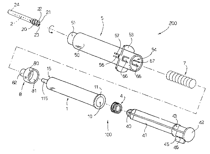
Figure 1 is an exploded axonometric view, illustrating the guard mechanism
according to
the invention and a conventional syringe;
Figure 2 is an axial sectional view of a sleeve forming part of the guard
mechanism of
Figure 1;
Figure 3 is an axial sectional view of a spring abutment member forming part
of the
guard mechanism of Figure l;
Figure 4 is a view, partially in axial section, of the syringe of Figure 1
assembled with
the guard mechanism, wherein the shaft of the plunger has not been sectioned
and has a
safety tab and the needle is shown partially broken off;
Figure 5 is an axial sectional view, like Figure 4, of the syringe assembled
with the guard
mechanism, wherein the safety tab of the plunger shaft has been removed and
the plunger
is at its forward end-of stroke point;
Figure 6 is an axial sectional view, like Figure 4, of the syringe assembled
with the guard
mechanism, wherein the needle is in the safety position protected by the
sleeve and
wherein the syringe body and plunger shaft assembly is shown partially broken
off;
Figure 7 is an axonometric view of the syringe assembled with the guard
mechanism,
during use; and
Figure 8 is an axonometric view of the syringe assembled with the guard
mechanism in
the safety position.
The guard mechanism according to the invention, attachable to a syringe to
make it into a
disposable automatic safety syringe, is described with the aid of the figures.
CA 02506465 2005-05-17
WO 2004/045685 - 5 - PCT/IT2002/000730
With reference for now in particular to Figure 1, there is illustrated a
conventional
syringe, denoted as a whole with reference numeral 100, and guard mechanism
consisting of a set of components, denoted as a whole by reference numeral
200.
The syringe 100 is a syringe commonly available on the market and comprises a
syringe
body 1, an injection needle 2, a plunger 4 and a shaft 41.
The syringe body 1 is cylindrical, hollow on the inside, and defines a
cylindrical chamber
10. The rear end of the body 1 is outwardly open and has an annular collar 11
that
protrudes radially outward. Two tongues or flanges (not shown) that protrude
radially
outward, in diametrically opposite positions, can be provided on the annular
rim 11 to
define gripping means for the user's fingers.
The front end of the body 1 ends in a head 115, outwardly open, having the
shape of a
substantially cylindrical or frusto-conical tang, with a much smaller diameter
than the
body l, so as to define a shoulder 15 on the front part of the syringe body 1.
The inj ection needle 2 is mounted on or built-in in a cylindrical or frusto-
conical needle-
carner 20, hollow on the inside, having an axial chamber 23 able to receive
the tang 115
of the head of the syringe body. The needle-carrier 20 can have, at its free
end, a collar
21 with two tongues 22 protruding radially in diametrically opposite
positions. The
tongues 22 can be replaced by an outer thread. A needle cap 24 engages with
the needle-
carrier 20 to cover the needle 2.
The plunger 4 can slide sealingly inside the chamber 10 of the syringe body 1.
The
plunger 4 is mounted on the head 40 of the shaft 41. The shaft 41 is cross-
shaped in cross
section and ends at the rear in a disc-shaped flange 42 which provides an
abutment
surface for the user's fingers during the inj ection.
Near the rear flange 42, around the shaft 41, an operating crown or disc 43
can be
provided. A safety tongue 45 that protrudes radially and longitudinally
outward from the
shaft 41 is disposed between the rear flange 42 and the operating crown 43.
The safety
tab 45 is connected to the shaft 41 by means of a brealcable connecting strip
46, such as a
strip of perforated material acting as a line of weakening. In this manner the
user can
remove the safety tongue 45 manually by tearing the line of weakening 46.
CA 02506465 2005-05-17
WO 2004/045685 - 6 - PCT/IT2002/000730
The operating crown 43 can be made in a single body with the shaft 41 or with
the rear
flange 42 of the shaft 41. In the case of the shaft 41 of the conventional
syringe 100 not
having the operating crown 43, said operating crown 43 can be made as a
separate
element forming part of the set of components 200 and thus able to be
assembled to the
shaft 41, as shown in the figures.
The set of components 200 comprises a sleeve 5, a spring 7, an abutment member
8 for
the spring and optionally an operating crown 43.
As shown also in Figure 3, the abutment member 8 has a cylindrical or frusto-
conical
body 80 hollow on the inside, having an axial cavity 81 with a diameter
substantially
equal to the outside diameter of the front part of the syringe body 1 to be
able to attached
thereto by pressure. The abutment member 8 has at the front and axially a
cylindrical or
frusto-conical tang 82, with a smaller diameter than that of the body 80, so
as to give rise
to a shoulder 84. The tang 82 is hollow on the inside and has an inside thread
83.
In this manner, when the abutment member 8 is applied to the head of the
syringe body,
the tang 115 of the syringe body is disposed axially inside the tang 82 of the
abutment
member, leaving an annular space between the outer surface of the tang 115 of
the
syringe body and the inner surface of the tang 82 of the needle-carrier
member, so as to
give rise to a so-called Luer cone on the head of the syringe body to receive
the needle-
carrier 20 of the injection needle 2. In this case, the abutment member 8 acts
as a
supporting member for the needle 2.
As shown also in Figure 2, according to the invention, the set of components
200
comprises a safety device for the syringe, denoted by reference numeral 5 and
taking the
form of a substantially cylindrical sleeve, hollow on the inside, having an
axial chamber
open at the front and rear. The sleeve 5 has a front part 51 with a smaller
diameter ending
in an annular collar 52 that protrudes radially inward. The inside diameter of
the body 50
of the sleeve body is slightly greater than the outside diameter of the body
80 of the
abutment member 8, so that the sleeve 5 can slide axially on the body 80 of
the abutment
member 8, when the abutment member 8 is applied to the head of the syringe
body 1.
Near the rear part of the body 50 of the sleeve there are provided two rigid
tongues or
flanges 53 which protrude radially outward, in diametrically opposite
directions, to give
rise to a resting surface for the user's fingers.
CA 02506465 2005-05-17
WO 2004/045685 - 7 - PCT/IT2002/000730
Two pairs of longitudinal flexible tongues 56, 66 are provided in the rear
part of the body
50 of the sleeve, forward and rearward with respect to the flanges 53,
respectively.
The first pair of tongues 56 is disposed forward of the flanges 53 and has two
tongues 56
disposed in diametrically opposite positions. Each front tongue 56 is slightly
inclined
towards the inside and ends in a rear abutment surface 58. Each front tongue
56 is
defined by a substantially U-shaped cut 57 made on the body of the sleeve, so
as to be
able to bend with respect to the sleeve body.
The second pair of tongues 66 is disposed to the rear of the flanges 53 and
has two
tongues 66 disposed in diametrically opposite positions. Each rear tongue 66
is inclined
slightly inward and ends in a front abutment surface 68, substantially opposed
to the rear
abutment surface 58 of the respective front tongue 56. Each rear tongue 66 is
defined by
a substantially U-shaped cut 67 made in the body of the sleeve, so as to be
able to bend
with respect to the body of the sleeve.
Lastly, the set of components 200 comprises the spiral spring 7, designed to
be housed in
the front part 52 of the sleeve body. In fact the outside diameter of the
spring 7 is slightly
smaller than the inside diameter of the front part 51 of the sleeve body S.
Assembly of the set of components 200 on the syringe 100 will be described
hereunder,
purely by way of example, with the aid also of Figure 4.
The guard mechanism 200 can be supplied pre-assembled. That is to say, the
spring 7 is
inserted in the sleeve 5, from the rear of the sleeve 5, so that the end of
the spring abuts
against the collar 52 of the front part of the sleeve 5. The abutment member 8
for the
spring is then inserted into the sleeve, again from the rear of the sleeve, so
that the
shoulder 84 of the abutment member abuts against the other end of the spring.
Then, by
lightly forcing the abutment member 8 into the sleeve, the body 80 of the
abutment
member passes the pair of rear tongues 66 and thus the rear edge of the
abutment
member is blocked by the front abutment surface 68 of the rear tongues of the
sleeve,
preventing the abutment member from coming out of the sleeve.
At this point the pre-assembled protection mechanism 200 can be attached to a
conventional syringe 100, mechanically or manually. In fact, it is sufficient
to force the
CA 02506465 2005-05-17
WO 2004/045685 - 8 - PCT/IT2002/000730
syringe body 1 into the sleeve 5, from the rear of the sleeve. In this manner
the tang 115
of the syringe body is inserted into the abutment member 8 until the shoulder
15 of the
syringe body 1 abuts against the shoulder 84 of the abutment member. In this
situation
the abutment member 8 is integral with the front part of the syringe body 1
and a Luer
cone consisting of the inside tang 115 of the syringe body and the outside
tang 82 of the
abutment member is formed in the head of the syringe body. By advancing the
syringe
body and causing the tongues 56 to bend slightly outwards, possibly with the
aid of
suitable means, the syringe body pushes the abutment member 8 slightly
forward,
compressing the spring in the front part 51 of the sleeve.
As shown in Figure 4, when the rear edge 11 of the syringe body passes the
pair of rear
tongues 66 of the sleeve, the front abutment surface 68 of the rear tongues 66
abuts
against the rear edge 11 of the syringe body, preventing the syringe body from
coming
out of the sleeve 5 through the action of the spring 7. At this point the
syringe 100 with
the guard mechanism 200 is ready for use.
It should be noted that in this situation the safety tab 45 fixed to the shaft
41 abuts against
the rear edge of the sleeve 5, preventing the shaft 41 from advancing further,
so that the
operating crown 43 does not cooperate with the rear tongues 66 of the sleeve,
triggering
the guard mechanism 200.
Operation of the syringe 100 provided with the guard mechanism 200 according
to the
invention is described hereunder with reference to Figures 5 to 8.
Before carrying out the injection, the user manually tears the safety tab 45
along the
perforated line of weakening 46.
As shown in Figure 5, when the plunger 4 reaches the end of its injection
stroke inside
the chamber of the syringe body, the operating crown 43 of the shaft 41 comes
into
contact with the flexible rear tongues 66 of the sleeve, causing outward
bending of said
tongues 66.
As a result, the rear edge 11 of the syringe body disengages from the
protrusions 68 of
the rear tongues 66. Consequently, axial movement of the sleeve 5 with respect
to the
syringe body 1 is no longer prevented. Thus through the action of the spring 7
which is
released, the sleeve 5 can move axially forward with respect to the syringe
body 1 and/or
CA 02506465 2005-05-17
WO 2004/045685 - 9 - PCT/IT2002/000730
the syringe body 1 can move axially rearward with respect to the sleeve 5. It
should be
noted movement of the sleeve 5 takes place automatically through the action of
the
spring 7 without the need for any manual intervention by the user.
As shown in Figure 7, said telescopic movement of the sleeve 5 and of the
syringe 100 is
controlled and regulated by the user's hand. In fact the user keeps the index
and middle
finger on the flanges 53 of the sleeve and the thumb on the rear flange 42 of
the plunger
shaft, accompanying the stroke of the sleeve 5 and of the syringe 100 towards
the
position of safety and thus regulating the speed of relative movement of the
sleeve 5 with
respect to the syringe 1 as desired by the user.
At the end of the stroke of the sleeve 5, as shown in Figures 6 and 8, the
body 80 of the
abutment member 8 is retained between the two pairs of tongues 56 and 66. That
is to
say, the rear abutment surface 58 of the front tongues 56 abuts against the
shoulder 84 of
the abutment member, preventing forward movement thereof, whilst the front
abutment
surface 68 of the rear tongues 66 abuts against the rear edge of the body 80
of the
abutment member, preventing rearward movement thereof. Detachment of the
abutment
member 8 from the syringe body can be caused by exerting a strong forward
traction on
the sleeve, but the needle 2 nevertheless remains trapped, together with the
abutment
member, in the sleeve 5.
It should be noted that in the present invention, the spring 7 remains
protected inside the
sleeve 5, even when the sleeve 5 is in its forward safety position.
It should further be noted that in the present invention, a syringe of a
conventional type,
composed of the body 1, the plunger 4 with the shaft 41 thereof and the needle
2 with
the support 20 thereof, is made into a safety syringe by the use of only three
additional
elements forming part of the guard mechanism 200, that is to say, the sleeve
5, the spring
7 and the abutment member 8. Furthermore, the set of components 200 can
optionally
also comprise the operating crown 43 to be applied to the shaft 41 of the
piston, in the
event of said operating crown 43 not being made integral or in a single body
with the
shaft 41.
Numerous variations or modifications of detail within the reach of a person
skilled in the
art can be made to the present embodiment of the invention, without thereby
departing
from the scope of the invention as set forth in the appended claims.