Sélection de la langue

Search

Sommaire du brevet 2506652 

Énoncé de désistement de responsabilité concernant l'information provenant de tiers

Une partie des informations de ce site Web a été fournie par des sources externes. Le gouvernement du Canada n'assume aucune responsabilité concernant la précision, l'actualité ou la fiabilité des informations fournies par les sources externes. Les utilisateurs qui désirent employer cette information devraient consulter directement la source des informations. Le contenu fourni par les sources externes n'est pas assujetti aux exigences sur les langues officielles, la protection des renseignements personnels et l'accessibilité.

Disponibilité de l'Abrégé et des Revendications

L'apparition de différences dans le texte et l'image des Revendications et de l'Abrégé dépend du moment auquel le document est publié. Les textes des Revendications et de l'Abrégé sont affichés :

  • lorsque la demande peut être examinée par le public;
  • lorsque le brevet est émis (délivrance).
(12) Brevet: (11) CA 2506652
(54) Titre français: ORNEMENT DE PELOUSE SOUTENANT UN INSTRUMENT METEOROLOGIQUE
(54) Titre anglais: A DECORATIVE LAWN ORNAMENT FOR SUPPORTING A WEATHER DEVICE
Statut: Périmé et au-delà du délai pour l’annulation
Données bibliographiques
Abrégés

Abrégé français

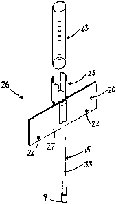
Il s'agit d'une décoration de pelouse destinée à soutenir un objet tel qu'un pluviomètre comprenant une partie décorative, un dispositif de soutien et un mécanisme de soutien. L'élément décoratif est composé d'une plaque métallique de forme attrayante munie d'une cavité pour pouvoir la monter sur le dispositif de soutien. Le dispositif de soutien présente une partie réceptrice pour soutenir l'objet, une partie d'assemblage dans laquelle insérer la plaque amovible et une partie de renfort pour soutenir la partie dite réceptrice sur la partie dite d'assemblage. La partie d'assemblage est munie d'une rainure sur le dessus d'un élément en saillie s'étendant d'un côté à l'autre de la plaque à travers la cavité. Pour monter la plaque sur le dispositif de soutien, le bord supérieur de la cavité de la plaque s'ajuste à l'intérieur de la rainure et le bord inférieur de la cavité glisse par dessus la surface inférieure de l'élément en saillie et la plaque se trouve enclenchée à sa place. Le mécanisme de soutien comprend une tige amovible engagée dans un trou au bas de l'élément en saillie, de telle sorte que la tige peut être enfoncée dans le sol pour soutenir l'ensemble.


Abrégé anglais

A decorative lawn ornament for supporting an object, such as a rain gauge, comprises an assembly featuring a decorative member, a support device and a support mechanism. The decorative member comprises a metal plate shaped to have visual appeal having a hole therein for mounting on the support device. The support device features a receiving portion for supporting the object, a mounting portion for detachably engaging the plate and a reinforcing portion for supporting said receiving portion on said mounting portion. The mounting portion features a groove in the top surface of a protruding member which extends from one side of the plate to the other through the hole. To mount the plate on the support device, the top edge of the hole in the plate fits within the groove and the bottom edge of the hole slides over the bottom surface of the protruding member and snaps into place. The support mechanism comprises a rod removably engaged to a hole in the bottom of the protruding member, such that the rod can be driven into the ground to support the assembly.

Revendications

Note : Les revendications sont présentées dans la langue officielle dans laquelle elles ont été soumises.


-10-
CLAIMS:
1. A decorative assembly for supporting an object comprising:
a decorative member comprising a metal plate having a hole therein,
said hole having upper and lower edges;
a moulded plastic support device for supporting the object and the
decorative member, the support device comprising:
a receiving portion on a first side of the metal plate comprising:
a receptacle for supporting the object; and
walls extending upward from the receptacle to receive
and position the object;
and
a mounting portion comprising:
a main member extending downward from the receptacle
of the receiving portion on the first side of the plate;
a protruding member having an upper surface and a
lower surface, said protruding member extending from the main member through
the
hole in the plate to a second side of the plate opposite the first side;
a groove in the upper surface of the protruding member
for receiving and positioning the upper edge of the hole through the metal
plate; and
a hole in the lower surface of the protruding member;
and
a support rod for removably engaging the hole in the protruding
member of the support device and supporting said device thereon;

-11-
arranged such that the upper and lower edges of the hole in the metal
plate are removably engaged with the groove and lower surface respectively of
the
mounting portion of the support device.
2. The assembly according to Claim 1 wherein the support device
further comprises a reinforcing portion for supporting the receiving portion
on the
mounting portion.
3. The assembly according to Claim 2 wherein the reinforcing
portion comprises a support member supported centrally on the main member of
the
mounting portion, extending perpendicular thereto and spanning the height
thereof
such that said support member extends across the receptacle, thereby
supporting
the receiving portion.
4. The assembly of Claims 1 to 3 wherein each wall of the
receiving portion is curved such that a cylindrical object can be received and
positioned by said walls.
5. The assembly according to Claims 1 to 4 wherein an upper end
of the support rod and the hole in the mounting portion are threaded such that
they
can be detachably engaged.
6. The assembly according to Claims 1 to 5 wherein the support
rod comprises a mounting mechanism supported on a lower end of the support
rod.
7. The assembly according to Claim 6 wherein there is provided a
base member having a mounting member extending upward for engagement to the
mounting mechanism.
8. The assembly according to Claim 7 wherein the mounting

-12-
member comprises a threaded member.
9. The assembly according to Claims 6 to 8 wherein the mounting
mechanism comprises a threaded cylinder.
10. The assembly according to Claim 9 wherein the lower end of the
support rod is threaded such that the threaded cylinder can be detachably
engaged
to said support road.
11. The assembly according to Claims 1 to 10 wherein the
decorative member comprises mounting means for supporting the assembly on a
vertical surface.
12. The assembly according to Claim 11 wherein the mounting
means comprise at least one mounting hole through the plate such that a
fastener
can be passed through said mounting hole to the vertical surface.

Description

Note : Les descriptions sont présentées dans la langue officielle dans laquelle elles ont été soumises.


CA 02506652 2010-05-04
A DECORATIVE LAWN ORNAMENT FOR SUPPORTING
A WEATHER DEVICE
The present invention relates to a decorative lawn ornament for
supporting an object, such as a rain gauge.
BACKGROUND
In lawn and garden care, both decorative ornaments and weather
devices, such as rain gauges, are often used. Efforts have been made to
combine
the functional and decorative nature of these two classes of objects.
Decorative rain
gauges which often feature nature-oriented statuettes are an example of such a
combination. The resulting products, while both useful and visually appealing,
lack
adaptability and versatility as their method of display is limited to resting
on a
horizontal surface and their appearance is limited by the permanency of their
decorative aspect.
SUMMARY
According to one aspect of the present invention there is provided a
decorative assembly for supporting an object comprising:
a decorative member comprising a metal plate having a hole therein,
said hole having upper and lower edges;
a moulded plastic support device for supporting the object and the
decorative member, the support device comprising:
a receiving portion on a first side of the metal plate comprising:
a receptacle for supporting the object; and

CA 02506652 2010-05-04
-2-
walls extending upward from the receptacle to receive and
position the object;
and
a mounting portion comprising:
a main member extending downward from the receptacle of the
receiving portion on the first side of the plate;
a protruding member having an upper surface and a lower
surface, said protruding member extending from the main member through the
hole
in the plate to a second side of the plate opposite the first side;
a groove in the upper surface of the protruding member for
receiving and positioning the upper edge of the hole through the metal plate;
and
a hole in the lower surface of the protruding member;
and
a support rod for removably engaging the hole in the protruding
member of the support device and supporting said device thereon;
arranged such that the upper and lower edges of the hole in the metal
plate are removably engaged with the groove and lower surface respectively of
the
mounting portion of the support device.
Preferably the support device further comprises a reinforcing portion
for supporting the receiving portion on the mounting portion.
Preferably the reinforcing portion comprises a support member
supported centrally on the main member of the mounting portion, extending
perpendicular thereto and spanning the height thereof such that said support

CA 02506652 2010-05-04
-3-
member extends across the receptacle, thereby supporting the receiving
portion.
Preferably each wall of the receiving portion is curved such that a
cylindrical object can be received and positioned by said walls.
Preferably an upper end of the support rod and the hole in the
mounting portion are threaded such that they can be detachably engaged.
Preferably the support rod comprises a mounting mechanism
supported on a lower end of the support rod.
There may be provided a base member having a mounting member
extending upward for engagement to the mounting mechanism.
In this instance, preferably the mounting member comprises a
threaded member.
Preferably the mounting mechanism comprises a threaded cylinder.
Preferably the lower end of the support rod is threaded such that the
threaded cylinder can be detachably engaged to said support road.
Preferably the decorative member comprises mounting means for
supporting the assembly on a vertical surface.
Preferably the mounting means comprise at least one mounting hole
through the plate such that a fastener can be passed through said mounting
hole to
the vertical surface.
The present invention provides different ways to support the decorative
assembly depending on the desired location. In a first embodiment a support
rod
connected to the support device be driven into the ground or the decorative
member
can be fastened to a vertical surface with nails or screws installed through
holes

CA 02506652 2010-05-04
-4-
included for such a purpose. In the latter case, the support rod can be
removed
from the support device and stored for future use. In a second embodiment, a
base
member is provided for supporting the assembly by the support rod above the
ground on any horizontal surface.
The detachable engagement of the decorative member and the
support device makes it easy to change the appearance of the decorative
assembly.
A variety of decorative members, each featuring the same hole for engagement
with
the support device, would be interchangeable. In addition, should a situation
arise
where either the decorative or functional aspect of the device is no longer
desired,
the respective component of the assembly can be removed. For example, in a
decorative assembly for supporting a rain gauge, removal of the decorative
member
results in a purely functional rain gauge. In the same assembly, removal of
the rain
gauge results in a purely decorative yard ornament.
BRIEF DESCRIPTION OF THE DRAWINGS
In the accompanying drawings, which illustrate exemplary
embodiments of the present invention:
Figure 1 is an isometric view of a first embodiment of the present
invention shown in an assembled state for supporting a rain gauge.
Figure 2 is an isometric view of the first embodiment of the present
invention shown in an unassembled state.
Figure 3 is a side view of the support device of the present invention.
Figure 4 is a front view of the support device of the present invention.
Figure 5 is a top view of the support device of the present invention.

CA 02506652 2010-05-04
-5-
Figure 6 is a bottom view of the support device of the present
invention.
Figure 7 is an isometric view of a second embodiment of the present
invention in which a base member is provided for supporting the other
components.
DETAILED DESCRIPTION
The present invention, shown assembled and generally indicated by 26
in Figure 1, is intended for decoratively supporting an object, such as a rain
gauge
23, in a lawn or garden. The decorative assembly, shown unassembled in Figure
2,
is made up of three main components. A support device 25 and decorative member
20 are detachably connected to one another and supported on a support
mechanism
15.
The decorative member 20 comprises a metal plate 27 having a hole
21 therein for engagement with the support device 25. Mounting holes 22 are
included in order to add the option of hanging the decorative member 20 on a
vertical surface by means of appropriate fasteners, such as screws or nails.
While
shown as a rectangular plate in the drawings, the purpose of the decorative
member
is to add visual appeal to the rain gauge support, and therefore is cut,
painted,
coated or otherwise processed to form an ornamental piece. Laser cutting can
be
used to create the rectangular hole 21 and circular holes 22 as well as cut
the
20 decorative member 20 into an attractive shape. For example, the plate can
be cut to
form a silhouette of a nature scene, painted to add colour and then
protectively
coated for the prevention of wear by the elements.

CA 02506652 2010-05-04
-6-
The support device 25, illustrated without the other components in
Figures 3 to 6, is the most important component of the assembly 26, as it
detachably
supports both the rain gauge 23 and the decorative member 20. The support
device
comprises a receiving section 1, a mounting portion 2 and a reinforcing
portion 3.
The receiving portion 1 is intended for receiving and supporting the
rain gauge 23. A receptacle 6 is provided for the rain gauge 23 to rest on. On
either
side of the receptacle 6, near or at the edge, is an upward extending wall 4.
The
walls 4 are curved In order to receive and position the cylindrical rain gauge
23
between them.
The mounting portion 2 of the support device 25 features a main
member 12 extending vertically downward from the receptacle 6 of the receiving
portion 1 and a protruding member 9 spanning the height of the of the main
member
12. The protruding member 9 has a lower surface 13 and an upper surface 14. A
groove 10 of rectangular cross section in the upper surface 14 extends across
the
protruding member 9 along the width of the main member 12. The groove 10 is of
such a width that the thickness of the decorative member 20 will fit therein.
The
portion of the upper surface 14 of the protruding member 9 on the side of the
groove
10 opposite the main member 12 is flat and generally semicircular in shape.
The
combination of this semicircular portion of the upper surface 14 and rectangle
formed by the length and width of the groove 10 constitutes the cross
sectional
shape of the protruding member 9. The upper surface 14 of the vertical member
9
lies in a horizontal plane while the lower surface 13 is inclined upward from
the
bottom of the main member 12, as best seen in the side view shown in Figure 3.

CA 02506652 2010-05-04
-7-
The slope of the inclined lower surface 13 corresponds to the fact that the
vertical
distance from the upper surface 14 to the lower surface 13 along the side of
the
protruding member 9 opposite the main member 12 is the same as the vertical
distance from the bottom of the rectangular groove 10 to the lower surface 13
along
the main member 12. This distance corresponds to the height of the rectangular
hole 21 in the decorative member 20 shown in Figure 2. This arrangement
creates a
way to detachably mount the decorative member 20 on the mounting portion 2 of
the
support device 25. The upper edge 28 of the hole 21 in the decorative member
20 is
placed within the rectangular groove 10 in the upper surface 14 of the
protruding
member 9. The lower edge 29 of the hole 21 is then pulled toward the main
member
12 of the mounting portion 2 over the lower surface 13 of the protruding
member 9.
Since the height of the protruding member 9 along the main member 12
corresponds
to the height of the hole 21, the decorative member 20 snaps into place
against said
main member 12. The decorative member 20 and support device 25 can be seen in
their assembled state in Figure 1.
In addition to providing a way to attach the decorative member and
support device to each other, the mounting portion 2 also provides a means of
supporting the entire decorative assembly 26 on the support mechanism 15. A
hole
11 in the bottom surface 13 of the protruding member 9 is threaded to engage a
corresponding threaded upper end 18 of a support rod 33. A threaded cylinder
19 is
attached to the rod 33 by means of a threaded lower end similar to threaded
upper
end 18. The decorative assembly can be removably installed in a yard or garden
by
driving the support rod 33 into the ground, with or without the threaded
cylinder 19

CA 02506652 2010-05-04
-8-
attached, such that the earth surrounding the rod will prevent the assembly 26
from
tipping over. The invention can be easily moved to a new location by
withdrawing
the rod 33 from the ground and moving the assembly 26 to any area where ground
conditions will allow reinsertion of the rod. The support device 25 and
decorative
member 20 can also be installed without the support rod 33 by using suitable
fasteners to engage the decorative member 20 to a vertical surface through the
mounting holes 22. When installed, the support rod also acts as a locking
mechanism that helps ensure that the decorative member 20 remains snapped in
place on the mounting portion 2 of the support device 25, as the decorative
member
is housed between the rod 33 and the main member 12 of the mounting portion.
The reinforcing portion 3 of the supporting device is included to help
support the receiving portion 1 on the mounting portion 2. A support member 32
comprises an upper segment 7 and a lower segment 8. The support member 32
extends centrally from the main member 12 of the mounting portion at a right
angle
and attaches to the lower surface of the receptacle 6, thereby helping support
the
receiving portion 1 on said mounting portion 2. Each of segments 7 and 8 is
curved
on the side opposite the main member 12.
A second embodiment of the invention, illustrated in Figure 7, provides
added flexibility by providing a means of supporting the decorative assembly
26 in
cases where the support rod 33 cannot be driven into the ground and the
decorative
member 20 cannot be fastened to a vertical surface. A base member 30 is
provided
for placement on a horizontal surface. A threaded vertical post 31 is
centrally
attached to the base member 30 and extends upward therefrom for engagement

CA 02506652 2010-05-04
-9-
with the threaded cylinder 19 on the rod 33. With the base member 30 and
support
mechanism 15 attached, the decorative assembly 26 is supported entirely above
the
ground. Positioning of this embodiment of the present invention is not
restricted by
the requirements of soft ground or a vertical surface, allowing the assembly
26 to be
installed in a wider variety of locations.
The versatility of the present invention is illustrated by its ability to
serve a purely functional purpose by supporting only the rain gauge 23, to
serve a
purely ornamental purpose by supporting only the decorative member 20 or to
serve
both purposes by simultaneously supporting the gauge 23 and the decorative
member 20. The invention is also adaptable to its environment as illustrated
by its
ability to be supported on a vertical surface, in the ground or on any hard
horizontal
surface.
While the embodiments described have been arranged for supporting
a cylindrical rain gauge, the invention can be easily modified to support
different
weather devices or other objects. Such modifications are well known to those
of skill
in the art.
Since various modifications can be made in my invention as herein
above described, and many apparently widely different embodiments of same made
within the spirit and scope of the claims without department from such spirit
and
scope, it is intended that all matter contained in the accompanying
specification shall
be interpreted as illustrative only and not in a limiting sense.

Dessin représentatif
Une figure unique qui représente un dessin illustrant l'invention.
États administratifs

2024-08-01 : Dans le cadre de la transition vers les Brevets de nouvelle génération (BNG), la base de données sur les brevets canadiens (BDBC) contient désormais un Historique d'événement plus détaillé, qui reproduit le Journal des événements de notre nouvelle solution interne.

Veuillez noter que les événements débutant par « Inactive : » se réfèrent à des événements qui ne sont plus utilisés dans notre nouvelle solution interne.

Pour une meilleure compréhension de l'état de la demande ou brevet qui figure sur cette page, la rubrique Mise en garde , et les descriptions de Brevet , Historique d'événement , Taxes périodiques et Historique des paiements devraient être consultées.

Historique d'événement

Description Date
Le délai pour l'annulation est expiré 2022-03-01
Lettre envoyée 2021-05-06
Lettre envoyée 2021-03-01
Lettre envoyée 2020-08-31
Inactive : COVID 19 - Délai prolongé 2020-08-19
Inactive : COVID 19 - Délai prolongé 2020-08-06
Inactive : COVID 19 - Délai prolongé 2020-07-16
Inactive : COVID 19 - Délai prolongé 2020-07-02
Inactive : COVID 19 - Délai prolongé 2020-06-10
Inactive : COVID 19 - Délai prolongé 2020-05-28
Inactive : COVID 19 - Délai prolongé 2020-05-14
Inactive : COVID 19 - Délai prolongé 2020-04-28
Représentant commun nommé 2019-10-30
Inactive : TME en retard traitée 2017-05-16
Lettre envoyée 2017-05-08
Inactive : Regroupement d'agents 2012-03-07
Accordé par délivrance 2010-09-28
Inactive : Page couverture publiée 2010-09-27
Préoctroi 2010-07-16
Inactive : Taxe finale reçue 2010-07-16
Lettre envoyée 2010-07-06
Un avis d'acceptation est envoyé 2010-07-06
Inactive : Approuvée aux fins d'acceptation (AFA) 2010-06-10
Lettre envoyée 2010-05-13
Requête d'examen reçue 2010-05-04
Exigences pour une requête d'examen - jugée conforme 2010-05-04
Toutes les exigences pour l'examen - jugée conforme 2010-05-04
Modification reçue - modification volontaire 2010-05-04
Lettre envoyée 2009-06-08
Exigences de rétablissement - réputé conforme pour tous les motifs d'abandon 2009-05-25
Réputée abandonnée - omission de répondre à un avis sur les taxes pour le maintien en état 2009-05-06
Déclaration du statut de petite entité jugée conforme 2007-09-19
Demande publiée (accessible au public) 2006-11-06
Inactive : Page couverture publiée 2006-11-05
Lettre envoyée 2006-05-09
Inactive : Transfert individuel 2006-04-13
Inactive : CIB attribuée 2005-10-19
Inactive : CIB en 1re position 2005-10-19
Inactive : Certificat de dépôt - Sans RE (Anglais) 2005-06-14
Inactive : Lettre de courtoisie - Preuve 2005-06-14
Demande reçue - nationale ordinaire 2005-06-14

Historique d'abandonnement

Date d'abandonnement Raison Date de rétablissement
2009-05-06

Taxes périodiques

Le dernier paiement a été reçu le 2010-03-02

Avis : Si le paiement en totalité n'a pas été reçu au plus tard à la date indiquée, une taxe supplémentaire peut être imposée, soit une des taxes suivantes :

  • taxe de rétablissement ;
  • taxe pour paiement en souffrance ; ou
  • taxe additionnelle pour le renversement d'une péremption réputée.

Les taxes sur les brevets sont ajustées au 1er janvier de chaque année. Les montants ci-dessus sont les montants actuels s'ils sont reçus au plus tard le 31 décembre de l'année en cours.
Veuillez vous référer à la page web des taxes sur les brevets de l'OPIC pour voir tous les montants actuels des taxes.

Historique des taxes

Type de taxes Anniversaire Échéance Date payée
Taxe pour le dépôt - petite 2005-05-06
Enregistrement d'un document 2006-04-13
TM (demande, 2e anniv.) - petite 02 2007-05-07 2007-04-23
TM (demande, 3e anniv.) - petite 03 2008-05-06 2008-03-25
TM (demande, 4e anniv.) - petite 04 2009-05-06 2009-05-25
Rétablissement 2009-05-25
TM (demande, 5e anniv.) - petite 05 2010-05-06 2010-03-02
Requête d'examen - petite 2010-05-04
Taxe finale - petite 2010-07-16
TM (brevet, 6e anniv.) - petite 2011-05-06 2011-02-23
TM (brevet, 7e anniv.) - petite 2012-05-07 2012-05-02
TM (brevet, 8e anniv.) - petite 2013-05-06 2013-05-01
TM (brevet, 9e anniv.) - petite 2014-05-06 2014-03-04
TM (brevet, 10e anniv.) - petite 2015-05-06 2015-05-04
TM (brevet, 11e anniv.) - petite 2016-05-06 2016-05-03
TM (brevet, 12e anniv.) - petite 2017-05-08 2017-05-16
Annulation de la péremption réputée 2017-05-08 2017-05-16
TM (brevet, 13e anniv.) - petite 2018-05-07 2018-03-01
TM (brevet, 14e anniv.) - petite 2019-05-06 2019-04-11
Titulaires au dossier

Les titulaires actuels et antérieures au dossier sont affichés en ordre alphabétique.

Titulaires actuels au dossier
CRYSTAL SPRING COLONY FARMS LTD.
Titulaires antérieures au dossier
DAVID WALDNER
Les propriétaires antérieurs qui ne figurent pas dans la liste des « Propriétaires au dossier » apparaîtront dans d'autres documents au dossier.
Documents

Pour visionner les fichiers sélectionnés, entrer le code reCAPTCHA :


Pour visualiser une image, cliquer sur un lien dans la colonne description du document. Pour télécharger l'image (les images), cliquer l'une ou plusieurs cases à cocher dans la première colonne et ensuite cliquer sur le bouton "Télécharger sélection en format PDF (archive Zip)" ou le bouton "Télécharger sélection (en un fichier PDF fusionné)".

Liste des documents de brevet publiés et non publiés sur la BDBC .

Si vous avez des difficultés à accéder au contenu, veuillez communiquer avec le Centre de services à la clientèle au 1-866-997-1936, ou envoyer un courriel au Centre de service à la clientèle de l'OPIC.


Description du
Document 
Date
(aaaa-mm-jj) 
Nombre de pages   Taille de l'image (Ko) 
Description 2005-05-05 9 366
Abrégé 2005-05-05 1 29
Revendications 2005-05-05 3 87
Dessins 2005-05-05 5 87
Dessin représentatif 2006-10-15 1 4
Abrégé 2010-05-03 1 27
Description 2010-05-03 9 341
Revendications 2010-05-03 3 80
Certificat de dépôt (anglais) 2005-06-13 1 158
Courtoisie - Certificat d'enregistrement (document(s) connexe(s)) 2006-05-08 1 128
Rappel de taxe de maintien due 2007-01-08 1 111
Courtoisie - Lettre d'abandon (taxe de maintien en état) 2009-06-07 1 172
Avis de retablissement 2009-06-07 1 164
Rappel - requête d'examen 2010-01-06 1 125
Accusé de réception de la requête d'examen 2010-05-12 1 177
Avis du commissaire - Demande jugée acceptable 2010-07-05 1 164
Avis concernant la taxe de maintien 2017-05-15 1 178
Quittance d'un paiement en retard 2017-05-15 1 163
Avis du commissaire - Non-paiement de la taxe pour le maintien en état des droits conférés par un brevet 2020-10-18 1 549
Courtoisie - Brevet réputé périmé 2021-03-28 1 540
Avis du commissaire - Non-paiement de la taxe pour le maintien en état des droits conférés par un brevet 2021-06-16 1 558
Correspondance 2005-06-13 1 33
Correspondance 2005-06-13 1 25
Correspondance 2006-05-08 1 23
Correspondance 2007-01-08 1 40
Correspondance 2007-09-18 2 44
Correspondance 2009-06-07 1 88
Taxes 2009-05-24 2 84
Correspondance 2010-01-06 1 25
Correspondance 2010-05-12 1 72
Correspondance 2010-07-05 1 85
Correspondance 2010-07-15 2 57