Note : Les descriptions sont présentées dans la langue officielle dans laquelle elles ont été soumises.
CA 02509082 2005-06-02
1 "ROTARY PUMP STABILIZER"
2
3 FIELD OF THE INVENTION
4 The invention relates to a dynamic pressure-responsive apparatus
used for the stabilization of tools suspended from production tubing, said
tools
6 being subject to undesirable lateral movement, and particularly tools
subject to
7 vibration in operation such as progressive cavity pumps.
8
9 BACKGROUND OF THE INVENTION
Apparatus are known for stabilizing various well tools which are
11 suspended at the bottom of a production tubing string. An example of a tool
12 which would benefit from stabilization is a rotary or progressive cavity
pump ("PC
13 pump"). A PC pump is located within an oil well, positioned at the bottom
end of
14 a production tubing string which extends down the casing of the well. The
pump
pressurizes well fluids and drives them up the bore of the production tubing
16 string to the surface. The pump comprises a pump stator coupled to the
17 production tubing string, and a rotor which is both suspended and
rotationally
18 driven by a sucker rod string extending through the production tubing
string bore.
19 The stator is held from reactive rotation by a tool anchored against the
casing.
Usually this anti-rotation tool or torque anchor is located at the base of the
stator
21 and typically applies serrated slips to grip against the casing.
22 The rotor is a helical element which rotates within a corresponding
23 helical passage in the stator. Characteristically, the rotor does not
rotate
24 concentrically within the stator but instead scribes a circular or
elliptical path.
CA 02509082 2005-06-02
1 This causes vibration and oscillation of the sucker rod, the pump's stator
and the
2 tubing attached thereto.
3 The greater the pump flow, the greater is the vibration. This can
4 lead to loosening of the slips and functional failure of the no-turn tool.
Other
problems include fatigue failure of the connection of the stator to the tubing
or
6 nearby tubing-to-tubing connections.
7 In the prior art, bow springs have typically been used to centralize
8 and stabilize the stator and the supporting tubing. By design, the bow
springs
9 are radially flexible, in part to permit installation and removal through
casing.
Unfortunately, the spring's flexibility permits cyclic movement, resulting in
fatigue
11 and eventual failure of the springs.
12 Unitary tubing string centralizers generally position the tool in a
13 concentric or central position in the welt. While these centralizers may
provide a
14 positioning function, they are not effective as a tool-stabilizing means.
The
known centralizers are passive devices and do not actively contact the casing.
16 More sophisticated apparatus are known which more positively
17 secure and position tools within a well. For example, in U.S. Patent
2,490,350 to
18 Grable, a centralizer is provided using mechanical linkages which lock
radially
19 outwardly to engage the casing. Each of a plurality of two-bar linkages is
held
tight to the outside of the tubing string with a retaining bolt. A
longitudinal spring
21 and longitudinal ratchet are arranged external to the tubing for pre-
loading of one
22 link with the potential to jack-knife the linkage outwardly, except for the
23 restraining action of the retaining bolt. A radial plunger extends through
the
24 tubing wall to contact the linkage. The plunger has limited stroke. When
the
tubing string bore is pressurized, the plunger urges the linkage sufficiently
2
CA 02509082 2005-06-02
1 outwardly to break the retaining bolt, permitting the spring to drive the
linkage
2 radially outwardly. The driven link engages the ratchet, ensuring the
linkage
3 movement is uni-directional.
4 In U.S. Patent 4,960,173 to Cognevich, a tubular housing is also
disclosed having mechanical linkages which are held tight to the housing
during
6 installation. The linkages are irreversibly deployed upon melting of a
fusible link
7 at downhole conditions. An annular compression spring actuates a telescoping
8 sleeve which deploys a four-bar linkage and forcibly holds the linkage
against
9 the casing wall. Rollers on the ends of two of the linkages contact the
casing
wall for aiding in limited longitudinal movement of the tubular housing once
the
11 linkages are deployed. Gradual radial adjustment of the linkage is
permitted by
12 a fluid bleed to permit the telescoping sleeve to slowly retract during
this
13 movement. If the bleed fails and additional radial movement continues, a
pin will
14 shear, fully releasing the telescoping sleeve and linkage from the
compression
spring.
16 In summary, both Grable and Cognevitch disclose apparatus
17 which: rely upon compression spring force alone to drive and hold the
linkages
18 radially outwardly; do not deploy or extend the linkage until after
installation on
19 the casing; result in an irreversible deployment; and in the case of
Grable, do not
permit movement or removal without damage to the linkage, and in the case of
21 Cognevitch, limited movement is permitted but if the linkage cannot accept
the
22 movement required, a jarring action will shear a pin and irreversibly
separate the
23 compression spring from the linkage.
24 In Canadian Patent Application 2,296,867 to Tessier, a tubular
stabilizing apparatus is disclosed having a sliding dog disposed in a
longitudinal
3
CA 02509082 2005-06-02
1 pocket formed in the exterior of the tubular body. The sliding dog is
activated by
2 pistons pivotally connected to the sliding dog whereby fluid pressure within
the
3 piston bore dynamically drives the pistons to move the sliding dog along a
ramp
4 formed within the pocket. The tip of the sliding dog is thereby driven
upwardly
and outwardly to contact and brace against the casing, with the opposite side
of
6 the tubular body contacting the casing.
7 While the stabilizing apparatus of Tessier provides several
8 advantages over the prior art, under some circumstances, the two-point
contact
9 of the tip of the sliding dog and the opposing tubular body with the casing
may
not provide sufficient stabilization against movement transverse to the plane
of
11 contact.
12 There is, therefore, a need for an improved stabilizing apparatus.
4
CA 02509082 2005-06-02
1 SUMMARY OF THE INVENTION
2 A stabilizer is provided for securely and releasably stabilizing
3 downhole tools suspended from a production tubing string containing fluid
under
4 varying pressure. Such a tool is associated with or is the source of lateral
movement within the casing.
6 In a broad aspect of the invention, the stabilizer is positioned
7 between a well tool, such as a PC pump, and the production tubing string.
The
8 stabilizer comprises a tubular body having a cylindrical wall and a
longitudinal
9 bore contiguous with that of the production tubing string. A releasable
stabilizing
means or assembly is disposed on the exterior of the tubular body that extends
11 radialiy outward to contact the casing when actuated. At least two
12 circumferentially spaced-apart feet extend radially outward from the
tubular body
13 to contact the casing when the stabilizer is actuated. More particularly,
the angle
14 between the stabilizer and the feet adjacent to the stabilizing means is
greater
than ninety degrees, preferably in the range of about 110 degrees to about 160
16 degrees, and most preferably about 120 degrees, such that the feet bear
17 reactive force against the stabilizing means to substantially arrest
lateral
18 movement in any direction. Preferably, there are two feet equidistant from
the
19 stabilizing means and at an angle of about 120 degrees forming a three-
point
contact of the feet and the stabilizer with the casing.
21 In one embodiment, the stabilizer utilizes fluid pressure to actively
22 and forcefully stabilize the tool against lateral movement in any
direction.
23 Further, when the fluid pressure diminishes, such as when no fluid is being
24 produced, the apparatus may be readily repositioned, repeatedly installed
or
removed without irreversible alteration of the apparatus or peripheral damage.
5
CA 02509082 2005-06-02
1 The apparatus is dynamically responsive so as to provide greater stabilizing
2 force at higher fluid pressures, for instance, in the case of a PC pump
tool, when
3 the pump is pumping more vigorously.
4 Preferably, the stabilizing means comprises a radially outwardly
extendable sliding dog operably connected to a fluid pressure-driven actuating
6 means or actuator comprising one or more pistons, housed and moveable within
7 piston bores formed in a piston housing. The piston bore is in communication
8 with the bore of the tubular body so that it is pressurized dynamically with
fluid.
9 Fluid pressure causes the pistons to advance uphole, driving the sliding dog
upward to be driven up at feast one ramp, so as to move radially outwardly to
11 contact and brace against the casing, with the radial force being
proportional
12 with the fluid pressure. Preferably, there are two longitudinally spaced-
apart
13 ramps and the sliding dog and the pistons are connected by a pivotable fink
such
14 that the sliding dog is substantially parallel with the casing when
actuated.
The stabilizer can also include a shear pin extending thought the
16 wall of the tubular body and the stabilizing means to prevent pre-actuation
of the
17 stabilizer, such as when the stabilizer is being installed within the well.
Further,
18 stops can be provided that limit longitudinal movement of the stabilizing
means
19 or actuating means to obviate a possible jamming of the stabilizer in the
well.
6
CA 02509082 2005-06-02
1 BRIEF DESCRIPTION OF THE DRAWINGS
2 In drawings which are intended to illustrate embodiments of the
3 invention and which are not intended to limit the scope of the invention:
4 Figure 1 is a cross-sectional view of the lower end of a well casing
with the stator of a PC pump located therein, the pump having an embodiment of
6 the stabilizer of the present invention connected thereabove for stabilizing
the
7 pump and tubing within the casing, and with the cross-section of the
stabilizer
8 taken along line i-I of Fig. 3B;
9 Figure 2 is a partially exploded perspective view the stabilizer
according to Fig. 1;
11 Figure 3A and 3B are top end views of the stabilizer taken along
12 the lines III-III of Figs. 4A and 4B, respectively, with the stabilizer
installed in a
13 well casing and shown in the non-actuated condition (Fig 3A) and actuated
14 condition (Fig. 3B);
Figures 4A and 4B are elevational views of the stabilizer according
16 to Fig. 1, with part of the piston housing cut away and shown in the non-
actuated
17 condition (Fig. 4A) and actuated condition (Fig. 4B); and
18 Figures 5A and 5B are cross-sectional views taken along lines V-V
19 of Figs. 4A and 4B, respectively, with the stabilizer installed in a well
casing.
Figure 6 is a cross-sectional view of an alternative embodiment of
21 a stabilizer according to the present invention with the stabilizer
installed in a
22 well casing and in the actuated condition.
7
CA 02509082 2005-06-02
1 DETAILED DESCRIPTION OF THE PREFERRED EMBODIMENT
2 Having reference to Fig. 1, one embodiment of a stabilizer 2 is
3 located within the bore 3 of the casing 4 of a completed oil well 6. The
stabilizer
4 2 is suspended from a production tubing string 7 and connected to a downhole
well tool such as a rotary pump. Shown in this embodiment, the stabilizer 2 is
6 connected co-axially via a pup joint 8 to the stator 10 of a progressive
cavity
7 pump ("PC pump") 12 located within the well casing 4. The PC pump 12 is
8 therefore suspended from the production tubing string 7 by connection
through
9 the stabilizer 2. In operation, the PC pump 12 pressurizes well fluids and
directs
them up the bore 13 of the production tubing string 7 to the surface.
11 In the context of a PC pump 12, its stator 10 is secured against
12 reactive torque rotation in the casing 4. While not shown, it is understood
that
13 the stator 10 is secured using an anti-rotation tool or a torque anchor
usually
14 positioned at the lower end of the PC pump 12. The rotor of the PC pump 12,
which is not shown for clarity of the other components, would be typically
16 suspended and rotationally driven from a sucker rod, also not shown.
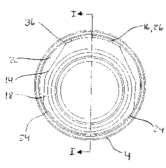
17 Referring also to Figs. 2, 3A and 3B, the stabilizer 2 comprises a
18 tubular body 14 and a releasable stabilizing means or assembly 16 disposed
on
19 the exterior 17 of the tubular body 14. The tubular body 14 has a
contiguous
annular wall 18 forming a longitudinal bore 20 extending therethrough for
21 passing pressurized well fluids pumped from the PC pump 12, through the
22 tubular body bore 20 and up the production tubing string bore 13 to the
surface.
23 An annular space 22 is formed between the tubular body 14 and the casing 4.
24 The releasable stabilizing means 16 is radially outwardly extendible
to engage the casing 4. Actuation such as by fluid pressure in the tubular
body
8
CA 02509082 2005-06-02
1 bore 20 (PB), which is greater than the pressure in the annulus 22 (PA),
forcibly
2 actuates and braces the stabilizing means 16 against the casing 4 and
thereby
3 jams the tubular body 14 against the opposing side of the well casing 4 to
4 substantially arrest oscillatory movement of the PC pump stator 10. The
stabilizing means 16 is dynamically actuated by fluid pressure which makes the
6 stabilizing capability stronger as the fluid pressure PB increases.
7 In greater detail, the tubular body 14 is profiled to provide at least
8 two longitudinally extending and circumferentially spaced-apart protrusions
or
9 feet 24. The effective diameter of the stabilizer 2 before actuation is less
than
the diameter of the casing bore 3 to permit installation of the stabilizer 2
therein.
11 The angle A between the stabilizing means 16 and each of the feet 24
adjacent
12 to the stabilizing means 16 is greater than 90 degrees, preferably in the
range of
13 about 110 degrees to about 160 degrees, such that when the stabilizing
means
14 16 is actuated, the stabilizing means 16 and the feet 24 contact the
casing. In
other words, each of the feet 24 need to bear opposing reactive force against
the
16 stabilizing means 16 when actuated. Preferably, there are two feet 24
17 equidistant from the stabilizing means 16 and the angle is about 120
degrees,
18 thereby forming a three point contact of the stabilizing means 16 and the
feet 24
19 with the casing 4 to substantially arrest lateral movement of the PC pump
10 in
any direction.
21 It is to be noted that while Fig. 3A shows the feet 24 contacting the
22 casing 4 in the non-actuated position, this is only to more clearly show
the radial
23 movement of the stabilizing means 16 within the annular space 22 upon
24 actuation. In fact, the stabilizer 2 is loosely and randomly fit within the
casing
bore 3 until it is actuated.
9
CA 02509082 2005-06-02
1 The stabilizing means 16 comprises a sliding dog 26 and a fluid
2 pressure-driven actuating means or actuator 28. Having further reference to
3 Figs. 4A, 4B, 5A and 5B, the sliding dog 26 is operable between a retracted
4 position (Figs. 4A, 5A) and a radially outwardly extended position (Figs.
4B, 5B)
for engagement of the sliding dog 26 with the casing 4.
6 The sliding dog 26 and actuating means 28 are positioned in a
7 longitudinally extending pocket 34 formed in a thickened portion 36 of the
8 annular wall 18. The pocket 34 extends radially inwardly or is recessed from
an
9 outer surface 38 of the tubular body 14. More particularly and as best seen
in
Fig. 2, the pocket 34 has an uphole portion 44 into which the sliding dog 26
is
11 disposed and a downhole portion 46 into which the actuating means 28 is
12 disposed. The sliding dog 26 and actuating means 28 are operatively
connected
13 by one or more links 48 positioned therebetween and pivotally attached
thereto
14 with pins 49, such as a roll pins. Each link 48 is a double link having
first and
second ends 48a, 48b to enable both axial and radial displacement of the
sliding
16 dog 26.
17 The uphole portion 44 includes a first, uphole ramp 50 and a
18 parallel second, downhole ramp 52 longitudinally spaced by a land 54 from
the
19 first ramp 50. The ramps 50, 52 extend longitudinally and outwardly from
the
floor 56 of the pocket 34. In operation, as shown in Figs. 4B and 5B, when the
21 tubular body bore 20 is pressurized for actuation (PB»PA), the actuating
means
22 28 is advanced longitudinally uphole for driving the sliding dog 26 against
the
23 first and second ramps 50, 52. The ramps 50, 52 deflect the sliding dog 26
24 radially outward, similar to the action of a parallelogram linkage, as the
links 48
pivot relative to the actuating means 28 and the sliding dog 26. Eventually,
as
CA 02509082 2005-06-02
1 the actuating means 28 advances, the sliding dog 26 radially contacts and
2 braces against the casing 4, with the sliding dog 26 being substantially
parallel to
3 the casing 4.
4 To prevent the sliding dog 26 from failing out of the pocket 34
during handling outside of the casing 4, while also subsequently permitting
6 movement of the sliding dog 26 as required, a shoulder screw 40 is affixed
to the
7 tubular body 14 and set within a longitudinally elongated screw hole 42.
8 In an aitemative embodiment, as shown in Fig. 6, there is a single
9 ramp 53. Further, the sliding dog 26 can be pivotally connected to the
actuating
means 28 by a hinge 57, in which case the sliding dog will pivot outwardly for
11 contact of a tip 59 of the sliding dog 26 with the casing 4. Such an
apparatus is
12 described in Canadian Patent Application No. 2,292,867 to Tessier.
13 The actuating means 28 is an arrangement of one or more
14 longitudinally-extending pistons 60 and piston bores 62, and ports 64
extending
between each piston bore 62 and the bore 20 of the tubular body 14.
16 In detail, each piston bore 62 is drilled in a piston housing 66 that is
17 fit within the downhole portion 46 of the pocket 34. The piston housing 66
is
18 secured to the tubular body 14 by screws 68 or other suitable means. Each
19 piston bore 62 has a first, uphole end 70 that opens into the pocket's
uphole
portion 44 and a second, downhole end 72 that communicates with the tubular
21 body bore 20 through the ports 64. The ports 64 are drilled through the
piston
22 housing 66 and the annular wail 18 to form a contiguous port 64 when the
23 housing 66 is fit within the pocket 34. An O-ring 74 is fit between the
piston
24 housing 66 and the annular wall 18 to form a fluid seal through the ports
64.
11
CA 02509082 2005-06-02
1 A piston 60 is disposed in each piston bore 62 and is longitudinally
2 movable between the bore's first and second ends 70, 72. Each piston 60 has
3 an uphole, pocket end 76 and a downhole, pressure end 78. A double O-ring
4 seal 80 is fit to the downhole end 78 of each piston 60 to prevent
pressurizing
fluid from flowing out of the piston bore 62, thereby forming a pressure
chamber
6 82 at the second end 72 of the piston bore 62. The uphole end 76 of each
piston
7 60 is pivotally connected to the first end 48a the link 48, with the second
end 48b
8 of the link 48 being pivotally connected to a downhole end 84 of the sliding
dog
9 26.
When fluid pressure PB within the tubular body bore 20 is raised
11 above the pressure PA outside the stabilizer 2, such as when a PC pump
12 operates, the differential pressure (PB-PA) causes each piston 60 to
advance in
13 the uphole direction, actuating the sliding dog 26.
14 The greater is the fluid pressure PB in the bore 20, the greater is
the differential pressure (PB-PA), the greater is the force applied to each
piston
16 60 and the greater is the force applied by the sliding dog 26 against the
casing 4.
17 Serendipitously, as the downhole tool, such as a PC pump, works harder and
18 results in greater vibration, the bore pressure PB also increases and the
sliding
19 dog 26 provides even greater stabilizing force. At the same time, an
extension
stop 86 is positioned to contact the uphole end 76 of each piston 60 to limit
the
21 piston 60 from over-stroking and thereby obviating a possible jamming of
the
22 stabilizer 2 in the casing 4.
23 In an example case where each of two pistons 60 and piston bores
24 62 are 3/4 inch in diameter, differential fluid pressures (PB-PA) of 2000
psi(g)
12
CA 02509082 2005-06-02
1 result in actuating forces of 1770 pounds, and radial forces of 8850 pounds
2 being applied against the casing wall.
3 As best seen in Figs. 2, 4A and 4B, a shear pin 88 extending
4 through at least one of the pins 49 and the annular wall 18 prevents
premature
actuation of the stabilizer 2 as it is inserted into the casing 4. The shear
pin 88 is
6 constructed of material that is capable of supporting sufficient load to
prevent
7 premature actuation, but which will shear at actuating forces, as shown in
Figs.
8 4A and 4B. In the above example case, the shear pin 88 can be a nylon shear
9 pin capable of supporting a load of 400 Ibs.
When it is necessary to move or remove the downhole tool or
11 stabilizer 2 from the casing 4, the pressure is reduced in the tubular body
bore
12 20. In the case of a PC pump, pumping is stopped and the pressure
differential
13 between the tubular body bore 20 and the annulus 22 falls to reach
equilibrium
14 (PB substantially equals PA). The actuating means 28 goes slack and the
force
of the sliding dog 26 against the casing 4 drops, releasing the dog 26 and
16 enabling movement of the stabilizer 2. Further, when the stabilizer 2 is
being
17 removed from the casing 4, upward movement drags the dog 26 against the
18 casing 4 also forces the dog 26 back into the pocket 34 and the pistons 60
back
19 in their bores 62.
To ensure a snag-free profile or line for ease of removal, uphole
21 and downhole retraction stops 90, 92 are provided that limit the downhole
22 movement of the sliding dog 26, as particularly seen in Figs. 2, 4A and 4B.
The
23 uphole retraction stop 90 is formed by the uphole end 94 of the land 54
between
24 first and second ramps 50, 52. The uphole retraction stop 90 has an
upwardly
facing radial surface 96 extending to the pocket floor 56 that contacts a
13
CA 02509082 2005-06-02
1 downwardly facing radial surface 98 of the sliding dog 26. The downhole
2 retraction stop 92 projects outwardly from the pocket floor 56 and is
positioned to
3 contact the downhole end 84 of the sliding dog 26. Conveniently, the
downhole
4 stop 92 can correspond to the extension stop 86.
Preferably the tubular body 14 is cast or machined in one piece.
6 The pocket 34 is recessed into wall 18, such as being cast in place or
formed
7 through a process such as milling. The following are examples of materials
8 suitable for use for the various stabilizer components.
9
Component material
Tubular body 14 Carbon steel
Piston housing 302 stainless steel
66
Sliding dog 26 HTSR
Piston 60 17-4 stainless PH, grade HL50
Links 48 HTSR
Pins 49 stainless steel
O-rings 74, 80 Viton 90
14