Sélection de la langue

Search

Sommaire du brevet 2509457 

Énoncé de désistement de responsabilité concernant l'information provenant de tiers

Une partie des informations de ce site Web a été fournie par des sources externes. Le gouvernement du Canada n'assume aucune responsabilité concernant la précision, l'actualité ou la fiabilité des informations fournies par les sources externes. Les utilisateurs qui désirent employer cette information devraient consulter directement la source des informations. Le contenu fourni par les sources externes n'est pas assujetti aux exigences sur les langues officielles, la protection des renseignements personnels et l'accessibilité.

Disponibilité de l'Abrégé et des Revendications

L'apparition de différences dans le texte et l'image des Revendications et de l'Abrégé dépend du moment auquel le document est publié. Les textes des Revendications et de l'Abrégé sont affichés :

  • lorsque la demande peut être examinée par le public;
  • lorsque le brevet est émis (délivrance).
(12) Brevet: (11) CA 2509457
(54) Titre français: DISPOSITIF PERMETTANT DE PARTAGER UN ECOULEMENT DE MATIERES PARTICULAIRES OU PULVERULENTES EN SOUS-ECOULEMENTS
(54) Titre anglais: DEVICE FOR DIVIDING A STREAM OF PARTICULATE OR PULVERULENT MATERIAL INTO SUBSTREAMS
Statut: Périmé et au-delà du délai pour l’annulation
Données bibliographiques
(51) Classification internationale des brevets (CIB):
  • B65G 11/20 (2006.01)
  • B65G 47/19 (2006.01)
  • B65G 47/46 (2006.01)
  • B65G 47/72 (2006.01)
(72) Inventeurs :
  • CEDERGAARD, NIELS OLE (Danemark)
  • FOENS, MOGENS JUHL (Danemark)
(73) Titulaires :
  • F.L. SMIDTH A/S
(71) Demandeurs :
  • F.L. SMIDTH A/S (Danemark)
(74) Agent: SMART & BIGGAR LP
(74) Co-agent:
(45) Délivré: 2011-08-02
(86) Date de dépôt PCT: 2004-02-25
(87) Mise à la disponibilité du public: 2004-11-25
Requête d'examen: 2008-10-31
Licence disponible: S.O.
Cédé au domaine public: S.O.
(25) Langue des documents déposés: Anglais

Traité de coopération en matière de brevets (PCT): Oui
(86) Numéro de la demande PCT: PCT/IB2004/000689
(87) Numéro de publication internationale PCT: WO 2004101402
(85) Entrée nationale: 2005-06-09

(30) Données de priorité de la demande:
Numéro de la demande Pays / territoire Date
PA200300729 (Danemark) 2003-05-14

Abrégés

Abrégé français

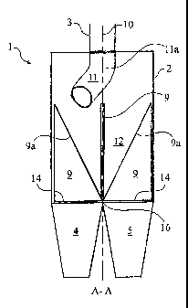
Dispositif (1) permettant de partager un écoulement de matières particulaires ou pulvérulentes en au moins deux sous-écoulements. Ledit dispositif comprend les éléments suivants : un logement (2) pourvu d'un conduit d'entrée pratiquement vertical (3) et d'un ou plusieurs conduits de sortie (4,5,6,7) provenant d'ouvertures séparées, et cloisonné par des parois (9) s'étirant en direction radicale jusqu'à la ligne médiane du conduit d'entrée (3) ; un rotor (11) situé dans le prolongement immédiat du conduit d'entrée (3), dont l'axe de rotation coïncide avec la ligne médiane (10) du conduit d'entrée, ledit rotor (11) ayant une surface à configuration radiale (11a) permettant de guider l'écoulement des matières en direction radiale vers l'extérieur dans l'espace libre (12) situé au-dessus des conduits de sortie. Le dispositif présente la particularité d'avoir des parois de cloisonnement radiales (9) ajustables en direction périphérique. Il en résulte un rapport que l'on peut varier librement entre un nombre arbitraire de sous-écoulements de sortie.


Abrégé anglais


Abstract Described is a device (1) for dividing a stream of particulate or
pulverulent material into at least two substreams, said device comprising a
housing (2) with a substantially vertical inlet duct (3) and two or more
outlet ducts (4, 5, 6, 7) emanating from separate openings, and being
separated by means of partition walls (9) extending radially relative to the
centreline of the inlet duct (3), and a rotor 11) which is located in
immediate extension of the inlet duct (3), with its axis of rotation
coinciding with the centreline (10) of the inlet duct, said rotor (11) having
a radially configured surface (11a) for directing the falling material stream
radially outwards into the free space (12) above the outlet ducts. The device
is peculiar in that the radial partition walls (9) can be adjusted in the
circumferential direction. The result will be a freely variable ratio between
an arbitrary number of outlet substreams.

Revendications

Note : Les revendications sont présentées dans la langue officielle dans laquelle elles ont été soumises.


6
Claims
1. Device (1) for dividing a stream of particulate or pulverulent material
into at
least two substreams, said device comprising a housing (2) with a
substantially
vertical inlet duct (3) and two or more outlet ducts (4, 5, 6, 7) emanating
from
separate openings, and being separated by means of partition walls (9)
extending radially relative to the centreline of the inlet duct (3), and a
rotor 11)
which is located in immediate extension of the inlet duct (3), with its axis
of
rotation coinciding with the centreline (10) of the inlet duct, said rotor
(11) having
a radially configured surface (11a) for directing the falling material stream
radially
outwards into the free space (12) above the outlet ducts, characterized in
that
the radial partition walls (9) can be adjusted in the circumferential
direction.
2. Device (1) according to claim 1, characterized in that the partition walls
(9)
are made up of plates, with each plate pivotally mounted around its separate
radial axis (14).
3. Device (1) according to claim 2, characterized in that each of the plates
(9) is
pivotally mounted at its lower side edge (14) so that each plate (9) is
pointing
upwards into the free space (12) above the outlet ducts and being displaceable
in
the transverse direction by angular turning of the plate.
4. Device (1) according to claim 2, characterized in that the free end edge or
knife edge (9a) of each of the plates is configured so that it virtually
proceeds
through the point (16) where the axes (14) of rotation of the plates (9)
intersect
the axis (10) of rotation of the rotor.

Description

Note : Les descriptions sont présentées dans la langue officielle dans laquelle elles ont été soumises.


CA 02509457 2005-06-09
WO 2004/101402 PCT/IB2004/000689
1
DEVICE FOR DIVIDING A STREAM OF PARTICULATE OR PULVERULENT
MATERIAL INTO SUBSTREAMS
The present invention relates to a device for dividing a stream of particulate
or
pulverulent material into at least two substreams, said device comprising a
housing with a substantially vertical inlet duct and two or more outlet ducts
emanating from separate openings, and being separated by means of partition
walls extending radially relative to the centreline of the inlet ducfi, and a
rotor
which is located in immediate extension of the inlet duct, with its axis of
rotation
coinciding with the centreline of the inlet duct, said rotor having a radially
configured surface for directing the falling material stream radially outwards
into
the free space above the outlet ducts.
A device of the aforementioned kind is known from DE 295 00 305 U1. This
known device is designed for dividing a material stream into several
substreams
according to a predetermined distribution ratio. The device may comprise
radial
partition walls, with the mutual circumferential distance of these partition
walls
being the main determinant of this predetermined distribution ratio. The
disadvantage of this known device is that the distribution ratio between the
individual
substreams is not directly variable on a continuous basis during operation,
but
will as a minimum necessitate a temporary shutdown of operation. For example,
from the viewpoint of process optimization, the provision of such means
allowing
for continuous variability of the distribution ratio would be desirable.
It is the objective of the present invention to provide a device for dividing
a
material stream into several substreams whereby the aforementioned
disadvantage is remedied.
According to the invention this is achieved by means of a device of the kind
mentioned in the introduction, and being characterized in that the radial
partition
walls can be adjusted in the circumferential direction.

CA 02509457 2005-06-09
WO 2004/101402 PCT/IB2004/000689
2
The result will be a freely variable ratio between an arbitrary number of
outlet
substreams.
The partition walls may be configured in any suit2~ble manner. In one
embodiment they may thus be formed as a roof ridge with inclined surFaces
sloping towards separate outlet ducts, being displaceable in the
circumferential
direction.
It is, however, preferred that the partition walls are made up of plates, with
each
plate pivotally mounted around its separate radial axis. In this embodiment,
each
of the plates may be pivotally mounted at its lower side edge so that each
plate is
pointing upwards into the free space above the outlet ducts and being
displaceable in the transverse direction by angular turning of the plate.
Hence the
one free end edge of each of the plates will constitute the knife edge of each
of
the partition walls, where the mutual distance between the knife edges will,
due
to the angular turning of the plates, be the main determinant of the
distribution
ratio between the substreams.
In an advantageous embodiment the aforementioned free end edge or knife
edge of each of the plates is configured so that it virtually proceeds through
the
point where the axes of rotation of the plates intersect the axis of rotation
of the
rotor. Hence two adjacent plates can be angularly adjusted so that their knife
edges bear against one another, entailing complete shutting-off of the
underlying
outlet duct. Furthermore, in this embodiment the knife edges will intersect
the
material stream under the same angular span viewed from the top, regardless of
how far the material is ejected into the free space by the rotor.
The invention is described in further details in the following with reference
to the
drawing, being diagrammatic, and where
Fig. 1 shows partly as a sectional view a side view of a preferred embodiment
of
the device according to the invention, and

CA 02509457 2005-06-09
WO 2004/101402 PCT/IB2004/000689
3
Fig. 2 shows the device shown in Fig. 1 viewed from above.
In Fig. 1 and 2 is shown a preferred embodiment for a device 1 according to
the
invenfiion. The device 1 comprises a housing 2 with an inlet dcac$ 3 and four
outlet
ducts 4., 5, 6 and 7, emanating from separate openings, and being separated by
means of partition walls 9 extending radially relative to the centreline 10 of
the
inlet duct. The device 1 also comprises a rotor 11 which is fitted in
immediate
extension of the inlet duct 3, with its axis of rotation coinciding with the
centreline
of the inlet duct. The rotor 11 comprises a radially proceeding pipe section
11 a
1o which during the operation of the device directs the falling material
stream
radially outwards into the free space 12 above the outlet ducts. The rotor 11
also
comprises an outermost pipe section 11 b, which, viewed in the rotational
direction of the rotor, is pointing backward in a partially tangential
direction.
Hence, the rotor 11 will rotate solely on the strength of the impulse imparted
from
the falling material. As indicated in Fig. 2 at the dotted circle 13 the
material will
be ejected into the free space 12 along a circular path, the radius of which
is
dependent on the rotational speed of the rotor and hence, in the shown
embodiment, the volume flow through the pipe. The rotor 11 may alternatively
be
driven by means of a motor, not shown.
In order to divide the material stream leaving the rotor 11 into four
substreams
with a mutually variable volume ratio, the radial partition walls 9 are made
up of
plates each of which is pivotally mounted about its separate radial axis 14,
thus
being adjustable in the circumferential direction. As is apparent from the
drawing,
the plates 9 are pivotally mounted at their lower side edges so that the
plates 9
point upwards into the free space 12 above the outlet ducts and being
displaceable in the transverse direction by angular turning of the plates 9.
Hence,
the one free end of each of the plates 9 constitute the knife edges 9a of the
partition walls, where the mutual distance between the knife edges will, due
to
the angular turning of the plates, be the main determinant of the distribution
ratio
between the substreams.

CA 02509457 2005-06-09
WO 2004/101402 PCT/IB2004/000689
4
In the shown embodiment, the free end edge or knife edge 9a of each of the
plates 9 is configured so that it virtually extends through a point 16, where
the
axes of rotation of the plates 9 intersect the axis of rotation 10 of the
rotor.
Hence, two adjacent plates g can be angularly turned so that (heir lenife
edges 9a
bear against one another, thereby completely shutting off the underlying
outlet
duct. Furthermore, in this embodiment the knife edges will intersect the
material
stream at the same angular span viewed from fibs top, regardless of how far
the
material is ejected into the free space by the rotor.
The angular turning of the plates 9 may in a simple embodiment be done
manually by means of a handle, not shown, fixed to the shafts 14, but may also
be done automatically by means of remote-controlled means, not shown.
In the shown embodiment, the housing 2 has a substantially quadratic cross-
section. The invention is not limited to this embodiment and the housing 2 may
thus assume any appropriate form, whether circular, polygonal etc.
In actual practice, the exact configuration of the device will depend on the
specific requirements which apply for dividing the material stream. These
2 0 requirements will typically relate to the number of substreams into which
the
material is to be divided, the distribution ratio between the substreams, and
the
intervals within which it must be possible to regulate the individual
substreams.
The device shown on the drawing comprises a total of four outlet ducts which
are
separated by means of four adjustable plates 9. When all plates 9 are in
vertical
position, as shown in Fig. 1, the material stream will be divided into four
substreams, each constituting 25 per cent of the total stream. In Fig. 2 all
the
plates 9 are shown in a position which is angularly turned away from the
vertical
position. In the shown embodiment, one substream may be reduced to 0 % by
3 o altering the angular position of the two plates 9, constituting the
boundary against
the respective outlet duct, across this outlet duct, thus blocking completely
the
duct for fall-through of material so that the material will be directed to the
two
adjacent outlet ducts. In similar fashion, a substream can be increased to 50
per

CA 02509457 2005-06-09
WO 2004/101402 PCT/IB2004/000689
cent by altering the angular position of the two plates 9 forming the boundary
against the respective outlet duct across the two adjacent outlet ducts,
thereby
partially blocking these ducts for fall-through of material so that instead
the
material is diverted to the mentioned outlet duct.
5
In certain instances, it will be desirable to divide the material stream into
only
three substreams, of which it must be possible to regulate one substream
within
the range 0 -100% and to regulate the two other substreams within the range 0
- 50%. If this is the case, two outlet ducts can be converged to form one
single
duct. For example, this may be accomplished by using the device indicated on
the drawing, where two diagonally opposed outlet ducts, such as for example
the
outlet ducts 4 and 6, are converged into one single duct.

Dessin représentatif
Une figure unique qui représente un dessin illustrant l'invention.
États administratifs

2024-08-01 : Dans le cadre de la transition vers les Brevets de nouvelle génération (BNG), la base de données sur les brevets canadiens (BDBC) contient désormais un Historique d'événement plus détaillé, qui reproduit le Journal des événements de notre nouvelle solution interne.

Veuillez noter que les événements débutant par « Inactive : » se réfèrent à des événements qui ne sont plus utilisés dans notre nouvelle solution interne.

Pour une meilleure compréhension de l'état de la demande ou brevet qui figure sur cette page, la rubrique Mise en garde , et les descriptions de Brevet , Historique d'événement , Taxes périodiques et Historique des paiements devraient être consultées.

Historique d'événement

Description Date
Le délai pour l'annulation est expiré 2018-02-26
Requête pour le changement d'adresse ou de mode de correspondance reçue 2018-01-12
Lettre envoyée 2017-02-27
Accordé par délivrance 2011-08-02
Inactive : Page couverture publiée 2011-08-01
Inactive : Taxe finale reçue 2011-05-13
Préoctroi 2011-05-13
Un avis d'acceptation est envoyé 2011-01-07
Lettre envoyée 2011-01-07
Un avis d'acceptation est envoyé 2011-01-07
Inactive : Approuvée aux fins d'acceptation (AFA) 2011-01-04
Lettre envoyée 2008-12-15
Modification reçue - modification volontaire 2008-10-31
Exigences pour une requête d'examen - jugée conforme 2008-10-31
Toutes les exigences pour l'examen - jugée conforme 2008-10-31
Requête d'examen reçue 2008-10-31
Déclaration du statut de petite entité jugée conforme 2007-10-09
Inactive : CIB de MCD 2006-03-12
Inactive : Page couverture publiée 2005-09-06
Inactive : Notice - Entrée phase nat. - Pas de RE 2005-09-01
Lettre envoyée 2005-09-01
Demande reçue - PCT 2005-07-19
Exigences pour l'entrée dans la phase nationale - jugée conforme 2005-06-09
Demande publiée (accessible au public) 2004-11-25

Historique d'abandonnement

Il n'y a pas d'historique d'abandonnement

Taxes périodiques

Le dernier paiement a été reçu le 2011-01-19

Avis : Si le paiement en totalité n'a pas été reçu au plus tard à la date indiquée, une taxe supplémentaire peut être imposée, soit une des taxes suivantes :

  • taxe de rétablissement ;
  • taxe pour paiement en souffrance ; ou
  • taxe additionnelle pour le renversement d'une péremption réputée.

Veuillez vous référer à la page web des taxes sur les brevets de l'OPIC pour voir tous les montants actuels des taxes.

Historique des taxes

Type de taxes Anniversaire Échéance Date payée
Taxe nationale de base - générale 2005-06-09
Enregistrement d'un document 2005-06-09
TM (demande, 2e anniv.) - générale 02 2006-02-27 2006-01-18
TM (demande, 3e anniv.) - générale 03 2007-02-26 2007-01-17
TM (demande, 4e anniv.) - petite 04 2008-02-25 2008-01-11
Requête d'examen - générale 2008-10-31
TM (demande, 5e anniv.) - générale 05 2009-02-25 2009-01-08
TM (demande, 6e anniv.) - générale 06 2010-02-25 2010-01-15
TM (demande, 7e anniv.) - générale 07 2011-02-25 2011-01-19
Taxe finale - générale 2011-05-13
TM (brevet, 8e anniv.) - générale 2012-02-27 2012-01-16
TM (brevet, 9e anniv.) - générale 2013-02-25 2013-01-09
TM (brevet, 10e anniv.) - générale 2014-02-25 2014-01-08
TM (brevet, 11e anniv.) - générale 2015-02-25 2015-02-04
TM (brevet, 12e anniv.) - générale 2016-02-25 2016-02-04
Titulaires au dossier

Les titulaires actuels et antérieures au dossier sont affichés en ordre alphabétique.

Titulaires actuels au dossier
F.L. SMIDTH A/S
Titulaires antérieures au dossier
MOGENS JUHL FOENS
NIELS OLE CEDERGAARD
Les propriétaires antérieurs qui ne figurent pas dans la liste des « Propriétaires au dossier » apparaîtront dans d'autres documents au dossier.
Documents

Pour visionner les fichiers sélectionnés, entrer le code reCAPTCHA :


Pour visualiser une image, cliquer sur un lien dans la colonne description du document. Pour télécharger l'image (les images), cliquer l'une ou plusieurs cases à cocher dans la première colonne et ensuite cliquer sur le bouton "Télécharger sélection en format PDF (archive Zip)" ou le bouton "Télécharger sélection (en un fichier PDF fusionné)".

Liste des documents de brevet publiés et non publiés sur la BDBC .

Si vous avez des difficultés à accéder au contenu, veuillez communiquer avec le Centre de services à la clientèle au 1-866-997-1936, ou envoyer un courriel au Centre de service à la clientèle de l'OPIC.


Description du
Document 
Date
(aaaa-mm-jj) 
Nombre de pages   Taille de l'image (Ko) 
Revendications 2005-06-09 1 43
Abrégé 2005-06-09 2 69
Description 2005-06-09 5 249
Dessin représentatif 2005-06-09 1 7
Dessins 2005-06-09 1 16
Page couverture 2005-09-06 2 46
Dessin représentatif 2011-06-30 1 6
Page couverture 2011-06-30 2 47
Avis d'entree dans la phase nationale 2005-09-01 1 193
Courtoisie - Certificat d'enregistrement (document(s) connexe(s)) 2005-09-01 1 104
Rappel de taxe de maintien due 2005-10-26 1 109
Rappel - requête d'examen 2008-10-28 1 127
Accusé de réception de la requête d'examen 2008-12-15 1 176
Avis du commissaire - Demande jugée acceptable 2011-01-07 1 164
Avis concernant la taxe de maintien 2017-04-10 1 178
PCT 2005-06-09 2 74
Taxes 2006-01-18 1 28
Taxes 2007-01-17 1 29
Taxes 2008-01-11 1 31
Taxes 2009-01-08 1 36
Taxes 2010-01-15 1 36
Taxes 2011-01-19 1 37
Correspondance 2011-05-13 1 35