Note : Les descriptions sont présentées dans la langue officielle dans laquelle elles ont été soumises.
CA 02510588 2005-06-16
WO 2004/060742 PCT/US2003/039795
FLOTATION DEVICE
CROSS REFERENCES TO RELATED APPLICATIONS
[0001] Not Applicable
STATEMENT REGARDING FEDERALLY SPONSORED RESEARCH
[0002] Not Applicable
BACKGROUND OF THE INVENTION
[0003] The field of invention is flotation devices, and more particularly,
self
inflating flotation devices attachable to objects.
[0004] Nonfloating objects which are used in the vicinity of bodies of water,
such
as shotguns used for duck hunting, can fall into the water and sink to the
bottom of the
body of water. If the water is very murky or deep, the shotgun can be lost
forever.
Flotation devices, such as life vests, are provided for individuals operating
in the
vicinity of bodies of water. Unfortunately, due to the shape of these life
vests, they are
not adaptable for use with objects, such as shotguns, and other nonfloating
objects.
[0005] Flotation devices have been developed for use with submerged articles,
such as disclosed in U.S. Pat. No. 6,036,559, which include an inflatable
balloon
stuffed in a casing with a water actuated valve and compressed gas cartridge.
The
casing is directly attached to the object, such as a fishing pole. When the
fishing pole
falls into the water, the balloon inflates and ejects a cap enclosing the
balloon in the
casing. The inflated balloon rises to the water surface while the cap falls to
the bottom
of the body of water. As a result, the single purpose device can only be used
once.
1
CA 02510588 2005-06-16
WO 2004/060742 PCT/US2003/039795
[0006] Another similar device disclosed in U.S. Pat. No. 5,857,881 discloses
flotation device specifically for fishing rods. This device also includes a
hard case for
holding the contain flotation device components which inherently prevents
inadvertent actuation. Unfortunately, the hard case increases the device cost.
[0007] In addition to the above deficiencies in both of the above described
flotation devices for objects, the prior art devices merely add weight to the
fishing rod,
and are of no use until the user makes a mistake and drops the fishing rod in
the water.
As a result, if the user is fortunate, the device is never used. Therefore, a
flotation
device which provides utility other than in adversity would be further
advantageous.
BRIEF SUMMARY OF THE INVENTION
[0008] The present invention provides a flotation device for use with objects.
The
device includes a bladder forming part of an inflatable assembly having an
inflatable
volume defined by a first wall and a second wall sealed about a periphery. A
water
actuated inflation valve is in fluid communication with the inflatable volume
through
at least one of the walls, and the inflatable assembly wraps over the water
actuated
inflation valve to form a protective cavity covering the water actuated
inflation valve.
At least one releasable fastener holds the inflatable assembly over the water
actuated
valve, wherein actuation of the water actuated valve inflates the bladder to
release the
at least one releasable fastener to allow the bladder to further expand. In
one
embodiment, at least one strap is fixed to the inflatable assembly.
[0009] A general objective of the present invention is to provide a flotation
device
which does not include a hard case enclosing the flotation device components
to
2
CA 02510588 2005-06-16
WO 2004/060742 PCT/US2003/039795
prevent inadvertent actuation of the device. This objective is accomplished by
providing a flotation device having an inflatable assembly which wraps over
the water
actuated valve to prevent inadvertent actuation.
[0010] Another objective of the present invention is to provide a flotation
device
which provides utility beyond that of a typical flotation device. This
objective is
accomplished by providing at least one strap fixed to the inflatable assembly
which is
connectable to the object to provide a sling or handle for carrying the
object.
[0011] The foregoing and other objectives and advantages of the invention will
appear from the following description. In the description, reference is made
to the
accompanying drawings which form a part hereof, and in which there is shown by
way of illustration a preferred embodiment of the invention.
BRIEF DESCRIPTION OF THE DRAWINGS
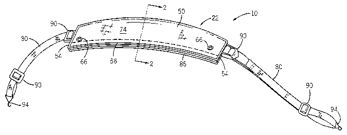
[0012] Fig. 1 is a perspective view of an inflatable device incorporating the
present invention;
[0013) Fig. 2 is a cross sectional view along line 2-2 of Fig. l;
[0014] Fig. 3 is bottom view of the inflatable device of Fig. 1 in an
unwrapped
position;
[0015) Fig. 4 is a detailed view of the water actuated valve of Fig. 3;
[0016) Fig. 5 is a cross sectional view of the fill tube of Fig. 4;
[0017] Fig. 6 is an alternative inflatable assembly incorporating the present
invention;
3
CA 02510588 2005-06-16
WO 2004/060742 PCT/US2003/039795
[0018] Fig. 7 is an alternative flotation device incorporating the present
invention;
[0019] Fig. 8 is bottom view of another alternative inflatable assembly in an
unwrapped position incorporating the present invention; and
[0020] Fig. 9 is bottom view of yet another alternative inflatable assembly in
an unwrapped position incorporating the present invention.
DETAILED DESCRIPTION OF THE PREFERRED EMBODIMENTS
[0021] A flotation device 10 shown in Figs 1-5 is attachable to an object,
such
as sporting equipment, a backpack, cooler, tackle box, and the like, which can
inadvertently fall into a body of water automatically inflates to facilitate
retrieval of
the object from the water. The flotation device 10 includes a water actuated
valve 12
which releases a compressed gas into an inflatable bladder 14 to either raise
the object
close to the water surface or identify the location of the object in the
water. The
flotation device 10 can form part of a sling which can be used to carry the
object.
[0022] The flotation device 10 includes the flexible inflatable bladder 14
having an inner wall 18 and an outer wall 20 forming part of an inflatable
assembly
22. The inner wall 18 includes a gas impervious sheet of material, such as a
heat
sealable urethane coated nylon. The outer wall 20 includes a gas impervious
sheet of
material facing the inner wall 18, and is joined to the inner wall 18 about a
periphery
defined by a seam 24 joining the two walls 18, 20 to form an inflatable volume
26
therebetween. Preferably, the walls 18, 20 are formed from the same material
and
joined at the seam 24 using methods known in the art, such as RF welding, heat
sealing, and the like, which forms an air tight seal joining the two walls 18,
20.
CA 02510588 2005-06-16
WO 2004/060742 PCT/US2003/039795
[0023] A fitting 28 providing a fluid passageway into the inflatable volume 26
extends through a fill opening 30 formed in the inner wall 18. The fitting 28,
such as a
brass manifold valve available from Halkey-Roberts Corporation in St.
Petersburg,
Florida, includes a fill tube 32 having a flange 34 disposed inside the
inflatable
volume 26 and sealingly joined to an inner surface 36 of the inner wall 18.
The flange
34 is sealingly joined to the inner wall 18, using methods such as RF welding,
heat
sealing, and the like, to prevent gas from escaping from the inflatable volume
26
through the opening 30.
[0024] The fill tube 32 extends through the fill opening 30 out of the
inflatable volume 26, and is received in a through hole 38 formed in the water
actuated valve 12 for receiving the tube 32 in fluid communication with
released
compressed gas. A threaded cap 40 threadably received in the fill tube end
clamps the
valve 12 onto the tube 32. Of course, the valve 12 can be directly sealingly
joined to
the fill opening 30 without departing from the scope of the invention.
[0025] As shown in Fig. 2, the inflatable assembly 22 wraps over the water
actuated valve 12 joined to the inner wall 18 to form a protective cavity 42
which
protects the valve 12 from incidental contact with water. Preferably, the
bladder 14 is
folded in half over the valve 12 to form the protective cavity 42. The bladder
14,
however, can be rolled, folded in thirds, and the like, to wrap over the valve
12 and
form the protective cavity 42 without departing from the scope of the
invention.
[0026] The water actuated valve 12 can be any valve knOWl1 lIl the art which
is
in fluid communication with the inflatable volume 26 through the fill opening
30 to
inflate the bladder 14 upon immersion of the flotation device 10 in water.
Preferably,
CA 02510588 2005-06-16
WO 2004/060742 PCT/US2003/039795
the valve 12 is a commercially available valve, such as an auto inflator
assembly
available from Hallcey-Roberts Corporation. Preferably, the valve 12 includes
a source
of compressed gas, such as a C02 cartridge 44, coupled to a valve 12, and the
COa
cartridge 44 is pierced to release the gas into the inflatable volume 26 upon
immersion
of the valve 12 in water. As is laiown in the art, the C02 ca.uridge 44 can be
threadably coupled to the valve 12 for easy replacement of a spent cartridge.
[0027] A dump valve 48 in fluid communication with the inflatable volume 26
provides an exhaust path for compressed gas in the inflatable volume 26. The
dump
valve 48 sealingly extends through the bladder inner wall 18, and is
selectively opened
by the user to deflate the bladder 14 after it has been inflated and the
object retrieved
from the water. Preferably, the dump valve 48 is a commercially available
valve such
as available from Hallcey-Roberts Corporation. Although porting the dump valve
48
through the inner wall 18 is preferred, the dump valve 48 can be in fluid
communication with the inflatable volume 26 through the bladder outer wall 20
without departing from the scope of the invention.
[0028] A flexible cover 50 is joined to the bladder 14 to form part of the
inflatable assembly 22 and protect the bladder 14 from damage. The cover 50
can be
joined to the bladder 14 using methods lalown in the art, such as the methods
described above for joining the bladder inner and outer walls 18, 20 together,
and
fuuther including joining the cover 50 to excess bladder material 52 not
defining the
inflatable volume 26 such as by sewing, releasable fasteners, adhesives, and
the like
without departing from the scope of the invention.
6
CA 02510588 2005-06-16
WO 2004/060742 PCT/US2003/039795
[0029] The cover 50 can be any suitable material, such as fabric, leather,
plastic, and the like, which can protect the bladder 14. Preferably, the cover
50 is
rectangular having opposing ends 54 joined by sides 56 which extend past the
bladder
periphery 58 and define edges of the protective cavity 42. Although a
rectangular
cover 50 is preferred, the cover 50 can have any shape, such as circular,
oval,
polygonal, and the like with straight and/or curved edges, or deleted
completely
without departing from the scope of the invention.
[0030] The edges 54, 56 of the protective cavity 26 are held together by
releasable fasteners 64 which hold the bladder 14 over the water actuated
valve 12
until the bladder 14 begins to inflate. Preferably, the releasable fasteners
64 are hook
and loop fasteners, such as Velcro", which releasably attaches the edges 54,
56 of the
protective cavity 42 together. Hoolc and loop fasteners are preferred,
however, other
releasable fasteners can be used, such as snaps, releasable adhesives,
breakable
threads, and the like without departing from the scope of the invention.
Although a
plurality of fasteners 64 is shown, only one releasable fasteners is required
to secure
the protective cavity 42 over the water actuated valve 12.
[0031] The releasable fasteners 64 are preferably fixed proximal the edges 54,
56 of the cover, such that the fasteners 64 are engaged when the inflatable
assembly
22 wraps over the water actuated valve 12. Of course, if the cover 50 is not
provided,
the releasable fasteners 64 can be fixed to the bladder 14. Although
releasably
securing all of the free edges 54, 56 of the protective cavity 42 using a
plurality of
releasable fasteners 64 is disclosed, as shown in Fig. 6 some free edges of
the
protective cavity 42, such as the cover ends 56, can be permanently joined
together,
7
CA 02510588 2005-06-16
WO 2004/060742 PCT/US2003/039795
such as by sewing, RF welding, heat sealing, and the like, without departing
from the
scope of the invention, as long as the protective cavity 42 can be opened to
allow
expansion of the inflatable bladder 14.
[0032] Inflation of the bladder 14 (i.e. the release of compressed gas into
the
inflatable volume 26) forces the releasable fasteners 64 to open and allow the
bladder
14 to expand. Of course, the location of the releasable fasteners 64 on, or
around, the
inflatable assembly 22 depends upon the manner in which the inflatable
assembly 22
wraps over the water actuated valve 12.~For example, if the inflatable
assembly 22 is
folded in half over the valve 12, the releasable fasteners 64 can be fixed to
the inner
surface 72 of the cover 50. If the inflatable assembly 22 is folded in thirds,
or rolled,
over the water actuated valve 12, releasable fastener 64 can be fixed to both
an inner
and outer surface 72, 74 of the cover 50 or the inner and outer walls 18, 20
of the
bladder 15 if a cover 50 is not provided.
[0033] An actuation opening 66 formed through the inflatable assembly 22
provides a water passageway for water into the protective cavity 42.
Preferably, the
opening 66 is defined by a small grommet (i.e. a grommet that is less than .5
inches in
diameter) fixed to the cover 50 adjacent the inflatable bladder 14. Of course,
if the
protective cavity 42 is not tightly sealed by the releasable fasteners 64,
water can
easily enter the protective cavity 42 when the inflatable assembly 22 is
immersed in
the water, and the opening 66 is not required. Although two actuation openings
66
through the cover 50 are shown, one or more actuation openings 66 can be
provided
depending upon the desired response time of the water actuated valve 12 to
immersion
of the flotation device 10 in the water.
8
CA 02510588 2005-06-16
WO 2004/060742 PCT/US2003/039795
[0034] A protective material 68- interposed between the bladder inner wall 18
and water actuated valve 12 protects the bladder inner wall 18 from damage due
to the
cold temperatures caused by rapid release of the compressed gas through the
valve 12
upon immersion of the valve 12 in water. The protective material 68 is
preferably
formed from a heat sealable urethane and joined to a portion of the inner wall
18
surrounding the fill opening 30 using the above disclosed methods known in the
art.
Of course, other methods for protecting the inner wall 1.8 from damage caused
by the
cold temperatures can be provided, such as by slipping a water permeable sock
(not
shown) over the valve 12 which thermally separates the valve 12 from bladder
inner
wall 18, providing a cover, or strip of material, over the bladder inner wall
18 which
thermally separates the valve 12 from the inner wall 18, and the like, without
departing from the scope of the invention.
[0035] Reflective material 70 joined to the inflatable assembly 22 inside the
protective cavity 42, such as on an exterior surface 78 of the bladder inner
wall 18 or
the inner surface 72 of the cover 50, is exposed when the flotation device 10
is
immersed in water and the bladder 14 inflates. The reflective material 70 can
be
reflective tape, heat sealable reflective material, and the like joined to the
inflatable
assembly 22, without departing from the scope of the invention.
Advantageously, the
exposed reflective material 70 reflects light, such as from a flashlight, when
the
flotation device 10 is dropped in the water in low light conditions. Of
course,
reflective material 70 can also be provided on an exterior surface of the
inflatable
assembly 22, such as an exterior surface 74 of the cover 50 (shown in Fig. 6)
to
enhance visibility of the user transporting the flotation device 10.
9
CA 02510588 2005-06-16
WO 2004/060742 PCT/US2003/039795
[0036] Straps 80, such as formed from nylon webbing, leather, fabric, and the
like, fixed to the inflatable assembly 22 are attachable to the object.
Advantageously,
the straps 80 form part of a sling or handle for carrying the object, such as
a shot gun.
Preferably, the straps 80 are provided with sufficient length, such that the
flotation
device 10 can be used as a sling connected to the object which can be
supported by the
user's shoulder when carrying the object using the flotation device 10.
Buckles 90 are
provided to adjust the strap length, as desired by the user. Hooks 94, loops,
or other
fastening devices known in the art, are fixed to the free ends of the straps
for
connecting to the object.
[0037] The straps 80 can be fixed directly to the cover 50 or bladder 14, such
as by sewing, RF welding, heat sealing, and the like. Although a pair of
straps 80 is
shown, only one strap can be used without departing from the scope of the
invention.
If one strap 80 is used, the one strap can have one end fixed to the
inflatable assembly
22 and an opposing end available for connection to the object, or the one
strap can be
fixed to the inflatable assembly between the two strap ends which are both
connectable to the object.
[0038] In an alternative embodiment shown in Fig. 7, the straps 80 are
connected to the inflatable assembly using grommets 82 forming through holes
84 in
the cover 50 or excess bladder material 52 (shown in Fig. 8) not defining the
inflatable
volume 26. The straps 80 are fixed to the inflatable assembly 22 using
fasteners 88,
such as~hooks, bolts, rivets, or other engagement devices, which can fix the
straps 80
to the inflatable assembly 20 through the through holes 84.
CA 02510588 2005-06-16
WO 2004/060742 PCT/US2003/039795
[0039] Referring back to Figs. 1 and 2, padding 86 fixed to the exterior
surface 74 of the cover 50 can be provided to reduce the strain on the user's
shoulder
supporting the object using the flotation device 10. The.padding 86 can be any
cushioning material, such as a compressible material, foam, fabric stuffing,
and the
like. Of course, the pad 86 can be fixed to the strap 80, or anywhere in or on
the
inflatable assembly 22, to reduce the strain on the user carrying the object
using the
flotation device 10 without departing from the scope of the invention.
[0040] In use, the flotation device 10 is attached to the object, such as a
shotgun, using the straps 80. When the shotgun falls into the body of water
and the
flotation device 10 is immersed in the water, the water seeps into the
protective cavity
42 covering the water actuated valve 12 past the releasable fasteners 64 and
through
the actuation opening 66. The water actuates the water actuation valve 12 to
release
the compressed gas from the compressed gas cartridge 44 into the inflatable
volume
26 which inflates the bladder 14. The inflating bladder 14 causes the
releasable
fasteners 66 to releases and allow further expansion of the bladder 14 which
exposes
the reflective material 70
[0041] Once the bladder 14 has inflated sufficiently to provide sufficient
buoyancy to begin rising to the surface of the water, the bladder 14 rises to
the water
surface for retrieval of the shotgun by the user. The flotation device 10 can
be reused
by replacing the expended compressed gas cartridge 44, recovering the water
actuated
valve 12 in the protective cavity 42, and refastening the releasable fasteners
66 at the
protective cavity edges 52, 54.
11
CA 02510588 2005-06-16
WO 2004/060742 PCT/US2003/039795
[0042] In an alternative embodiment, disclosed in Figs. 9, tabs 82 forming
part
of the inflatable assembly extend from the bladder 14 for attachment to straps
and/or a
cover. The releasable fasteners could also be fixed to the tabs 82 to
releasably fasten
the protective cavity over the water actuated valve 12. Preferably, the tabs
82 are
formed in excess bladder material 52 not defining the inflatable volume.
Through
holes 92 can be formed in the tabs 82 to facilitate comiecting the tabs to the
cover,
straps, or releasable fasteners. Of course, if a cover 50, such as disclosed
above, is
provided, the tabs 82 can be formed as, or fixed to, part of the cover without
departing
from the scope of the invention.
[0043] While there have been shown and described what is at present
considered the preferred embodiments of the invention, it will be obvious to
those
skilled in the art that various changes and modifications can be made therein
without
departing from the scope of the invention defined by the appended claims.
12