Note : Les descriptions sont présentées dans la langue officielle dans laquelle elles ont été soumises.
CA 02511936 2005-O1-25
WO 2004/054013 PCT/US2003/023759
"FEEDFORWARD CONTROL PROCESSES FOR VARIABLE
OUTPUT HYDROGEN GENERATORS"
CROSS-REFERENCE TO RELATED APPLICATION
[0001] This application is a Continuation-In-Part of copending Application
Serial
No. 10/209,486 filed July 30, 2002, the contents of which are hereby
incorporated by
reference.
FIELD OF THE INVENTION
[0002] This invention pertains to processes for operating variable output
hydrogen
generators and integrated hydrogen generator/fuel cell systems. The processes
include
to control processes that enable rapid transitions to reflect changes in
output demand
BACKGROUND OF THE INVENTION
[0003] Fuel cells convert hydrogen and oxygen to water, releasing energy as
usable
electricity without employing combustion as an intermediate step.
Unfortunately, the use
of fuel cells has been limited especially where a rapid change in electricity
demand is
required such as in residential applications. The problem is that the rate of
hydrogen
supply to the fuel cell must rapidly change in order to accommodate varying
electrical
loads.
[0004] One could use a reservoir of hydrogen from which to supply the fuel
cell, and
the replenishment of hydrogen to the reservoir would therefore not be
subjected to
accommodating the rapid changes in hydrogen demand. However, such a solution
is
impractical, especially for residential use, due to difficulties and risks
associated with
such storage. Moreover, hydrogen storage equipment adds to the size and cost
thereby
reducing the attractiveness of a fuel cell for residential use. Alternatively,
electricity
could be stored in batteries, which serve as a buffer between the fuel cell
system and the
electrical load. Batteries, especially of the volume required to meet the
needs of
residential units, also add to the cost and size of the fuel cell system.
Moreover, batteries
have a limited life and must be replaced. Another approach is to store
electricity in a
super capacitor. While the size and cost of a super capacitor may be
attractive, the
disadvantage is the limited storage capacity.
-1-
CA 02511936 2005-O1-25
WO 2004/054013 PCT/US2003/023759
[0005] Ideally, hydrogen would be generated on-site on an as needed basis for
the
fuel cell by the reforming (e.g., steam reforming and autothermal reforming)
of fuels
such as methanol, ethanol, natural gas, propane, butane, gasoline and diesel.
Such fuels
have high energy storage densities, have conventional storage protocols and
have a
nationwide supply infrastructure.
[0006] Although technology exists for the generation of hydrogen by reforming
fuels,
the implemented production processes are not able to quickly change the rate
of hydrogen
generation so as to be useful in a residential fuel cell application. For
instance, hydrogen
is widely produced for chemical and industrial purposes by converting suitable
fuel
to material in a reforming process to produce a synthesis gas. Such chemical
and industrial
production usually takes place in large facilities that operate under steady-
state
conditions.
[0007] On-site hydrogen supply for fuel cells used in smaller mobile and
stationary
facilities, including residential-scale facilities, poses substantial problems
even without
15 the added complexities of operating at varying production rates. For
instance, hydrogen
generators for fuel cells must be smaller, simpler and less costly than
hydrogen plants for
the generation of industrial gases. Furthermore, hydrogen generators for use
with fuel
cells will need to be integrated with the operation of the fuel cell such that
energy storage
requirements are minimized. Moreover, the hydrogen generators must in
combination
2o with the fuel cells, be economically viable both in terms of purchase cost
and cost of
operation, and they must be sufficiently compact to meet consumer desires.
[0008] The challenge associated with providing smaller scale hydrogen
generators is
readily apparent from the number of unit operations required to convert fuel
to hydrogen
suitable for use in a fuel cell. The fuel must be brought to temperatures
suitable for
25 reforming which are often in excess of 600°C. The fuel is reformed
to produce hydrogen
and carbon monoxide, and the reformate is subjected to water gas shift at
lower
temperatures to convert carbon monoxide and water to hydrogen and carbon
dioxide.'
Residual carbon monoxide is removed from the hydrogen-containing gas.
Additionally,
pre-treatment operations are generally required to treat the fuel to remove
sulfur, a
30 catalyst poison.
-2-
CA 02511936 2005-O1-25
WO 2004/054013 PCT/US2003/023759
[0009] These unit operations must be conducted in an energy efficient manner.
Consequently, the overall process should be highly heat integrated. As can be
readily
appreciated, changes in hydrogen production would be expected to take some
time as
each of the unit operations and heat exchange operations respond. The severity
of the
problem in changing hydrogen generation rates is exacerbated in that the range
of
operation of residential units needs to be quite wide, often the turndown
ratio must be at
least 5:1.
[0010] The difficulties in providing a hydrogen generator for use with fuel
cells is
further exacerbated because carbon monoxide is a poison to certain fuel cells
such as
to PEM (polymer electrolyte membrane or proton exchange membrane) fuel cells.
The
water gas shift reaction is the primary operation used in a hydrogen generator
to remove
carbon monoxide generated by the reforming of the fuel. Any upset in the
operation of
the water gas shift reactor can result in an increase in carbon monoxide that
must be
removed in downstream treatment of the hydrogen-containing gas. While
redundant
15 capacity for carbon monoxide removal (e.g., a selective oxidation) may be
used in
downstream operations to handle spikes in carbon monoxide production, such an
approach will incur a penalty in process efficiency and product purity, as
well as
compactness and cost of the system. Accordingly, the hydrogen generator must
be able
to accommodate changes in the hydrogen production rate without adversely
effecting the
20 water gas shift operation.
[0011] Typically, hydrogen generators are controlled by adjusting the rate of
fuel in
response to the demand for hydrogen and then measuring process conditions such
as
burner, reformer and/or water gas shift reactor temperature to control the
rate of oxygen-
containing gas or water introduction to the hydrogen generator. Similarly,
other process
25 conditions can be controlled by measurement and direct feedback to the
underlying feed
or other process variable. This direct feedback control technique can
accommodate the
specific design of the hydrogen generator. For instance, direct feedback
control of
process variables that affect process temperatures such as the rate of oxygen-
containing
gas feed and water introduction will accommodate heat loss to the environment
at
3o variable hydrogen production rates.
[0012] Although the use of process condition measurement has met with
acceptance,
it is not without drawbacks. The two primary disadvantages are slow transient
response
-3
CA 02511936 2005-O1-25
WO 2004/054013 PCT/US2003/023759
and instability during transitions, especially rapid transitions. Instability
occurs when the
direct feedback control results in the operating variable (directly controlled
variable)
being set too high or too low and the process condition (measured condition),
such as
temperature, overshoots or undershoots the desired value. Slow response and
instability
can result in not only loss of efficiency but also can adversely affect the
hydrogen product
purity and, in some instances, can result in damage to catalyst and equipment.
[0013] Copending U.S. patent application Ser. No. 09/815,189, filed March 22,
2001,
which is commonly assigned, discloses, inter alia, processes for operating a
fuel
processor during a transition to a greater hydrogen production rate wherein
increased
amounts of oxygen-containing gas are provided to the preferential oxidation
reactor in
anticipation of the increased production rate in order to avoid or attenuate
carbon
monoxide concentration peaks. This document is hereby incorporated by
reference in its
entirety.
[0014] U.S. Patent No. 6,267,792 discloses a control apparatus and control
method
for operating a reformer having a partial oxidation reforming section. The
amount of
oxygen to be supplied is determined based on an amount of reformate fuel
contribution to
the partial oxidation reaction, which is determined based on a ratio between a
theoretical
endothermic value in the endothermic reforming reaction and a theoretical
exothermic
value in the partial oxidation reaction. The patentees state that the
controller determines
an amount of time from supply of the raw material to occurrence of the
reforming
reaction and the partial oxidation reaction, and adjusts the determined amount
of supply
of oxygen based on that amount of time. The control apparatus may also include
a
detector for detecting the temperature of the reformer and controlling the
supply of
oxygen based on the detected temperature so as to maintain the sought
temperature with
a higher degree of precision. See also U.S. published patent application
2002/0031450.
[0015] U.S. Patent No. 6,322,917 discloses methods for controlling
preferential
oxidation of carbon monoxide in a reformate stream. In one aspect, the
patentees discuss
calibrating the fuel cell system at different operating points by determining
a target rate
for injecting an oxidant into the preferential oxidizer stage for each of the
operating
points, storing results of calibrating the fuel system in memory, injecting
oxidant into the
preferential oxidizer stage, while running the fuel system to produce power,
at a rate that
-4-
CA 02511936 2005-O1-25
WO 2004/054013 PCT/US2003/023759
is determined by the stored results, and while running the fuel system to
produce power,
periodically, recalibrating the fuel cell to update the stored results.
[0016] U.S. Patent No. 6,565,817 relates to a reformer for a fuel cell. The
apparatus
disclosed has a load variation detector to detect the variation of a load of a
power
generating unit of the fuel cell. The detected load variation is supplied to a
control
device that adjusts a valve for the supply of fuel. The blower controlling air
supply for
the partial oxidation in the reformer and the valve for controlling the amount
of fuel are
set on the basis of the calculated air supply and fuel supply.
SUIVPVIARY OF THE INVENTION
[0017] The processes of this invention pertain to operating hydrogen
generators,
especially hydrogen generators integrated with fuel cells, having a variable
hydrogen
production output rate such that the operation of the hydrogen generators
exhibits
enhanced efficiency and stability and maintains hydrogen product purity during
transitions among hydrogen production rates. In an aspect of the processes of
this
invention, feedforward, rather than feedback, is used to define the control of
the
hydrogen generator.
[0018] In one broad aspect of the invention, a hydrogen generator is operated
at
steady state or in transition within a range of hydrogen production rates
wherein in
response to a hydrogen production rate demand request, externally-provided raw
materials are introduced at effective feed rates into the hydrogen generator
to meet the
the requested hydrogen production rate demand. The improvement of this
invention
comprises:
a) determining the condition of the hydrogen generator and the condition of
the
hydrocarbon-containing feed,
b) selecting predetermined feed rates for the externally-provided raw
materials based
upon the determined condition of the hydrogen generator and the condition of
the
hydrocarbon-containing feed, and
c) controlling the feed rate of each of the externally-provided raw materials
to
substantially the selected predetermined feed rates.
-5-
CA 02511936 2005-O1-25
WO 2004/054013 PCT/US2003/023759
[0019] The externally-provided materials comprise fuel (hydrocarbon-containing
feed), oxygen-containing gas, and water. Not only can the control processes of
this
aspect of the invention avoid instability and/or undue time lags
characteristic of control
systems requiring feedback, but also the control processes can enhance
efficiency and
reduce time in effecting changes in hydrogen production rate while maintaining
desired
hydrogen product purity. This is achieved because the rates of feed of the
externally-
provided raw materials are predetermined to effect the change, or transition,
to the sought
hydrogen production rate.
[0020] In these processes, fuel is reformed at elevated temperature to produce
reformate containing hydrogen and carbon oxides (carbon dioxide and carbon
monoxide). The reforming may be a steam reforming alone or may be conducted
using a
partial oxidation, either before or concurrent with the steam reforming (e.g.,
autothermal
reforming). Thus the reforming is effected in the presence of steam, and in
the case of
using partial oxidation, also in the presence of free oxygen. Carbon monoxide
contained
in the carbon oxides is thereafter converted to carbon dioxide through at
least one of
water gas shift and selective oxidation. As the reforming reaction is
endothermic and
occurs at elevated temperatures, fuel is at least partially combusted with
oxygen-
containing gas to produce heat for reforming. The combustion may be
substantially
complete combustion where heat is indirectly provided to a zone in which
reforming
occurs and/or may be a partial combustion of fuel within a zone in which the
reforming
occurs. In the former case, the fuel may be the same or different than the
fuel that is
reformed.
[0021] In hydrogen generators, the rate of change in hydrogen production
output that
is achievable is affected by a transition rate-limiting operation. In
accordance with this
additional aspect of the invention, the improvement comprises controlling the
rate of
change of the feed rate of each of the externally-provided raw materials in
accordance
with a predetermined rate commensurate with the rate of change in the
transition rate-
limiting operation during the change in the hydrogen production rate.
[0022] Advantageously the hydrogen generator is integrated with a fuel cell.
The
hydrogen generator/fuel cell system is preferably operated within a range of
electricity
production rates by introducing the externally provided raw materials at
effective feed
rates into the hydrogen generator in accordance with a predetermined rate
based upon the
-6-
CA 02511936 2005-O1-25
WO 2004/054013 PCT/US2003/023759
electricity production rate of the system. Thus, the requested hydrogen
production output
demand for the hydrogen generator is indirectly established by the electric
power
demand. As the fuel cell efficiency changes, typically fuel cell control
systems reflect
such changes by requesting more hydrogen to be supplied for a given electric
power
output.
[0023] In a further aspect of the invention pertaining to transition
operations, the
mole ratios of feed rates of one or more externally provided raw materials to
fuel for
reforming during at least a portion of a transition period in which the
hydrogen
production rate changes from a first rate to a second rate, are different than
such ratios at
the first hydrogen production rate and at the second hydrogen production rate.
By using
different ratios during a transition period, slower responding conditions to
the change can
be accommodated and adverse transient responses, such as spikes in carbon
monoxide
break though, can be attenuated.
[0024] In more preferred embodiments of this aspect of the invention, these
ratios are
controlled during the transition period to avoid undue break though of carbon
monoxide
in the hydrogen product. In a process wherein fuel is reformed in the presence
of steam
to produce a reformate, the reformate is subjected to water gas shift and
preferential
oxidation in the presence of free oxygen to reduce carbon monoxide
concentration in the
reformate, the ratio of water to fuel for reforming and the ratio of free
oxygen for the
preferential oxidation to fuel for reforming are changed for at least a
portion of the
transition period. When the hydrogen production rate is being increased,
higher ratios of
water to fuel and free oxygen to fuel are used. When the hydrogen production
rate is
being decreased, lower ratios of water to fuel and free oxygen to fuel are
used.
[0025] As used herein, the term "transition period" means the duration between
the
start of a transition from a first hydrogen production rate to the point where
steady state
operation is achieved at the second hydrogen production rate. The second
hydrogen
production rate may be achieved prior to steady state operation being achieved
at the
second hydrogen production rate. The term "water" as used herein connotes
liquid water
or steam as appropriate under the conditions.
CA 02511936 2005-O1-25
WO 2004/054013 PCT/US2003/023759
BRIEF DESCRIPTION OF THE DRAWINGS
[0026] Figure 1 is a block diagram of an apparatus capable of practicing the
process
of the invention wherein the ratio of at least one externally provided raw
material to fuel
for reforming is altered during the transition between different hydrogen
production rates.
[0027] Figure 2 is a diagram illustrating the process of the present invention
including pre and post processing steps with respect to the apparatus of
Figure 1.
[0028] Figure 3 is a diagram of the algorithm calculations used to determine
the
ratios of water injection:fuel and free oxygen (air):fuel with respect to the
operation of
the apparatus of Figure 1.
[0029] Figure 4 is a graph showing the effectiveness of the present invention
in the
control of carbon monoxide levels in the operation of the apparatus of Figure
1.
[0030] Figure 5 is an illustrative depiction of the ratios of water:fuel and
free
oxygen:fuel during a transition period in the operation of the apparatus of
Figure 1.
[0031] Figure 6 is a block diagram of an apparatus capable of practicing the
processes of this invention.
[0032] Figure 7 is a schematic depiction of a steam reformer section of a
hydrogen
generator useful in the practice of the processes of this invention.
[0033] Figure 8 is a schematic depiction of an autothermal reformer and water
gas
shift sections of a hydrogen generator useful in the practice of the processes
of this
invention.
[0034] Figure 9 is a schematic depiction of a preferential oxidation reactor
section of
a hydrogen generator useful in the practice of the processes of this
invention.
[0035] Figure 10 is an illustrative depiction of the practical maximum rate of
change
of conditions from a first hydrogen production rate to a second hydrogen
production rate.
DETAILED DESCRIPTION OF THE INVENTION
Overview of Hydrogen Generators
[0036] In the processes of this invention a fuel (hydrocarbon-containing feed)
is
subjected to a chemical reaction, reforming, to produce hydrogen. Reforming is
typically
_g_
CA 02511936 2005-O1-25
WO 2004/054013 PCT/US2003/023759
an endothermic, catalytic reaction conducted at elevated temperatures. The
generation of
hydrogen, for instance, for feed to a fuel cell will also involve the
conversion of carbon
monoxide produced in the reforming reaction to carbon dioxide. The conversion
may be
a water gas shift reaction whereby water and carbon monoxide are reacted to
produce
additional hydrogen and carbon dioxide. Another carbon monoxide conversion
process
is a preferential, or selective, oxidation reaction through which selectively
carbon
monoxide is oxidized in the presence of free oxygen to carbon dioxide. As is
known in
the art, the hydrogen generation process may include various operations for
treating the
fuel, such as desulfurization, and for preparing the hydrogen product for use
in a fuel cell
such as dew point control. Also, in some instances, it may be desired to
remove carbon
dioxide or other inerts in the hydrogen stream.
[0037] A fuel cell uses the hydrogen and oxygen-containing gas to generate
electricity. The fuel cell also produces an anode waste gas depleted in
hydrogen and a
cathode waste gas depleted in oxygen. These streams may still contain
sufficient heat
and hydrogen and oxygen to be of value in an integrated hydrogen
generator/fuel cell
system.
[0038] In further detail, the fuel for the generation of hydrogen is a
hydrogen and
carbon containing material such as natural gas, liquefied petroleum gas (LPG),
butanes,
gasoline, oxygenates (e.g., methanol, ethanol, and dimethyl ether), biogas,
kerosene or
naphtha (a gasoline boiling range material). The invention is particularly
useful with
natural gas or LPG. Natural gas, LPG and similar hydrocarbons, also generally
contain
impurities (including odorants) such as sulfur in the form of hydrogen
sulfide,
mercaptans, organosulfides, and the like which are typically removed. Where
fuel is
combusted to provide indirect heat exchange to the reformer, the fuel may be
the same or
different than the fuel used as the feed for reforming.
[0039] As to the other externally-provided raw materials, the water preferably
is
deionized. The source of the oxygen-containing raw material may be pure
oxygen,
oxygen-enriched air, or most conveniently, air. When enriched, the air
frequently
contains at least about 25, often at least about 30, volume percent oxygen.
[0040] Hydrogen generating processes are known and may use a variety of unit
operations and types of unit operations. For instance, the feed components to
the
_9_
CA 02511936 2005-O1-25
WO 2004/054013 PCT/US2003/023759
reformer are typically admixed prior to being passed to the reformer. The
combined
feed, or components of the feed, can be heated prior to entry into the
hydrogen generator
or within the hydrogen generator. In some instances it may be desired to heat
the fuel
prior to admixing with steam and oxygen, especially if the fuel is a liquid
under normal
conditions to vaporize it.
[0041] The reforming may be via steam reforming or may be effected by a
combination of partial oxidation of the fuel being passed to the reformer and
steam
reforming. Steam reforming is a catalytic reaction producing hydrogen and
carbon
oxides (carbon dioxide and carbon monoxide) conducted under steam reforming
conditions. Steam reforming conditions usually comprise temperatures in excess
of
600°C, e.g., 600°C to 1000°C, and pressures of from about
1 to 25 bar absolute.
[0042] Partial oxidation reforming conditions typically comprise a temperature
of
from about 600°C to about 1000°C, preferably about 600°C
to 800°C and a pressure of
from about 1 to about 25 bar absolute. The partial oxidation reforming is
catalytic. The
overall partial oxidation and steam reforming reactions for methane are
expressed by the
formulae:
CH4 + 0.5 OZ -~ CO + 2H2
CH4 + HZO H CO + 3H2
[0043] The reformer may comprise two discrete sections, e.g., a first contact
layer of
oxidation catalyst followed by a second layer of steam reforming catalyst, or
may be
bifunctional, i.e., oxidation catalyst and steam reforming catalyst are
intermixed in a
single catalyst bed or are placed on a common support. The partial oxidation
reformate
comprises hydrogen, nitrogen (if air is used as the source of oxygen), carbon
oxides
(carbon monoxide and carbon dioxide), steam and some unconverted hydrocarbons.
[0044] The reformate, reforming effluent, is a gas and is subjected to
treatment to
remove carbon monoxide. Advantageously, the carbon monoxide is reduced to a
concentration of less than about 100 parts per million by volume. The carbon
monoxide
removal can be by one or more of water gas shift and selective oxidation.
[0045] When treatment comprises a water gas shift, typically, the reformate is
passed
3o to the shift reactor which contains at least one water gas shift reaction
zone. The
-10-
CA 02511936 2005-O1-25
WO 2004/054013 PCT/US2003/023759
reformate is typically at temperatures in excess of about 600°C as it
exits the reformer.
The reformate is cooled prior to being passed to the shift reactor to water
gas shift
conditions. In the shift reactor carbon monoxide is exothermically reacted in
the
presence of a shift catalyst in the presence of an excess amount of water to
produce
additional amounts of carbon dioxide and hydrogen. The shift reaction is an
equilibrium
reaction. The reformate thus has a reduced carbon monoxide content.
[0046] Although any number of water gas shift reaction zones may be employed
to
reduce the carbon monoxide level in the hydrogen product, two water gas shift
catalyst
stages are often used. The first shift catalyst stage is for a high
temperature shift at high
1o temperature shift conditions comprising temperatures between about
320°C and about
450°C. The effluent from the high temperature shift stage is fed to a
low temperature
shift stage operating at low temperature shift conditions. The effluent from
the high
temperature shift stage is cooled to temperatures suitable for the low
temperature shift.
The low temperature shift conditions usually comprise a temperature between
about
15 180°C and about 300°C.
[0047] The water gas shift effluent stream or hydrogen product typically
comprises
less than about 1, preferably less than about 0.5, mol-% carbon monoxide (on a
dry
basis). The effluent may be further treated in a suitable manner to remove
further carbon
monoxide (such as by selective oxidation of carbon monoxide to carbon dioxide)
and
20 excess water (as the amount of water required for the cooling of the
reforming unit
effluent exceeds that required for the shift reaction and for providing a wet
gas).
[0048] If it is required to reduce the CO concentration to very low levels,
such as less
than 100 ppm mol, preferably less than 50 ppm mol, or less than 10 ppm mol, a
preferential oxidation step may follow the water gas shift step.
Alternatively, the
25 hydrogen-containing stream may be further treated, e.g., by absorption,
membrane
separation or thermal or pressure swing adsorption, to increase hydrogen
product purity.
The treatment may, for instance, remove carbon dioxide, additional amounts of
carbon
monoxide, or other diluents in the hydrogen product stream.
The Process
30 [0049] The processes of this invention particularly relate to hydrogen
generators and
integrated hydrogen generators and fuel cells where the hydrogen production
rate is
-11-
CA 02511936 2005-O1-25
WO 2004/054013 PCT/US2003/023759
variable, e.g., over a range ("turndown range") of at least about 2,
preferably at least
about 3 or 4, and most preferably at least about 5. As can be readily
appreciated, the
wide range of hydrogen production rates contemplated for a given hydrogen
generator
will entail substantial changes in heat and mass transfer characteristics
within the
apparatus. These changes need to be accommodated through adjustment of the
operating
variables, especially where the hydrogen generator or integrated hydrogen
generator/fuel
cell system takes advantage of process integration, such as heat recovery from
process
streams.
[0050] Aspects of this invention pertain to changing the operation of a
hydrogen
1o generator from a first hydrogen production rate to a second hydrogen
production rate.
The transition between hydrogen production rates advantageously occurs without
unduly
adversely affecting the efficiency of the generator, without undue content of
carbon
monoxide in the hydrogen product, and rapidly to minimize the amount of
electricity
storage required to accommodate transitions in electric power demand.
Advantageously,
15 any change in hydrogen production rates (increase or decrease) within, for
instance, a
turn-down or turn-up ratio of 5:1, occurs within 0.5, or even as little as
0.1, hour. Most
desirably, the transition occurs in less than 0.1 hour, preferably less than
about 0.01 hour.
[0051] In accordance with the processes of the aspect of this invention using
a feed
forward control method, the rates of flow of each of the externally-provided
raw
2o materials to the hydrogen generator are controlled to a predetermined rate
determined by
the sought hydrogen production rate of the hydrogen generator. The
predetermined flow
rates for the raw materials reflect the condition of the hydrogen generator
and the fuel.
The externally-provided raw materials comprise fuel, oxygen-containing gas and
water.
[0052] As used herein, the terms "controlling the feed of each of the
externally
25 provided raw materials to the hydrogen generator" mean that the raw
material to be fed to
each operation of the hydrogen generator is controlled. For instance, one raw
material
stream may be the fuel fed to the reformer, say, a steam reformer, and another
would be
the fuel fed to a combustion chamber to heat the reformer, despite the fact
that the fuel is
ultimately obtained from the same source. Similarly, for a reforming system
using a
3o partial oxidation, one raw material stream may be the air fed to the
partial oxidation
reformer, another would be the air fed to the selective oxidation and yet a
further may be
air fed to a combustor. Also by way of example for facilitating understanding,
liquid
-12-
CA 02511936 2005-O1-25
WO 2004/054013 PCT/US2003/023759
water for vaporizing into steam as a feed to the reformer would be one
externally-
provided raw material, even though the water is ultimately fed in the form of
steam.
Another raw material would be water to be combined with reformate prior to
being
subjected to a water gas shift reaction.
[0053] Typically, a hydrogen generator will have internal recovery or recycle
of
materials, e.g., steam, which can be used to supplement the externally
provided raw
material, e.g., water. The control processes of this invention set the rate of
the externally
provided raw material introduction, e.g., water, to reflect the anticipated
amount of the
internally recovered raw material. The control of the rates of introduction of
these
externally-provided raw materials can be by any suitable means including, but
not limited
to, control of compressors, pumps, and valves.
[0054] The predetermined rates can be based upon the desired performance of
the
hydrogen generator. For instance, the externally-provided raw material feed
rates may be
selected to provide at various hydrogen production rates and during
transitions,
substantially constant hydrogen product purity, or substantially isothermal
conditions in
one or more of the reactors, or carbon monoxide concentrations in the hydrogen
product
below a defined amount, or a compromise between or among two or more of these
objectives. Preferably, the control objective is to maintain substantially
complete
conversion of the fuel fed to the reformer both at steady state and during
transitions.
Most preferably the carbon monoxide conversion reactors are operated to
provide a
hydrogen product having acceptable carbon monoxide concentration for use in a
fuel cell.
In some instances, the carbon monoxide concentration of the hydrogen product
is
maintained substantially constant during a transition.
[0055] The predetermined values to which the externally-provided raw material
flow
rates are set will be dependent upon the particular hydrogen generator design
and
configuration. As one can easily appreciate, the specific predetermined values
for a
given hydrogen production rate will be influenced by everything from the type
of catalyst
(including its performance at a given time) used in each reactor to heat
losses to the
environment to materials of construction of heat exchangers and their fouling
to other
3o factors. Hence, the values are generally determined empirically for a given
hydrogen
generator unit. For example, the hydrogen generator can be operated at various
hydrogen
production rates within the turndown range at the desired operating
conditions. The flow
-13-
CA 02511936 2005-O1-25
WO 2004/054013 PCT/US2003/023759
rates of the externally-provided raw materials can be measured at the rates.
These
measured values for each raw material flow rate can be stored in a data bank,
or look-up
table, for use for a given hydrogen production rate or transition, or they can
be used to
construct algorithms or a set of values for each of the externally-provided
raw materials.
More advanced process control computer programs may be used in developing the
algorithms for the control of the flow rates of the externally-provided raw
materials.
[0056] Not only will the predetermined flow rate for a raw material be
dependent
upon the specific hydrogen generator design, but it will also change as the
operational
condition or state of the unit changes. For example, catalysts may deactivate
over time,
1o changing the performance of the unit with a given set of raw material feed
rate
conditions. Also, heat exchangers may become fouled and pumps and compressors
mechanically deteriorated. Accordingly, the predetermined rates of the raw
materials for
a given hydrogen production rate need to be changed from time to time during
the
duration of operation of the hydrogen generator to reflect its changed
operational
condition.
[0057] In accordance with this aspect of the invention, the operating
conditions are
used to define the set of predetermined values to be selected for the
operation of the
hydrogen generator as opposed to being used to set the operation of the
hydrogen
generator to a target value and then use measured conditions to bring it to
steady state
2o operation. Thus, the processes can monitor operating conditions that
otherwise would be
unacceptable for feedback control of a hydrogen generator such as carbon
monoxide
concentration in the hydrogen product which is too slow to provide on-line
control and
use such conditions to establish the data bank for the predetermined values.
[0058] Also, the processes of the invention enable the collective evaluation
of a
plurality of monitored operating conditions to ascertain which of the unit
operations is
changing. Thus, the raw material feed rates that can best accommodate the
change can
be determined, and the predetermined rates can then be adjusted so as to
maintain a
desired efficiency or hydrogen product quality. For instance, if a higher than
desired
carbon monoxide concentration exists in the hydrogen product, the monitoring
of the
operating conditions may indicate that the water shift catalyst is
deactivating, and instead
of increasing the oxygen to the preferential oxidation, a desired solution may
be to
change the ratio of water to reformate going to the water gas shift reactor.
The
-14-
CA 02511936 2005-O1-25
WO 2004/054013 PCT/US2003/023759
predetermined values would, in accordance with the invention, be changed to
reflect such
a solution.
[0059] Advantageously, the monitoring of operating conditions is done with
respect
to predefined acceptable ranges for the condition. Accordingly, the change in
the
predetermined feed rates of the externally-provided raw materials can occur on
a step
change basis. Using a step change reduces the frequency that any change to the
predetermined values of raw material feed rate need occur as well as
simplifies the
construction of the bank of predetermined values or the algorithm or routine
used for the
control of the hydrogen generator.
[0060] One convenient method for detecting the condition of the hydrogen
generator
to determine the set of predetermined feed rates to be used, is to monitor
various process
conditions in the unit and compare these values with an expected range for
that
condition. Preferably various process conditions are monitored for purposes of
determining whether the control algorithms need to be changed, either by
selection of
different algorithms or by adjustment. For instance, the temperature of the
effluent from
an autothermal reformer can be monitored. If, say, the control algorithm
anticipates that
the temperature should be in the range of 630° to 650 C and the
measured temperature is
680 , it is evident that the steam reforming catalyst has become deactivated
and less of
the endothermic reforming reaction is taking place. The predetermined flow
rates of the
2o raw materials, including fuel and oxygen to the reformer, would be adjusted
to new
values. The same techniques as described above can be used for determining
changes to
the predetermined values for each of the raw material flows to the hydrogen
generator
necessitated by the partial deactivation of other catalysts or partially
fouled heat
exchangers or the like.
[0061] Another condition that is used to select the predetermined feed rates
is the
composition of the raw materials. This is particularly the case where changes
can occur
in compositions of raw materials. For instance, if natural gas were the fuel
and its
composition changed say from 5 volume percent inerts to 8 volume percent
inerts, its
condition would have changed and its feed rate would also have to be changed
to provide
3o substantially the same amount of hydrocarbon or heating value to, e.g., the
reformer.
-15-
CA 02511936 2005-O1-25
WO 2004/054013 PCT/US2003/023759
[0062] These adjustments can be embedded in the control algorithms such as by
the
use of fuzzy logic, or can be effected by the use of other mufti input/multi
output control
techniques.
[0063] A control system may have pre-established banks of predetermined
externally-provided raw material flow rates reflecting for each sought
hydrogen
production rate to reflect the conditions of the hydrogen generator and the
conditions of
the fuel encountered. Alternatively, the predetermined flow rates may be
calculated by
the control system using the detected conditions of the hydrogen generator and
the fuel.
Importantly, the control of the feed rates of the externally-provided raw
materials are
interrelated so as to maintain the overall functioning of the hydrogen
generator as
opposed to incremental and localized responses to measured, local operating
parameters.
[0064] As stated above, the predetermined values for setting the flow rates of
the raw
materials to the hydrogen generator are established for various hydrogen
production rates
of the hydrogen generator. The parameters measured for determining the
operational
state or condition of the hydrogen generator for purposes of selection of the
control
algorithms will depend upon the particular design of the hydrogen generator
including
the type of reformer and the types) of carbon monoxide conversion unit
operations used
as well as the heat and process stream integrations employed. These parameters
are
readily determinable by one skilled in the art. Usually the parameters will
comprise
process temperatures, such as the reformer temperature and the water gas shift
reactors)
temperature(s).
[0065] In some preferred processes in accordance with this aspect of the
invention,
the measured operating conditions, if they fall within a specified range for
the given
operation, do not trigger changing the predetermined values for the raw
material feed to
the hydrogen generator. If one or more measured operating conditions falls
outside this
specified range, say, into an enveloping broader range, a change in the
predetermined
values reflecting the change in operating conditions and/or conditions of the
hydrogen
generator or raw materials, occurs.
[0066] For purposes of illustration, the following table illustrates a bank of
3o predetermined values for select raw materials for operating a hydrogen
generator at a
hydrogen production rate A and B.
-16-
CA 02511936 2005-O1-25
WO 2004/054013 PCT/US2003/023759
Hydrogen Production Rate A
Operating Predetermined
Condition Feed
Rate
I II F, F2 W ~
610 to 625 320 to 340 1.0 1.0 1.0
610 to 625 340 to 360 1.0 1.1 1.1
625 to 640 320 to 340 1.1 1.0 1.1
625 to 640 340 to 360 1.1 1.1 1.2
Hydrogen Production Rate B
Operating Predetermined
Condition Feed
Rate
I II Fl FZ W~
610 to 625 320 to 340 1.2 1.0 1.2
610 to 625 340 to 360 1.2 1.1 1.3
625 to 640 320 to 340 1.4 1.0 1.3
625 to 640 340 to 360 1.4 1.1 1.4
[0067] For purposes of the above tables, operating conditions I and II may be
any
monitored condition such as reformer effluent temperature, fuel value of the
introduced
fuel, system pressure, or the like. Fl, FZ and W1 are predetermined values at
which
metering valves are to be set for a first fuel stream, e.g., to the reformer,
a second fuel
stream, e.g., to a preheater, and a water stream to the reformer. As operating
conditions
change, the predetermined meter valve settings for purpose of control of the
hydrogen
generator are changed to those in the appropriate row. The above tables of
predetermined feed values are provided solely to assist in the understanding
as to how a
bank of predetermined conditions can be developed. Any such bank will have to
be to be
expanded to cover the range of hydrogen production rates as well as the
entirely of the
externally-provided raw materials and the monitored operating condition
affecting the
selection of the predetermined conditions.
[0068] The hydrogen demand input for the hydrogen generator can be operator
determined or ascertained from an apparatus seeking the hydrogen product. The
-I7-
CA 02511936 2005-O1-25
WO 2004/054013 PCT/US2003/023759
processes of this invention are particularly useful when integrated with a
fuel cell. By
integrated, it is meant that the hydrogen product is substantially solely
produced for use
by the fuel cell. Typically fuel cells monitor both the electric demand and
the efficiency
of the fuel cell. As stated above, fuel cells are prone to deactivation with
use due in part
to the adverse effects of carbon monoxide. Consequently, for a given
electrical power
output, the amount of hydrogen required will change. In an integrated hydrogen
generator/fuel cell system, the hydrogen demand is conveniently established by
the fuel
cell, i.e., the electricity demand establishes the hydrogen demand.
[0069] In an aspect of the invention, the transition from one hydrogen
production rate
to another is effected by using a predetermined transition routine for each of
the raw
material flow rates. The routine will not only control the amount of the
change for each
flow rate, which will be determined by the absolute values of the hydrogen
demand, but
also, the rate and timing of the change. The control of the rate and timing of
the changes
in each of the raw material flow rates during a shift in hydrogen demand is
important
since not all operations in the hydrogen generator respond at the same rate.
For example,
the rate of fuel fed to the reformer may be able to be increased quickly, but
the time
required to generate more steam may be slower. Thus, to maintain a desired
steam:fuel
ratio in the feed to the reformer, the increase in the fuel feed rate will be
predetermined to
match the rate of increase in the steam production.
2o [0070] Accordingly, the processes of this aspect of the invention control
the rate of
change of each of the externally-provided raw materials in accordance with the
rate of
change of a transition rate-limiting operation. A transition rate-limiting
operation means
an operation in the unit (which may be a reaction, heat transfer or mass
transfer
operation) (a) that is required to be changed to achieve a steady state
operation of the
hydrogen generator at the new hydrogen production rate, and (b) which has a
slower
transition response of the unit operations to be changed.
[0071] The terms "a predetermined rate commensurate with" means that the
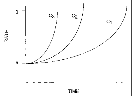
predetermined change in feed rate of each of the raw materials is made with
reference to
the rate of change of the transition rate-limiting operation. It is not
essential that the rate
3o of change be proportional to and timed with the rate that this rate-
limiting operation is
changed. Indeed, it is contemplated that the feed rates of some raw materials
may change
independent of the rate of change of the rate-limiting operation, but such
change will be
-18-
CA 02511936 2005-O1-25
WO 2004/054013 PCT/US2003/023759
reflected in the predetermined changes in rates. For example, when a steam
reformer is
used and the hydrogen production rate is to be increased, the rate that the
fuel and
oxygen-containing gas are fed to a burner for heating the reformer, are
typically changed
as quickly as possible, regardless of the rate that the rate-limiting
operation will change.
[0072] Sometimes a feed rate change during a transition will be effected to
compensate for a slower transition rate operation. By way of example, during
an increase
in hydrogen production rate, often the concentration of carbon monoxide
temporarily
increases. Hence in an aspect of this invention, the feed rate of the oxygen-
containing
raw material to the preferential oxidation reactor is at a level above
expected at steady
state in order to increase the amount of carbon monoxide oxidized. Similarly,
where a
process stream is used to cool the effluent from the reformer, an ancillary
heat transfer
means such as water injection into the effluent may be used and the rate of
water
injection controlled in accordance with a predetermined routine to compensate
during the
transition to the new hydrogen production rate.
[0073] Also in another aspect of the invention, certain feed rates of raw
materials are
maintained in predetermined ratios varying with the hydrogen production rates
during the
transition. In illustration, where the hydrogen generator uses an autothermal
reformer,
the fuel to oxygen-containing raw material ratio to the reformer may proceed
in
accordance with the algorithm
R = (k*b*F)/(1+bF)
wherein R is the fuel ratio defined as F/(F+A), F is the molar fuel flow, A is
the molar
oxygen-containing gas flow, and k and b are empirical constants. The same
algorithm
can set forth the predetermined flows of these raw materials at steady state
conditions at
various hydrogen production rates. Similarly, if water is injected into the
feed to the
autothermal reactor, the algorithm can be further refined to reflect the heat
required for
vaporization and sensible heating of the water.
[0074] The transition rate-limiting operation will be dependent upon the type
and
configuration of the hydrogen generator, and the transition rate-limiting
operation may be
different when the hydrogen production rate is increased than when the
hydrogen
production rate is decreased. In some instances, the transition rate-limiting
operation
may be different at one hydrogen production rate than at another rate.
-19-
CA 02511936 2005-O1-25
WO 2004/054013 PCT/US2003/023759
[0075] In the aspects of this invention where ratios of at least one
externally provided
raw material to fuel are changed during a transition period, the effect of
transition rate-
limiting conditions can be attenuated and desirable hydrogen product quality
maintained.
A particularly important benefit of this aspect of the invention pertains to
the efficacy of
the carbon monoxide reduction through a preferential or selective oxidation.
The
preferential oxidation reaction has the purpose of oxidizing the carbon
monoxide to
produce carbon dioxide, while a small fraction of the product hydrogen is
oxidized to
produce water. The low carbon monoxide levels that are desired for use with
PEM fuel
cells are readily achieved with the prior art processes when operating under
steady state
1o operating conditions. However, application of PEM fuel cells to residential
power
generation, or other applications that provide for intermittent operation,
requires the
provision of a fuel processor that can maintain low carbon monoxide levels
under
transient operating conditions. In particular, it has been found that periods
of high carbon
monoxide concentration can occur, generally during periods of increase in
throughput of
fuel (turn-up).
[0076] Depending upon such factors as reformate flow rate, steam to carbon
oxides
ratio, and the nature of the shift catalyst and the shift temperature, the
carbon monoxide
content of the gas exiting the shift reactor can be as low as 0.2 mol-% (dry
basis). Hence,
shift reactor effluent comprises a bulk mixture of hydrogen, nitrogen, carbon
dioxide,
2o water, carbon monoxide, and residual hydrocarbon.
[0077] The shift reaction is typically not enough to sufficiently reduce the
carbon
monoxide content of the reformate to the necessary level - i.e. below about
100 parts per
million volume (ppmv) and preferably below 10 ppmv. Therefore, it is necessary
to
further remove carbon monoxide from the hydrogen-rich reformate stream exiting
the
shift reactor, prior to supplying it to the fuel cell. It is known to further
reduce the carbon
monoxide content of hydrogen-rich reformate exiting a shift reactor by a so-
called
preferential oxidation reaction effected in a suitable preferential oxidation
reactor. A
preferential oxidation reactor usually comprises a catalyst bed, which
promotes the
preferential oxidation of carbon monoxide to carbon dioxide by air in the
presence of the
diatomic hydrogen, but without oxidizing substantial quantities of the
hydrogen itself.
Desirably, the oxygen required for the preferential oxidation reaction will be
no more
than about two to four times the stoichiometric amount required to react the
carbon
-20-
CA 02511936 2005-O1-25
WO 2004/054013 PCT/US2003/023759
monoxide in the reformate. If the amount of oxygen exceeds about two to four
times the
stoichiometric amount needed, excessive consumption of hydrogen results. On
the other
hand, if the amount of oxygen is substantially less than about two to four
times the
stoichiometric amount needed, insufficient carbon monoxide oxidation will
occur.
[0078] Preferential oxidation reactors may be either (1) adiabatic (i.e. where
the
temperature of the reformate (syngas) and the catalyst are allowed to rise
during
oxidation of the carbon monoxide), or (2) approximately isothermal (i.e. where
the
temperature of the reformate (syngas) and the catalyst are maintained
substantially
constant by heat removal from the reactor during oxidation of the carbon
monoxide). The
adiabatic preferential oxidation process may be effected via one or more
stages with
inter-stage cooling, which progressively reduce the carbon monoxide content.
Temperature control is important, because if the temperature rises too much,
methanation, hydrogen oxidation, or a reverse shift reaction can occur. This
reverse shift
reaction produces more of the undesirable carbon monoxide, while methanation
and
excessive hydrogen oxidation negatively impact system efficiencies and can
lead to large
temperature excursions and reactor instability.
[0079] The processes that have been previously developed have provided
satisfactory
results in reduction of the carbon monoxide level below the desired level when
operating
in a steady state mode. However, it is also necessary to maintain this low
level of carbon
monoxide concentration at all times during operation of the fuel processor in
order to
avoid poisoning of the PEM catalyst. In particular, previous to the present
invention,
considerable difficulty has been found with a rise in carbon monoxide levels
during turn-
up of the fuel processor. During rapid turn up, this proves to be even more of
a problem.
One reason for the difficulty in maintaining a low level of carbon monoxide is
that the
water gas shift reactor takes time to reach the appropriate operating
temperature, and
there is generally a time lag associated with steam production in the system.
[0080] In one embodiment, the fuel and steam are passed to a convection heated
pre-
reforming zone at a pre-reforming temperature to produce a pre-reforming
effluent. The
pre-reforming effluent and a first air stream are passed to a partial
oxidation zone in a
reaction chamber to produce a partial oxidation effluent. A controlled ratio
of water to
fuel is added into the fuel and steam. The partial oxidation effluent is
passed to a
reforming zone disposed in the reaction chamber to produce a reforming
effluent
-21 -
CA 02511936 2005-O1-25
WO 2004/054013 PCT/US2003/023759
comprising predominantly hydrogen, nitrogen, carbon dioxide and carbon
monoxide. The
reforming effluent is passed to a carbon monoxide reduction zone to produce a
hydrogen
product. The carbon monoxide reduction zone comprises a water gas shift zone
and at
least one preferential oxidation reactor. A controlled ratio of air to fuel is
added to the
hydrogen product prior to its entrance into the preferential oxidization
reactor. The
hydrogen product is passed to a fuel cell zone to produce electric power.
[0081] In another embodiment of this aspect of the invention, the water to
fuel ratio
and free oxygen to fuel ratio are adjusted in accordance with a predetermined
algorithm.
Water is added to the fuel prior to said fuel entering the reformer, and free
oxygen (air) is
added to said at least one preferential oxidation reactor in accordance with
an algorithm.
In one possibility, the algorithm may be used in conjunction with determining
whether
the hydrogen production rate is increasing or decreasing. In such an instance,
the
algorithm comprises determining a target hydrocarbon fuel flow (B) and a
current
hydrocarbon fuel flow (A), then determining a present difference (D) _ (B)-
(A), and then
comparing said difference (D) with a predetermined value to determine whether
the
hydrogen generator is turning up production of hydrogen, turning down
production of
hydrogen or operating at a steady state mode. A higher ratio of water to fuel
and free
oxygen to fuel is added when the hydrogen generator is turning up production
for a preset
period of time than when the hydrogen generator is operating at a steady state
mode. A
lower ratio of water to fuel and free oxygen to fuel is added when the
hydrogen generator
is in a turning down of production.
[0082] In another embodiment of this aspect of the invention, the hydrogen
produced
is used in a fuel cell system for electric power generation. The process
comprises a series
of integrated steps. The fuel is passed to a preparation module to produce a
conditioned
feedstock. The conditioned feedstock is passed to a pre-reforming zone
containing a pre-
reforming catalyst. The pre-reforming zone is in intimate thermal contact with
a first heat
exchange zone having a steady-state temperature profile to produce a pre-
reforming
effluent stream comprising hydrogen, nitrogen, carbon monoxide, carbon dioxide
and
water. Additional water in amounts calculated in accordance with the algorithm
used in
the practice of this aspect of the invention is injected into the pre-
reforming effluent
stream. The pre-reforming effluent stream at effective partial oxidation
conditions is
passed to a partial oxidation zone containing a partial oxidation catalyst. In
the partial
-22-
CA 02511936 2005-O1-25
WO 2004/054013 PCT/US2003/023759
oxidation zone the pre-reforming effluent is contacted with a first free
oxygen (air)
stream to produce a partial oxidation effluent stream. The partial oxidation
effluent
stream at effective reforming conditions is passed to a reforming zone. The
reforming
zone contains a reforming catalyst to produce a reforming effluent stream. The
reforming
effluent stream, or reformate, is withdrawn from the reforming zone at a
reforming exit
temperature. The reformate and a first water stream are passed to a water gas
shift
reaction zone containing at least one water gas shift catalyst zone. The water
gas shift
reaction zone is in intimate thermal contact with a second heat transfer zone
having a
steady-state temperature profile to cool the water gas shift reaction zone by
indirect heat
1o transfer to effective water gas shift conditions to produce a hydrogen
product stream
comprising hydrogen, nitrogen, carbon monoxide, carbon dioxide and water. The
hydrogen product stream is passed to an anode side of a fuel cell zone. The
fuel cell zone
has a cathode side on which an oxygen containing stream is contacted to
produce electric
power and an anode waste gas comprising hydrogen is withdrawn from the anode
side.
The anode waste gas is returned to a burner zone wherein the anode waste gas
is
contacted with a sufficient amount of a second air stream to combust the anode
waste gas
to produce a flue gas stream at a flue gas temperature. The flue gas stream is
passed to
the first heat exchange zone to heat the pre-reforming zone to the effective
pre-reforming
conditions.
[0083] One embodiment of this aspect of the invention is the algorithm for
control of
the ratio of the free oxygen for preferential oxidation (air):fuel ratio and
the water
injection:fuel ratio. In general, these ratios are highest when the throughput
of fuel is
increasing, less during steady state operation and even lower during a turn-
down of the
operation. As stated above, in determining the appropriate ratio to employ, a
flow target
is determined for the particular apparatus and then the present feed flow is
measured. The
difference in these two numbers is determined. When the number is greater than
a
predetermined value, then a greater volume of air is added to the preferential
oxidation
reactors and a greater amount of water is injected into the feed line. When
the flow target
is reached, a timer is initiated (i.e., the.start of the transition period)
and the free
3o oxygen:fuel and water:fuel ratios are maintained at their respective
predetermined values
until the timer expires (end of the transition period) or until another flow
target is
requested. When the timer expires, the respective ratios are set to their
steady state
- 23 -
CA 02511936 2005-O1-25
WO 2004/054013 PCT/US2003/023759
values. These ratios during the transition period may be set at one or more
steps or may
be continuously varied during the transition period.
[0084] In some aspects, the free oxygen:fuel and the water injection:fuel
ratios
become twice as high during turn-up as during turn-down. The steady state
ratio is about
25% higher than the lowest turn-down ratios. All ratios are calculated as
molar ratios.
[0085] The following Table 1 illustrates sample ratios for the free oxygen
(air):fuel
and water:fuel for natural gas fuel. These molar ratios may be determined by
experimentation. These ratios are specific to natural gas feed and would be
higher for
heavier fuels, such as LPG.
to Table 1
Turn-up Ratio Turn-down RatioSteady State
of Ratio
Air:Feed and of Air:Feed of Air:Feed
and and
Water:Feed Water:Feed Water:Feed
Air:Feed for
each
preferential 0.14 0.07 0.10
oxidation sta
a
Water:Feed 1.00 0.20 0.40
DETAILED DESCRIPTION OF THE DRAWINGS
[0086] The invention will be further described with reference to the drawings
which
description is not intended to be in limitation thereof.
[0087] Referring to Figure 1, which illustrates a simplified schematic of a
hydrogen
fuel processor (hydrogen generator) for use with a fuel cell, a hydrocarbon
(e.g., natural
gas) and steam feed in a line 2 is passed to a preheat exchanger 4. Water feed
in a line 3
for injection of a desired flow of water enters the line 2, prior to entrance
into the preheat
exchanger, which may incorporate a pre-reforming zone. A pre-reforming
effluent stream
is withdrawn from the preheat exchanger 4 in a line 6, with addition of a
measured
2o quantity of a first air stream 5 to the line 6 which leads to an
autothermal reforming
(ATR) reactor 7. In the ATR reactor 7, at least a portion of the pre-reforming
effluent
stream is converted to produce an ATR reactor effluent stream comprising
hydrogen,
nitrogen, carbon monoxide, carbon dioxide and water. The ATR reactor effluent
stream
is withdrawn from the ATR reactor 7 and passed through a line 8 to a water gas
shift
-24-
CA 02511936 2005-O1-25
WO 2004/054013 PCT/US2003/023759
reactor 9. The water gas shift reactor 9 contains at least one water gas shift
catalyst zone
and provides for the conversion of carbon monoxide to carbon dioxide to
produce a
hydrogen product stream having a low level of carbon monoxide. The hydrogen
product
stream is withdrawn from the water gas shift reactor 9 in a line 10. If the
fuel cell is of a
type that is sensitive to carbon monoxide, the concentration of carbon
monoxide needs to
be further reduced.
[0088] Selective oxidation techniques (also known as preferential oxidation)
are
preferred for the further reduction in level of carbon monoxide. For example,
reduction
of the carbon monoxide concentration to a level of less than 10 ppmv is
required for
1o PEM-type fuel cells, while phosphoric acid fuel cells have a higher carbon
monoxide
tolerance. As shown in Figure 1, the hydrogen product stream passes through
the line 10
into at least one preferential oxidation reactor 12. In some embodiments of
the invention,
a second preferential oxidation reactor, 14, as illustrated herein, is
provided with the
hydrogen product stream passing through a line 16. A measured flow of air is
added to
15 the hydrogen product stream through a line 11 and through a line 13 when
the second
preferential oxidation reactor 14 is present. In general, the volume of air is
split equally
between the two preferential oxidation reactors.
[0089] The hydrogen product stream leaves the preferential oxidation reactor
12 or
preferential oxidation reactor 14 when two units are used and is passed to an
anode side
20 of a fuel cell through a line 15, while an oxygen containing stream such as
air is passed to
a cathode side of the fuel cell and an anode waste stream which is now
depleted in
hydrogen relative to the hydrogen product stream is withdrawn from the fuel
cell.
[0090] Figure 2 represents a system for conversion of a hydrocarbon feedstock
such
as a natural gas stream in a line 30 to electric power using a fuel cell 97.
Referring to
25 Figure 2, a natural gas stream in the line 30 is passed to a treater 90
comprising a
desulfurization zone or zone for removal of other impurities. The
desulfurization zone
contains a sorbent for the removal of impurities such as sulfur compounds
including
hydrogen sulfide and mercaptans. The desulfurization sorbent is selected from
the group
consisting of zeolites, activated carbon, activated alumina, zinc oxide,
mixtures thereof
30 or other materials known to those skilled in the art as useful in removal
of impurities
from natural gas. A processed natural gas stream is removed from the treater
zone in a
line 34. Water can be added to the stream through a line 32, as necessary. A
natural gas
- 25 -
CA 02511936 2005-O1-25
WO 2004/054013 PCT/US2003/023759
compressor 40 is shown for maintaining the flow of gas feed to the system. The
treated
gas feed goes through line 34. Steam from the boiler 75 passes through a steam
line 74 to
be combined with the treated gas feed in the line 34. An additional amount of
water can
be injected into the line 34. The amount of water injected into the system is
calculated in
accordance with the present invention and is dependent upon the stage of
operation of the
fuel processor. The feed in the line 34 that now contains a mixture of treated
gas feed,
steam and injected water now proceeds to a vaporizer 50 to produce steam from
the
injected water. The vaporizer 50 comprises a plate-type heat exchanger.
[0091] From the vaporizer 50, the gas feed/steam mixture passes through a line
48 to
l0 a pre-reformer 60. The pre-reformer zone contains a pre-reforming catalyst
selected from
the group consisting of nickel on alumina and the like. The pre-reformer 60 is
in intimate
thermal contact with a heat exchange zone which supplies heat by indirect heat
exchange
in the convection temperature range to heat the pre-reformer 60. A pre-
reforming effluent
stream is withdrawn from the pre-reformer 60 in a line 62. A first air stream
37 passes
through a blower 38 and is added to an anode waste gas stream 98 and then is
heated in a
burner 44. In other embodiments of the present invention, the anode waste gas
stream 98
may be replaced with a portion of the gas that passes through the treater 90.
This
produces a heated flue gas stream 46 that provides the heat to the heat
exchange zone in
intimate contact with the pre-reformer 60.
[0092] From the pre-reformer 60, the pre-reforming effluent stream passes
through
the line 62 to a combined partial oxidation reactor/reformer, also known as an
autothermal reformer (ATR) reactor 70. The pre-reforming effluent stream is
passed to a
partial oxidation zone at effective partial oxidation conditions including a
partial
oxidation temperature between about 550° and about 900°C
(932° and 1652°F) and a
partial oxidation pressure between about 100 to about 350 kPa (15 to about 50
psi).
Either simultaneously with the introduction of the pre-reforming effluent or
as a partial
oxidation feed admixture combined with the pre-reforming effluent stream, an
air stream
in a line 41a is introduced to the ATR reactor 70. A blower 39 is used to
create the air
stream in the line 41a. The partial oxidation zone within the ATR reactor
contains a
3o partial oxidation catalyst. In the partial oxidation zone, at least a
portion of the pre-
reforming effluent stream is converted to produce a partial oxidation effluent
stream
comprising hydrogen, nitrogen, carbon monoxide, carbon dioxide, water and
unreacted
- 26 -
CA 02511936 2005-O1-25
WO 2004/054013 PCT/US2003/023759
hydrocarbon. The partial oxidation effluent is passed to a reforming zone
within the ATR
reactor 70. The reforming zone contains a reforming catalyst. In the reforming
zone, the
partial oxidation effluent stream undergoes a further conversion to produce a
reforming
effluent stream comprising hydrogen, nitrogen, carbon monoxide, carbon dioxide
and
water. The partial oxidation zone and the main reforming zone are combined
into a single
combined reaction zone comprising the ATR reactor 70.
[0093] The reforming effluent stream now goes through a line 64 to a water gas
shift
reactor 80 which contains at least one water gas shift catalyst zone and
provides for the
reduction in concentration of carbon monoxide to produce a hydrogen product
stream.
The hydrogen product stream is withdrawn from the water gas shift reactor 80
to then be
treated in one or more preferential oxidation reactors 82, 84. The water gas
shift reaction
is a mildly exothermic reversible reaction and must be cooled to maintain a
suitable
reaction temperature. The water gas shift reactor 80 is cooled by indirect
heat exchange
with a second heat exchange zone, shown herein as the boiler 75. As practiced
in the
preferred embodiment of the present invention, the boiler 75 produces the
steam that
goes through the line 74 and enters the line 34 as described above to be
admixed with the
hydrocarbon feed and the additional water injected into the system.
[0094] As shown in Figure 2, the hydrogen product stream passes through a line
87
to a knock-out pot 86 where the hydrogen product stream is cooled by room
temperature
2o air or another cooling means in order to condense and remove water. The
water may be
recycled to a water reservoir 88 and returned to the boiler 75 or the water
may be
discarded. The hydrogen product stream is then sent to the line 87 to a
preferential
oxidation reactor zone shown herein as the preferential oxidation reactors 82,
84. A
second air stream 41b is added to the preferential oxidation reactors 82, 84.
Equal
volumes of air may be sent to each preferential oxidation reactor or different
amounts as
calculated appropriate for maximum reduction of carbon monoxide level. The
amount of
air added to the preferential oxidation reactors 82, 84 is calculated in
accordance with the
present invention. The preferential oxidation reactors 82, 84 may be
positioned in an
annular arrangement in order to maximize surface area in contact with the
water within
3o the boiler 75. The preferential oxidation reactors 82, 84 contain a
preferential oxidation
catalyst to convert virtually all of the remaining carbon monoxide to carbon
dioxide.
-27-
CA 02511936 2005-O1-25
WO 2004/054013 PCT/US2003/023759
[0095] After being treated in the preferential oxidation reactor, the final
hydrogen
product stream passes to an anode side 93 of the fuel cell 97 along with an
oxygen
containing stream (air, not shown) that enters a cathode side 95 of the fuel
cell 97
wherein the hydrogen and oxygen react to produce electric current.
[0096] In Figure 3 is illustrated an algorithm for control of the preferential
oxidation
reactor air:hydrocarbon feed ratio and the water injection:hydrocarbon feed
ratio. In a
block 101 is shown the hydrocarbon feed flow target set point B which depends
upon the
hydrogen output desired from the fuel cell or other uses of the hydrogen
product. In a
block 102 is the current set point for hydrocarbon feed flow A. In a block 103
is the
equation D=B-A. In a decision block 104, the difference D is compared with a
pre-
determined threshold value. If D is greater than zero and D is greater than
the threshold
value (True), then the fuel processor is considered in a turn-up mode and the
algorithm
passes to block 105. In block 105, the air:fuel or water:fuel ratio is set to
an appropriate
value for turn-up (see Table 1). Also in block 105, a timer is reset to zero.
Control
execution then passes to block 106, where the respective air or water flow set
point is
output to the controller. Referring again to block 104, if D is less than the
threshold value
(False), then the algorithm passes to block 108. In the decision block 108, if
D is less
than zero and the absolute value of D is greater than the threshold value
(True), then the
fuel processor is considered in a turn-down mode and the algorithm passes to
block 109.
In block 109, the air:fuel or water:fuel ratio is set to an appropriate value
for turn-down
(see Table 1). Also in block 109, a timer is reset to zero. Control execution
then passes to
block 110, where the respective air or water flow set point is output to the
controller.
Referring again to block 108, if D is greater than the threshold value
(False), then the
algorithm passes to block 112. In block 112, a timer is initiated and the
algorithm passes
to block 113. In the decision block 113, if the timer has not expired (True),
then the
algorithm passes to block 114. In block 114, the air:fuel or water:fuel ratio
is maintained
at the respective turn-up or turn-down value. When the timer expires in block
113
(False), the algorithm passes to block 115. In block 115, the air:fuel or
water:fuel ratio is
reset to the respective value for steady state operation (see Table 1).
[0097] The control algorithm in Figure 3 executes in a continuous fashion,
thereby
providing an appropriate air:fuel or water:fuel ratio for the particular
operating mode of
the fuel processor (turn-up, turn-down, or steady state). The timer function
allows the
-28-
CA 02511936 2005-O1-25
WO 2004/054013 PCT/US2003/023759
respective ratios to be maintained at the tum-up or turn-down values for a
period of time
after the turn-up or turn-down has been completed. It has been found that this
delay in
resetting the respective ratios to their steady state values after completing
a ramp-up is
essential for maintaining a low carbon monoxide concentration.
[0098] In Figure 4 is shown the effect of the use of the algorithms of the
present
invention in control of the carbon monoxide level through variations in fuel
flow. As
shown on the chart, feed flow in percent of design capacity is varied from 50
to 110%
with concentration of carbon monoxide shown for four test runs. In Test 1, the
control
test, where the preferential oxidation reactor air to natural gas fuel ratio
was held
constant and where there was no water injection, there was a very significant
peak shown
of carbon monoxide level to above 2500 ppmv. In Test 2, a constant ratio of
water to
feed and a constant ratio of air to feed was used and there was somewhat less
carbon
monoxide produced as a result of the water injection, but the level was still
much more
than acceptable. In Tests 3 and 4, the preferential oxidation air was varied
in accordance
with the algorithm of the present invention as well as the addition of water.
The carbon
monoxide spike was greatly reduced in Tests 3 and 4.
[0099] A series of tests was performed using an apparatus, essentially as
shown in
Figure 2, to test the effectiveness of the algorithm for water injection and
preferential
oxidation air. The feed flow of natural gas was increased from 50% of design
to 100% of
2o design level in 30 minutes. The feed flow was then held constant at 100%
for 30 minutes
before ramping down to 70% in 10 minutes. After holding at 70% for 20 minutes,
the
feed flow was increased to 110% over a 20-minute interval. The feed was held
at 110%
for 20 minutes prior to finally ramping down to 50% in 22 minutes. Ramping of
feed
flow was performed automatically with an algorithm that keeps the percentage
change
constant to provide an exponential flow vs. time curve.
[00100] Prior to each test, the unit was operated at a 50% flow steady-state
condition.
Four tests were performed. Test 1 was performed with a constant preferential
oxidation
air:natural gas feed ratio and no water injection. Tests 2, 3 and 4 all
included water
injection at a constant water:feed ratio of 1Ø Test 2 used a constant
preferential
oxidation air:feed ratio, while Tests 3 and 4 included preferential oxidation
air at a ratio
to feed determined in accordance with the algorithm used in the present
invention. The
ratio of air:feed was higher on turn-up and reduced on turn-down.
-29-
CA 02511936 2005-O1-25
WO 2004/054013 PCT/US2003/023759
[00101] Carbon monoxide concentration in the product stream was continuously
monitored with an infrared detector and the results are shown in Figure 4.
There was a
large carbon monoxide spike in Test 1 during the initial turn-up of the feed,
peaking near
the end of the ramping up at 2800 ppmv. In Test 2, the addition of the water
injection
reduced the initial carbon monoxide spike significantly, but the maximum
remained high,
at 1900 ppmv. The combination of the water injection and the preferential
oxidation air
algorithm almost eliminated the initial spike of carbon monoxide - the peak
maxima
were 90 ppmv and 70 ppmv for Tests 3 and 4, respectively. In order to compare
results,
the peaks were integrated according to the formula I = J (Fuel Flow) x ycodt
where yco is
to the carbon monoxide concentration. The integral I is roughly proportional
to the amount
of carbon monoxide that would be deposited on the fuel-cell anode. Integrated
results,
normalized with respect to Test 1, are given in the following Table 2. All
data for yco >
20 ppmv were included in the integration.
Table 2
Test No. I
1 1.00
2 0.59
3 0.021
4 0.013
15 [00102] Figure 5 is an illustration of control algorithms implemented upon
an increase
in demand for hydrogen production and for a decrease in demand of hydrogen
production. Time T' is the beginning of the first transition period (I) and TZ
is the end of
the period. During this period, the hydrogen production increases, and as can
be seen,
the desired hydrogen production rate is achieved prior to the end of the
transition period
20 and before steady state at the new hydrogen production rate is achieved.
Similarly,
transition period II starts at time T3 and ends at T4, during which time the
rate of
hydrogen production is decreased. Again, the sought hydrogen production rate
is
achieved prior to the end of the period and steady state operation being
achieved. The
free oxygen to fuel and the water to fuel ratios vary over the transition
period to
25 accommodate inherent lags in the hydrogen generator to achieve steady state
conditions
at the new hydrogen production rate.
-30-
CA 02511936 2005-O1-25
WO 2004/054013 PCT/US2003/023759
[00103] Figure 6 is a schematic depiction of an integrated hydrogen
generator/fuel cell
system. The hydrogen generator is generally depicted by box 602 and the fuel
cell by
box 604. Sensor 606 determines the electric power demand and the hydrogen feed
rate to
the fuel cell to produce that amount of power. A hydrogen demand signal
generated by
sensor 606 is sent via line 608 to computer 610 having therein predetermined
feed rates
for the raw material to hydrogen generator 602 for its operational condition.
Signals are
generated by computer 610 for controlling the feed rate of each of the
externally-
provided raw materials. These control signals are transmitted to the
individual
controllers. For purposes of ease of reference, line 612 is to generally
indicate the lines
1o to each controller. The controllers are generally indicated by block 614.
Block 614
contains a controller for each of the raw material streams.
[00104] The number of raw material streams will depend upon the particular
design of
hydrogen generator. As depicted for illustration herein, Figure 6 shows seven
streams
(each of which are an externally-provided raw material stream) for a hydrogen
generator
15 using an autothermal reformer, a two stage water gas shift reactor and a
preferential
oxidation reactor as summarized by the following table.
Number Stream Destination
Identifier
616 F, Fuel to reformer
618 FZ Fuel to preheater
620 A, Oxygen-containing gas to reformer
622 AZ Oxygen-containing gas to preferential
oxidation reactor
624 W, Water to reformer
626 WZ Water for injection after reformer
628 W3 Water for injection between water gas
shift reactor stages
[00105] The supply to the controllers for fuel is via line 630, for oxygen-
containing
gas via line 632 and for water via line 634.
[00106] The hydrogen product from hydrogen generator 602 is passed via line
636 to
2o fuel cell 604 for conversion to electricity transmitted via line 638.
Although sensor 606
is shown as being in communication with line 638, it is often the case that
the sensor is
-31 -
CA 02511936 2005-O1-25
WO 2004/054013 PCT/US2003/023759
internal to the fuel cell itself. The fuel cell also exhausts an anode waste
gas and a
cathode waste gas, both of which are shown as being passed to hydrogen
generator 602
via lines 640 and 642 respectively. These streams may be used for heat
exchange as well
as for combustion to generate heat, e.g., for preheating the fuel. A flue gas
exhaust from
hydrogen generator exits via line 644.
[00107] For a more detailed illustration of one way in which raw materials may
be
used in a hydrogen generator, reference is made to Figure 7. In this figure,
the use of a
steam reformer 202 is depicted. A flow of fuel, F1, is controlled at a
predetermined rate
and passed via line 204 to mixer/preheater 206. A flow of water, W1, is
controlled at a
predetermined rate and passed via line 208 to mixer/preheater 206. Not shown
is the
source of the heat for mixer/preheater 206. The predetermined amounts of fuel
and water
are selected for the rate of hydrogen generation sought.
[00108] An admixture of the fuel and now steam is passed via line 210 to heat
exchanger 212 where through indirect heat exchange it is heated by the
reformate from
reformer 202 and cools the reformate. The further heated admixture is passed
via line
214 to reformer 202. Since steam reforming is endothermic and occurs at high
temperatures, combustor 216 is provided in indirect heat exchange with
reformer 202.
As shown, a flow of fuel, F2, is controlled at a predetermined rate and passed
via line 218
to combustor 216 and a flow of air, A1, is controlled at a predetermined rate
and passed
via'line 220 to combustor 216. The Fz flow rate is in an amount predetermined
to
maintain the reformer at a desired temperature for the endothermic steam
reforming.
Combustion effluent exits combustor 216 via line 222 and can be used for heat
integration, for instance as the source of heat for mixer/preheater 206, and
then exhausted
from the hydrogen generator.
[00109] Reformate exits reformer 202 via line 224 and is passed through heat
exchanger 212 and then to heat exchanger 226. Heat exchanger 226 uses the
addition of
water into the reformate for direct heat exchange. Water is passed via line
228 at a
predetermined flow rate, W2, to further cool the reformate to a desired
temperature for
further processing. The cooled reformate is passed via line 230 to the carbon
monoxide
conversion operation.
-32-
CA 02511936 2005-O1-25
WO 2004/054013 PCT/US2003/023759
[00110] One sequence of operation during a change in hydrogen production rates
is as
follows. To effect a rapid increase in hydrogen production, F~ and W 1 are
increased at
predetermined ramp-up rates, but in the same molar ratio. FZ and A, also are
increased at
predetermined rates because more heat is needed to reform the greater flow of
fuel, F~ to
the reformer. However, due to the time lag associated with indirect heat
transfer from the
burner flue gas to the reformer, F2 and A, are increased more rapidly than Fl
and W 1 and
more rapidly than if the transition to the higher hydrogen production rate
were slower.
This incremental excess heat input is used to compensate for the slow thermal
response
of the heat exchanger during the rapid turn-up and allows the reformer outlet
temperature'
1o to remain essentially constant. If necessary to accommodate the speed of
the turn-up, FZ
and A, may be greater than that required at steady state operation at the new
hydrogen
production rate. If so, FZ and A1 are reduced as steady state operation is
approached to
the appropriate rates for steady state operation at the new hydrogen
production rate.
[00111] Also during the period of ramp up, the lag in thermal response in heat
is exchanger 212 will be accommodated by temporarily increasing the flow of
water to heat
exchanger 228 via line 226 (WZ). As the unit approaches steady state operation
at the
new hydrogen production rate, W2, will be lower than before the transition
commenced.
It is readily apparent that similar sequencing of changes in flow rates can be
done to
achieve a rapid reduction in hydrogen production rate.
20 [00112] Figure 8 depicts an autothermal reformer and water gas shift
section of a
hydrogen generator. Autothemal reformer 302 uses a fuel, oxygen-containing gas
and
water feed. As shown, fuel passing through line 304 at a predetermined,
controlled flow
rate F,, is admixed with steam via line 344. Line 344 usually contains low
temperature
steam recovered from the hydrogen generator, preferably from a preferential
oxidation
25 reactor. See the discussion of Figure 9 and line 412.
[00113] This fuel/steam admixture is passed via line 304 to heat exchanger
306. The
heated fuel is passed via line 308 to mixer 310. Water at a predetermined,
controlled
rate, W1, via line 318 and an oxygen-containing gas at predetermined flow
rate, A~, from
line 312 are passed to heat exchanger 316 to provide a steam and water-
containing
30 mixture. Heat exchanger 316 is heated by combusting anode waste gas via
line 320 and
cathode waste gas via line 322. As shown, a predetermined, controlled oxygen-
containing gas flow, A3, is also provided via line 324 for use in the
combustion in the
- 33 -
CA 02511936 2005-O1-25
WO 2004/054013 PCT/US2003/023759
heat exchanger. The heated steam and oxygen-containing gas generated in heat
exchanger 316 is passed via line 314 to mixer 310 for combination with the
heated fuel
and steam admixture from line 308.
[00114] The fuel, steam and oxygen-containing gas mixture is passed to
reformer 302
via line 326. The reformate is passed from reformer 302 via line 328 for
indirect heat
exchange with the fuel in heat exchanger 306 and then to heat exchanger 330
which uses
water injection into the reformate for further cooling. The water flow, WZ, is
at a
predetermined, controlled rate and is passed to heat exchanger 330 via line
332.
[00115] The cooled reformate is then passed to a two stage water gas shift
reactor 334
1o and 336 having heat exchanger 338 between shift stages. Heat exchanger 338
also uses
the injection of water for cooling the gases. The water flow, W3, is at a
predetermined,
controlled rate and enters the heat exchanger via line 340. The reformate,
having been
subjected to the water gas shift reaction, is passed via line 342 for further
processing,
e.g., in a preferential oxidation reactor.
[00116] Figure 9 depicts a preferential oxidation section of a hydrogen
generator. The
preferential oxidation reactor 402 receives hydrogen-containing gas via line
404. The
hydrogen-containing gas is generally obtained from a water gas shift reaction,
which is
usually at a higher temperature than desired for the preferential oxidation.
If so, some
cooling of the hydrogen-containing gas may be effected. Oxygen-containing gas
flow,
A2, is provided via line 406 at a predetermined rate. A hydrogen product
having a
reduced concentration of carbon monoxide exits via line 408. As the
preferential
oxidation reaction is exothermic, a cooling stream is provided via line 410.
Typically,
the cooling stream is water and low pressure steam is generated as the heat of
reaction is
removed. In this manner, the preferential oxidation can be operated at a
desirable
temperature. The steam is recovered via line 412. The hydrogen-containing
stream in
line 408 is often cooled with condensed water being removed, prior to entry
into the
anode side of a fuel cell.
[00117] It is typical that when the hydrogen production rate is increased,
during the
transition the concentration of carbon monoxide in the gases passing to the
preferential
oxidation reactor increases. Advantageously, the oxygen-containing gas flow
rate via
line 406 is increased beyond that predetermined for steady state operation at
the new
-34-
CA 02511936 2005-O1-25
WO 2004/054013 PCT/US2003/023759
hydrogen production rate to maintain the carbon monoxide concentration in the
hydrogen
product exiting via line 408 at an acceptable level.
[00118] Figure 10 is an illustration of the responses of three conditions in a
hydrogen
generator to a change from hydrogen production rate A to rate B. Condition C1
has a
slow transient response, e.g., it may be the steam production rate from an
indirect heat
exchange, whereas condition CZ is more rapid, e.g., a catalyst temperature,
and condition
C3 is even more rapid, e.g., fuel to oxygen-containing gas ratio in the feed
to the
reformer. C, would, amongst the three conditions, be the transition rate-
limiting
operation. Assuming for purposes of illustration that the changes in C~ to CZ
to C3 are to
occur simultaneously, in accordance with the present invention, the rate of
change of CZ
and C3 would be controlled in a predetermined manner to coincide with the
change in C1.
This control would be through adjusting the flows of the externally-provided
raw
materials at a predetermined change rate to the set of predetermined
conditions for the
new hydrogen production rate.
-35-