Note : Les descriptions sont présentées dans la langue officielle dans laquelle elles ont été soumises.
CA 02512772 2005-06-23
WO 2004/064681 PCT/US2004/001427
URETERAL STENT CONFIGURED FOR IMPROVED
PATIENT COMFORT AND AFTERCARE
Field of the Invention
[0001] The invention relates generally to stems; more particularly, the
invention relates to
ureteral stems.
Background of the Invention
[0002] A ureter is a tubular passageway in the body that conveys urine from a
kidney to a
bladder. Blockages of the ureter may cause hydronephrosis, a condition
characterized by
damming of urine in the kidneys, resulting in swelling and inflammation of the
upper urinary
tract and the kidneys. This may lead to kidney dysfunction and eventual
necrosis. Ureteral
bloclcages, also called ureteral strictures, may be congenital or acquired.
Acquired blockages
to may be caused by disease, injury, lcidney stones, and tumors. Both
congenital and acquired
blockages generally require medical intervention, for example, the use of
ureteral stems.
[0003] Ureteral stents are used to facilitate urinary drainage from the kidney
to the bladder in
patients having a ureteral obstruction or injury, or to protect the integrity
of the ureter in a variety
of surgical manipulations. Ureteral stems are typically about 30-cm long,
hollow catheter-like
devices composed of a polymer and placed within the ureter with the proximal
end residing in
the kidney and the distal end in the bladder. Ureteral stems function by
channeling the flow of
urine from the kidney to the bladder. One or both ends of a ureteral stmt may
be coiled in a
pigtail shape to prevent the upward and/or downward migration of the stmt due
to patient
movement. The ureter may stretch up to 5 cm in either direction during a
patient's normal
2o bodily movements, such as movement during breathing. If the stmt is not
sufficiently anchored,
this may result in stmt migration and displacement. Also, a stmt may cause
tissue irritation due
to the relative movement between the stmt and the ureter during natural
stretching of the ureter,
even when the stmt is properly anchored. A typical semi-rigid, anchored stmt
is unable to
adjust for the natural extension and contraction of the ureter during bodily
movements, resulting
in pressure and irritation of the ureter and surrounding tissue.
[0004] Regions of tissue most vulnerable to stmt-induced irritation include
the kidney, the
renal pelvis, the sensitive bladder tissue in the trigonal region, and the
tissue of the ureteral
CA 02512772 2005-06-23
WO 2004/064681 PCT/US2004/001427
vesical junction leading into the bladder. Irritation may be caused by the
static or dynamic
contact of the semi-rigid stmt with sensitive tissues of the body, such as the
kidney and the renal
pelvis. Chronic trigonal tissue irritation may result from contact of tissue
by the bladder-
anchoring features of the stmt, for example, pigtails at the stmt ends.
Irritation problems are of
concern regardless of the duration of use of the stem; however, irritation is
of particular concern
where use of a stmt is required over a long period of time.
[0005] Another problem associated with ureteral stems is urine reflux and pain
during urine
voiding. On the initiation of voiding, the bladder wall muscles contract
causing the pressure
inside the bladder to increase. Because a typical ureteral stmt holds the
ureteral orifice open,
to increased bladder pressure during voiding is transmitted to the kidney
through the stmt, causing
urine reflux and flank pain.
Summary of the Invention
[0006] The invention provides a ureteral stmt configured to address a variety
of sources of
irritation associated with the use of conventional ureteral stems. These
irritations include, for
15 example, irritation in the trigonal region of the bladder due to semi-rigid
stmt contact with
bladder mucosa, ureteral vesical junction irritation caused by extension of
this region beyond a
typical relaxation conformation, pain in the lcidney and/or renal pelvis due
to the presence therein
of part of a semi-rigid stent, and flank pain associated with urine reflux
during voiding of the
bladder.
20 [0007] The invention features a stmt that addresses these sources of
irritation by including one
or more of the following features: a portion at the distal end having a non-
circular cross-section;
a proximal portion having a helical coil shape configured to allow anchoring
of the stmt below
the kidney and at or below the renal pelvis; and a portion having an irregular
coil shape to allow
self adjustment of the stmt with ureteral movement.
25 [0008] In one embodiment, the distal portion of the stmt includes a section
of hollow tube with
a non-circular (e.g., somewhat flattened) profile. The non-circular profile is
intended to more
closely follow the contour of the intramural tunnel and ureteral vesical
junction than does a
circular profile. Extension or widening of the cross-section of the ureteral
vesical junction due to
the presence of the stem is minimized. Thus, there is less irritation caused
by the stent at the
3o ureteral vesical junction. The non-circular-profile section of the stmt
also provides a more
flexible, less rigid distal end portion that eases pain and irritation, for
example, in the trigonal
region of the bladder.
CA 02512772 2005-06-23
WO 2004/064681 PCT/US2004/001427
[0009] The non-circular-profile section of the stmt also provides for the
reduction or
elimination of urine reflux from the bladder to the kidney during voiding,
thereby preventing the
associated flank pain. Pressure external to the stmt at the non-circular-
profile section of the
stmt collapses the stmt shut during voiding of the bladder and prevents reflux
of urine to the
kidney. After voiding, the stmt opens again upon resumption of a normal
bladder pressure. The
non-circular-profile section of the scent may be made even more flexible and
collapsible by the
use of a thinner wall thiclaiess in this section. In an embodiment, the distal
portion of the stmt is
anchored in the bladder by a pigtail-shaped end portion, at least part of
which has a non-circular
cross-section to allow reduced irritation in the bladder and in the urinary
vesical junction region.
1 o [0010] In another embodiment, the ureteral stmt has a proximal portion
configured to self
anchor inside an upper portion of the ureter, at or below the renal pelvis, to
minimize or
eliminate stmt irritation in the kidney and/or the sensitive renal pelvis
region. In one
embodiment, a substantially three-dimensional helical coil shape of
sufficiently large helix
diameter provides an anchor inside the upper portion of the ureter. By
anchoring the stmt below
the kidney, irritation is minimized in the sensitive renal pelvis region.
[0011] Another embodiment provides a stmt with a portion forming an irregular
helical coil
shape to enable the stmt to self adjust with patient movement, thereby
reducing irritation due to
normal stretching and conformational change of the ureter. The irregular
helical coil shape
provides a self adjusting reserve of stent length to allow for stmt
elongation, contraction, and
other conformation change caused by movement of the ureter. The irregular
helical coil shape
may also provide an additional source of support for the stmt within the
ureter. In one
embodiment, a stmt has an irregular helical coil shape along its length, as
well as a proximal end
portion having a regular helical shape for anchoring the stmt below the
kidney. The portion of
the stmt having an irregular helical coil shape may be configured with
sufficient helix diameter
and height of helix extension so that (1) the proximal portion of the stmt is
more stably anchored
below the lcidney, and (2) the stmt self adjusts by elongating and contracting
with patient \
movement. In one embodiment, the irregular helical coil shape has an
increasing height of helix
extension -- fewer turns per unit length -- toward the distal portion of the
stmt near the bladder.
The irregular nature of the helical coil shape in this embodiment better
follows the anatomy of
3o the ureter than would a regular helical coil shape, and provides reduced
stmt weight, reduced
pressure against ureteral tissue, and reduced irritation to the local tissue
without compromising
the self anchoring ability of the stmt. In an alternative embodiment, the stmt
has a portion
CA 02512772 2005-06-23
WO 2004/064681 PCT/US2004/001427
forming a substantially regular helical coil shape to enable the stmt to self
adjust with patient
movement.
Brief Description of the Drawings
[0012] The objects and features of the invention can be better understood with
reference to the
drawings described below, and the claims. The drawings are not necessarily to
scale, emphasis
instead generally being placed upon illustrating the principles of the
invention. In the drawings,
like numerals are used to indicate lilce parts throughout the various views.
[0013] Figure 1 depicts an embodiment of a ureteral stmt of the invention.
[0014] Figure 2, Figure 2-1, and Figure 2-2 depict the ureteral stmt of Figure
1, together with
1o insets illustrating cross-sections at two locations along the body of the
stmt.
[0015] Figure 3 depicts the ureteral stmt of Figures l and 2 as positioned in
a ureter with a
proximal portion anchored inside an upper portion of the ur eter, below the
kidney, and with a
distal portion anchored inside the bladder.
[0016] Figure 4 depicts a helical portion of the body of the stmt of Figures 1-
3 along with
15 geometric indicators.
Detailed Descri tp ion
[0017] The invention provides a ureteral stmt configured for improved patient
comfort and
aftercare. In one embodiment, the stmt has a distal portion with a somewhat
flattened, non-
circular cross-section, thereby providing a more flexible, less rigid, self
aligning lumen in the
2o sensitive trigonal region of the bladder. In another embodiment, the stmt
features a proximal
portion with a helical coil shape to allow self anchoring of the stmt below
the kidney, at or
below the renal pelvis. Furthermore, one embodiment includes a stmt with a
portion along its
length having an irregular coil shape to allow self adjustment of the stmt
with ureteral
movement. Other embodiments of the invention include stems with various
combinations of the
25 aforementioned features.
[0018] Additionally, the invention provides a method of self adjusting the
effective length of a
ureteral stmt to compensate for patient movement, thereby providing improved
patient comfort.
An embodiment of the method includes providing a ureteral stmt with a portion
of its length
having an irregular coil shape, anchoring the proximal pouion of the stent
inside the upper
3o portion of the ureter below the kidney, and allowing the stmt to self
adjust in response to patient
movement. Patient movement, such as movement during breathing, causes the
length of the
stmt to expand or contract in response to the natural movement of the ureter.
Anchoring the
stmt below the lcidney and at or below the renal pelvis provides increased
comfort and reduced
CA 02512772 2005-06-23
WO 2004/064681 PCT/US2004/001427
irritation to the kidney and/or the renal pelvis. The stmt used in this method
may have any
combination of the stmt features described herein.
[0019] LJreteral stems of the present invention are used, for example, to
facilitate urinary
drainage from the lcidney to the bladder in patients having ureteral
obstructions or injuries, or to
protect the integrity of the ureter in a variety of surgical manipulations. A
patient may undergo
either short-term or long-term ureteral stenting. Short term stenting
generally lasts up to a period
of a weeks, and long-term stenting may last for a period of months or years.
In addition to
facilitating urinary draining through obstructed ureters, stenting may be used
as an adjunct to
open surgical procedures of the urinary tract to provide a mold around which
healing can occur,
to or to divert the urinary flow away from areas of leakage. Other uses of
stems of the present
invention include, for example, maintaining the functionality of ureters
following balloon
dilation or incision of ureteral strictures, manipulating or preventing kidney
stone migration prior
to treatment, and malting ureters more easily identifiable during difficult
surgical procedures.
Additionally, ureteral stems of the present invention may be used in those
with active kidney
infection or with markedly diseased, intolerant bladders, such as bladders
damaged from
radiation therapy, or bladders invaded by adj acent neoplasm.
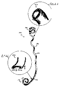
[0020] Figure 1 depicts an embodiment of a ureteral stmt 100 of the invention.
The stmt 100
of Figure 1 includes an elongated, substantially liollow body 101 having a
distal portion 102 with
a somewhat flattened, non-circular cross-section, a proximal portion 106 with
a helical coil shape
2o to allow self anchoring of the stmt below the kidney and at or below the
renal pelvis, and a
portion along the body of the stmt 104 having an irregular coil shape to allow
the stmt to self
adjust with ureteral movement. As used herein with regard to a ureteral stmt,
the term
"proximal" means neaxer to or more associated with the kidney or upper ureter,
and the term
"distal" means nearer to or more associated with the bladder. The helical coil
shape of the
proximal portion 106 depicted in Figure 1 makes about 2 complete turns. In
other embodiments,
the helical coil shape makes from about 1 turn to about 6 turns or more. Small
holes 108 are
shov~m along the distal portion 102 of the stmt 100 of Figure 1. These small
openings may be
located anywhere along the stmt to enhance urinary drainage. The stmt body 101
is
substantially hollow and allows insertion and removal of a radiopoaqie wire
used, for example,
3o to implant the stent. The stmt 100 includes two self anchoring ends - a
regular helical coil at the
proximal end 106, and a spiral "pigtail" retention feature at the distal end
102. The pigtail shown
at the distal end 102 in Figure 1 is a planar spiral coil formed with a
multiplicity of turns wound
concentrically, substantially within the same plane. Other retention features
may be used at the
CA 02512772 2005-06-23
WO 2004/064681 PCT/US2004/001427
distal end in place of the pigtail shown, including, for example, a double-J,
a double-four, or
other coiled retention feature.
[0021] Figure 2, Figure 2-1, and Figure 2-2 depict the ureteral stmt of Figure
1, together with
insets illustrating cross-sections at two locations along the body of the
stmt. Figure 2-2 is an
inset illustrating the normal, circular cross-section of the lumen along at
least part of the
proximal portion 106 of the stmt 100. Figure 2-1 is an inset illustrating the
flattened, non-
circular cross-section of the lumen part of the distal portion 102 of the stmt
100. Here, the two-
dimensional profile 202 of the lumen at the distal portion 102 is
substantially elliptical in shape,
having a major axis dimension dl greater than the minor axis dimension d2. The
profile 202
l0 need not be elliptical. In another embodiment, the profile 202 is simply
flattened such that its
length along one axis is greater than its length along the other axis. In one
embodiment, the
entire lower, distal portion of the stent has a non-circular cross-section. In
another embodiment,
the stmt has a non-circular cross-section only in the part of the distal
portion of the stent that
contacts the ureteral vesical junction.
[0022] Figure 3 depicts the ureteral stmt 100 of Figures 1 and 2 as positioned
in a ureter 304
with a proximal portion 106 anchored inside an upper portion of the ureter 304
below the kidney
302 such that the upper end 310 of the stmt 100 is located below the renal
pelvis 311.
Alternatively, the upper end 310 of the stmt 100 could be located at the renal
pelvis 31 l, but still
below the kidney 302. The stmt 100 in Figure 3 has a distal portion 102, part
of which is
2o anchored inside the bladder 306 such that the lower end 312 of the stmt 100
is located within the
bladder 306.
[0023] Figure 3 shows that the flattened profile 202 of the distal portion 102
of the stmt 100,
highlighted in the inset Figure 2-l, more closely follows the contour of the
ureteral vesical
junction 308 than does a circular profile. Since extension or widening of the
cross-section of the
ureteral vesical junction 308 is minimized, there is less irritation caused by
the stmt 100 in this
area. The flattened section of the stmt 100 along the distal portion 102 also
provides for a more
flexible, less rigid retention feature at the end of the distal portion 102.
This reduces pain and
irritation associated with the sensitive trigonal region 309 of the bladder.
[0024] The flattened section along the distal portion 102 of the stmt 100 also
provides for the
elimination of urine reflux from the bladder 306 to the kidney 302 during
voiding, thereby
preventing the associated flanlc pain. During voiding, the pressure in the
bladder 306 increases.
Pressure external to both the stmt 100 at the flattened section and to the
bladder wall at the
ureteral vesical junction 308 collapses the stmt 100 shut at the flattened
section during voiding
CA 02512772 2005-06-23
WO 2004/064681 PCT/US2004/001427
of the bladder 306 and prevents reflux of urine up to the kidney 302. After
voiding, the stmt 100
opens again, upon resumption of a lower pressure in the bladder 306.
[0025] The flattened section of the distal portion 102 of the stmt 100 also
allows for self
alignment of the stmt within the lower ureter 304. If, upon implantation, the
stmt 100 is not
properly aligned such that the wide part of the profile of the flattened
portion of the stent 100
aligns with the wide part of the profile of the ureter 304 along the ureteral
vesical junction 308,
natural movement of the ureter will cause the stmt to self align.
[0026] Figure 3 shows the stmt 100 configured with a helical coil at the
proximal end 106 with
sufficient helical diameter to contact the inner wall of the upper ureter,
thereby allowing self
to anchoring within the upper portion of the ureter 304, below the lcidney 302
and below the renal
pelvis 311. Stent irritation in the kidney 302 and the sensitive renal pelvis
region 311 normally
associated with ureteral stems is minimized since the stmt does not extend
into these regions. In
one embodiment, self anchoring the proximal end may include adjustably self
anchoring the
proximal end inside the upper ureter below the lcidney to allow some limited
movement of the
end of the stmt within the ureter, since it may be desirable for purposes of
increased patient
comfort, for example, to allow some kinds of patient movement to shift the
proximal end of the
stmt along the ureter. Additional anchoring support in the ureter 304 is
provided by the irregular
helical coil shape 104 along the body 101 of the stmt, which is shown in
Figure 3 winding down
along the inner wall of the ureter 304. Here, the irregular coil shape 104 is
shown with sufficient
2o helix diameter and height of helix extension so that the proximal portion
of the stem is more
stably anchored in the ureter, below the kidney 302.
[0027] Figure 4 depicts an irregular helical portion 400 of the body 101 of
the stent 100 of
Figures 1-3 along with geometric indicators. The iiTegular coil shape 104
shown in Figure 3 and
Figure 4 has an increasing height of helix extension, HE, approaching the
distal portion 102 of
the stmt 100 near the bladder 306. The irregular coil shape 104 also has a
decreasing helix
diameter, HD, approaching the distal portion 102 of the stmt 100 near the
bladder 306. This is
shown in Figure 4 by HD1 > HD2. While providing support along the inner wall
of the ureter
304 and providing a reserve of stmt length to allow for elongation and
contraction of the ureter,
the configuration shown in Figure 3 and Figure 4 also provides for reduced
stmt weight in the
3o area closer to the bladder 306, thereby reducing pressure in the sensitive
trigonal region 309.
Other configurations of the irregular coil shape 104 are possible. In one
embodiment, part of the
stmt 100 has a coil shape 104 with alternating portions of high helix
extension height (HE) and
low helix extension height.
CA 02512772 2005-06-23
WO 2004/064681 PCT/US2004/001427
[0028] The irregular helical coil shape 104 of the stmt 100 shown in Figure 3
enables self
adjustment of the stmt 100 with patient movement. The shape 104 provides a
self adjusting
reserve of stmt length to allow for elongation and contraction caused by
movement of the ureter
during normal patient movement. In one embodiment, the reserve length allows
the stmt 100 to
self adjust with patient movement that stretches the ureter 304 up to about 5
cm. In another
embodiment, the reserve length allows the stmt 100 to self adjust with patient
movement that
stretches the ureter 304 up to about 7 cm.
[0029] In one embodiment, the ureteral stmt is made of at least one of group
of biocompatible
plastic materials, including but not limited to polyester-based biocompatible
polymers, nylon-
l0 based biocompatible polymers, polytetrafluoroethylene (PTFE) polymers,
silicone polymers,
polyurethane polymers, silicone polyurethane polymers, polyethylene polymers,
and
thermoplastic polymers, for example. In an embodiment in which it is necessary
that the stmt
undergo significant conformation changes -- for example, during implantation --
the stmt may be
constructed from shape memory tubing, such as PERCUFLEX° (Boston
Scientific Corporation,
Naticlc, Massachusetts), C-FLEX° (Xomed-Trease, Inc.), FLEXIMATM, or
other polymer
material, for example. The stmt may have a hydrogel coating, which offers a
further reduction
of irritation due to contact of the stmt with tissue. The stmt may be made of
a biodegradable
polymer, for example, where it is desired that the stmt dissolve in-situ after
its useful lifetime in
the patient.
[0030] In an embodiment featuring a stmt with a somewhat flattened distal
portion, the stmt
may be created, for example, using single extrusion where one end of the
extruded material is
round and the other end is flattened. The flattened portion may be achieved,
for example, by
applying pressure to the heated extrudate. The flat portion provides greater
flexibility, more
closely resembles the profile of the ureteral vesical junction, allows for
self alignment of the
stmt, and prevents urine reflux during voiding by collapsing shut upon
application of sufficient
natural external pressure. In addition to use of a flattened cross-section,
the distal portion can be
made more flexible by use of a softer material. For example, a softer and more
flexible pigtail at
the distal end of the stmt may be made by bonding a distal portion made of a
softer material to
the rest of the stmt, or by running an interrupted layer extrusion. Heat
bonding or adhesive
3o bonding may be accomplished, for example, using methods commonly employed
for plastic
tubes and catheters.
[0031] Typically, in a ureteral application, the non-extended length of the
stmt in an
embodiment of the invention ranges between about 18 cm to about 30 cm.
However, in certain
CA 02512772 2005-06-23
WO 2004/064681 PCT/US2004/001427
embodiments, the stmt has a non-extended length less than 18 cm or greater
than 30 cm. In one
embodiment, the non-extended length of the stmt is about 20 cm. The wall
thickness of the stmt
may vary, or it may be substantially uniform. For example, in an embodiment,
the wall
thiclcness of the stmt at the flattened part of the distal portion is less
than the wall thickness
elsewhere along the stmt in order to provide increased flexibility of the
flattened part of the
stmt, resulting in reduced irritation in the trigonal region and/or ureteral
vesical junction. The
wall thickness at a given part of the stmt is typically between about 0.05 mm
and about 0.35
mm, but the wall thickness may be outside this range in some embodiment's. In
one
embodiment, the wall thiclaiess is 0.2 mm. The average outside diameter of the
stmt is typically
to between about 1.6 mm and about 3.3 mm, but may be outside this range. In
one embodiment,
the average outside diameter of the stmt is about 2 mm. In one embodiment, the
outside
diameter of the stmt is a value ranging from about French size 6 to about
French size 12.
Eduivalents
[0032] While the invention has been particularly shown and described with
reference to
specific preferred embodiments, it should be understood by those skilled in
the art that various
changes in form and detail may be made therein without departing from the
spirit and scope of
the invention as defined by the appended claims.
[0033] What is claimed is: