Note : Les descriptions sont présentées dans la langue officielle dans laquelle elles ont été soumises.
CA 02512902 2005-07-08
WO 2004/062809 PCT/AU2003/001727
- 1 -
METHOD AND APPARATUS FOR PROCESSING PARTICULATE MATERIAL
Field of the Invention
This invention relates to a method and apparatus for
processing particulate material and, in particular,
minerals and carbonaceous solids such as coal, iron ore,
manganese, diamonds and other materials. The invention
has particular application to the processing of coal, and
will be further described in relation to the processing of
coal. However, it should be understood that the invention
is applicable to processing other materials including but
not restricted to those mentioned above.
Background of the Invention
Raw coal is msned from the ground and is processed to
provide a desirable commercial product. Raw coal includes
a certain amount of gangue mineral content which,
following combustion under standard conditions, leaves a
solid ash residue.
For some applications (eg coke making) saleable coal most
preferably has a fixed ash specification limit which a.s
normally specified in contractual agreements between the
producer and the purchaser. A typical example of an ash
specification for high quality coking coal is 10% (air
dried basis). If the ash level of produced coal increases
above this level, the product may still be saleable but
its price is deleteriously affected and/or some penalties
for the producer may be incurred.
For other applications, saleable coal most preferably has
a minimum or fixed specific energy content limit which is
normally specified in contractual agreements between the
producer and the purchaser. A typical example of an
energy specification for high quality thermal coal is 6000
kCa1/kg (net as received basis). If the specific energy
level of produced coal decreases below this level, the
product may still be saleable but its price is
CA 02512902 2005-07-08
WO 2004/062809 PCT/AU2003/001727
- 2 -
deleteriously affected andlor some penalties for the
producer may be incurred.
Raw coal after mining may be comminuted to a required size
and separated into a particular particle size by a screen
mesh type or other classification-type device to separate
the raw coal into predetermined particle sizes defined by,
for example, the screen aperture size of the screen
separator and other operating characteristics such as
state of screen wear, solids loading level, water additiori
rate etc.
The separated coal of the desired size is then supplied to
a dense medium separator. There are a number of different
dense medium separators currently in use depending on the
size of particles being treated. For example, large lumps
may be processed in heavy medium drums, heavy medium
baths, heavy medium vessels, larcodems etc, and smaller
but still coarse particles may be processed in heavy
medium cyclones, heavy medium cycloids etc. Note that the
words "heavy" and "dense" can be used interchangeably in
this context. These types of heavy medium devices use a
benign or inert finely ground powder of medium solids
(such as magnetite or ferro-silicon) slurried in water to
form a dense medium whose density can be automatically
controlled by the proportion of solids in the slurry.
Mixing the raw coal with the dense medium enables
separation on the basis of its density relative to the
density of the dense medium. For example, coal with an
ash level of 10% may be separable from higher ash
components of the raw coal by adding the raw coal to a
dense medium of, for example, 1400kg/m3. In this example,
the 10% ash product coal might float clear of the higher
ash material which might tend to sink in the dense medium.
The material that floats would report to the overflow
outlet of a separator and that which sinks would report to
the underflow outlet.
CA 02512902 2005-07-08
WO 2004/062809 PCT/AU2003/001727
- 3 -
For the specific case of a dense medium cyclone, it is
separating efficiency of the coal particles that is often
critical to maximising yield and recovery. The accepted
industry standard for measuring efficiency is the
partition coefficient curve with its characteristic D5o and
Ep parameters. The D5o is the separating density of the
particles and the Ep is a measure of the sharpness the
separation (a higher value of Ep indicates more
misplacement of particles and hence a lower efficiency).
Whilst the D5o of a separation is strongly related to the
medium density, there are machine effects that lead to,
almost invariably, the D5o being a little higher than the
medium density. The difference between D5o and the medium
is conventionally termed "offset". The extent to which it
is greater is dependent on a number of parameters,
including, but not limited to, medium density, dense
medium cyclone pressure, raw coal feed rate, medium to
coal ratio, and variations therein. The overall sharpness
of separation is a strong function of variations in each
of these parameters (medium density, pressure, feed rate
and medium to coal ratio).'
Measurement of the density of medium slurry is performed
by, for example, nucleonic gauges or differential pressure
transducers. Measurement of pressure of the material
feeding a dense medium cyclone is performed with pressure
transducers and the like, while plant feed rate is
determined with weightometers on the conveyor belt feeding
the plant. Medium to coal ratio is not conventionally
measured on-line arid plant feed rate may be used as a
proxy. However, it is conceivable that such measurement
may be made in the future when the measurement technology
is developed.
Each of these parameters may be incorporated into
individual control systems which attempt to maintain
operational values of these parameters within acceptable
CA 02512902 2005-07-08
WO 2004/062809 PCT/AU2003/001727
- 4 -
limits. However, control systems are imperfect and
variations occur during normal industrial operations.
Variations in the medium density, pressure, feed rate and
medium to coal ratio cause separations to occur at
densities (Dso~s) different from those desired. Momentary
fluctuations that lead to higher DSO s than desired will
result in higher proportions of the raw coal being
collected at the separator floats or overflow outlet. A
momentary change in product quality will occur with a
higher ash material separated. Similarly, the momentary
changes in product quality will occur when fluctuations
lead to lower Dso~s which result in decreases a.n the ash of
the separated material.
Whilst plant control systems almost invariably allow
overall consignment product within ash specification to be
separated, this is often achieved at the expense of yield
and recovery. Maximum yield or recovery at a given
product quality is achieved when fluctuations a.n each of
medium density, pressure, feed rate and medium to coal
ratio are minimised.
Typically, in order to obtain an Ep value, samples of the
material which are being processed (such as coal) are
acquired representatively following strict sampling
procedures. This typically involves concurrent taking of
a sample from the feed line to the separator, and also
samples which have reported to product~and reported to
reject. Those three samples are then forwarded to a
laboratory for analysis and raw data is obtained which is
then analysed to produce the partition curve. Typically,
the taking of the samples involves a number of people who
may, for example, take sample increments over a nine hour
period. Furthermore, typically the analysis of the
samples and then the preparation of the partition curve
may take several weeks. Thus, results are not available
in accordance with the prior art teaching for some weeks
or the like after the sample material is actually
CA 02512902 2005-07-08
WO 2004/062809 PCT/AU2003/001727
- 5 -
acquired.
Summary of the Invention
The object of the invention is to provide a method and
apparatus for processing particulate material, such as
coal, in which yield or recovery losses can be reduced.
The present invention provides a method of processing
particulate material, including the steps of:
10~ supplying the particulate material to a
separator;
monitoring a parameter or parameters of the
separator indicative of a separation value of the
material
determining from said parameter an induced value
indicative of the separating efficiency of the material
that passed through said separator;
comparing said value with a predetermined value;
and
generating an alarm condition if the said value
departs from the predetermined value by a predetermined
amount.
Thus, according to the invention, if the effective
separating efficiency departs from the required separating
efficiency by a predetermined amount an alarm signal is
generated. This enables remedial action to be taken to
correct whatever fault has caused the change in the
separating efficiency of the dense medium device, thereby
returning the separating efficiency to its desired level
to decrease the loss due to fluctuations in the separating
density of the material. In other words, the fluctuation
cycle of the cut point and other partition coefficient-
based characteristics can be more quickly responded to so
as to reduce both the magnitude and time of the
fluctuations to reduce yield and recovery losses caused by
those fluctuations.
CA 02512902 2005-07-08
WO 2004/062809 PCT/AU2003/001727
- 6 -
The separation value may comprise the separating density
if the separator is a medium dense separator or may be
size of material if the separator is a classifying
separator based on size of the material.
Preferably the separator comprises a heavy medium device
containing a dense medium.
Preferably the step of determining the induced value
comprises determining an induced set of values indicative
of the separating efficiency of the material that passed
through the device, the step of comparing said value
comprises comparing said set of values with a
predetermined range for the set of values, and the step of
generating the alarm condition comprises generating the
alarm condition if the said set of values departs from the
predetermined range for the set of values by a
predetermined amount.
The set of values may be in the form of a partition
coefficient curve and parameters derived therefrom.
In the preferred embodiment of the invention, the
parameter which is monitored is the actual density of the
medium.
FIowever, in another embodiment, the parameter is pressure
of the medium arid particle mixture which is supplied to
the device.
In a still further embodiment the parameter is the feed
rate of the medium and particle mixture supplied to the
device. ,A practical proxy for this is the overall
processing plant feed rate.
In a still further embodiment the parameter is the ratio
of volume or mass flow rate of medium to the volume or
mass flow rate of the raw coal, commonly referred to as
CA 02512902 2005-07-08
WO 2004/062809 PCT/AU2003/001727
_ 7 _
"Medium to Coal Ratio". Direct measurement of this
parameter is preferable, but a practical proxy is
processing plant feed rate.
In a still further embodiment of the invention, two or
more of the medium density, pressure of the medium and
particle mixturer feed rate of the medium and particle
mixture, and Medium to Coal Ratio are monitored.
In the preferred embodiment of the invention, the density
of the medium is measured at predetermined time intervals,
and for a predetermined time period, the number of
measurements at each measured value is determined to
produce a cumulative normalised frequency distribution of
the length of time the particle spends at each measured
density, and said set of values characterising separating
efficiency is determined as a medium induced partition
coefficient.curve and/or a parameter derived therefrom,
for example medium induced Ep value (MIEp value) by taking
the absolute value of the difference in density at the 75th
and 25th percentiles, and dividing by 2000 so as to produce
an MIEp value which is a theoretical value solely
dependent on medium density variations, and comparing the
MIEp value with the said predetermined value, or medium
induced partition coefficient curve with a predetermined
partition coefficient curve. When making the necessary
measurements to calculate the said separating efficiency
characteristics, the predetermined time interval should be
small a.n relation to the predetermined time period. A
further assumption implicit in this approach is that
offset is constant over the range of density values
encountered.
In the other embodiments of the invention a feed rate
induced partition coefficient curve and/or a parameter
derived therefrom, for example feed rate induced Ep(FRIEp)
value is determined in the same manner from the feed rate
measurements made over the predetermined time period.
CA 02512902 2005-07-08
WO 2004/062809 PCT/AU2003/001727
g -
However a theoretical and/or empirical calibration will be
required to convert feed rate variation to D5o variation so
as to produce a cumulative normalised frequency
distribution of separating densities and so provide the
length of time spent at each separating density. However,
a pseudo-feed rate induced partition coefficient curve and
derivatives therefrom may be calculated without the need
for a theoretical and/or empirical calibration. In such
case the cumulative normalised frequency distribution
curve would be plotted against feed rate as the abscissa
and a pseudo FRIEp calculated in a similar manner to MIEp.
As the pseudo variation on the concept does not require
calibration, is easier to measure and use, and it is the
preferred method of efficiency assessment if the parameter
is teed rate. In the case of measuring the pressure of the
medium and particle mixture, a pressure induced partition
coefficient curve and a derived pressure induced Ep(PIEp)
value is determined so that individual values over the
predetermined time period are used to calculate a
cumulative normalised frequency distribution of separating
densities, giving the length of time spent at each
separating density. Once again a theoretical and/or
empirical calibration is required to convert pressure
measurements to separating density (D5o)_ In a similar
manner to the case for feed rate, a pseudo curve and
pseudo PIEp may be calculated. As the pseudo variation on
the concept does not require calibration, is easier to
measure and use, and it is the preferred method of
efficiency assessment if the parameter is pressure. In
the case of measuring the Medium to Coal Ratio of the
medium and particle mixture, a Medium to Coal Ratio
induced partition coefficient curve and a derived Medium
to Coal Ratio induced Ep(MCRIEp) value is determined so
that individual values over the predetermined time period
are used to calculate a cumulative normalised frequency
distribution of separating densities, giving the length of
time spent at each separating density. Once again a
theoretical and/or empirical calibration is required to
CA 02512902 2005-07-08
WO 2004/062809 PCT/AU2003/001727
_ g _
convert Medium to Coal Ratio measurements to separating
density (D5o). In a similar manner to the case for feed
rate and pressure, a pseudo curve and pseudo MCRIEp may ba
calculated. As the pseudo variation on the concept does
not require calibration, is easier to measure and use, and
it is the preferred method of efficiency assessment if the
parameter is medium to coal ratio.
The present invention may be said to reside in an
apparatus for processing particulate material, comprising:
means for supplying the particulate material to a
separator;
means for monitoring a parameter of the separator
indicative of a separation value of the material;
processing means for determining from said
parameter an induced value indicative of the separating
efficiency of the material that passed through said
separator;
comparing means for comparing said value with a
predetermined value; and
alarm means for producing an alarm condition if
the said value departs from the predetermined value set by
a predetermined amount.
Preferably the separator comprises a heavy medium device.
Preferably the processing means determines from said
parameter an induced set of values indicative of the
separating efficiency of the material that passed through
the device, the comparing means compares the said value
set with a predetermined value set and the alarm means is
for producing the alarm condition if the set of values
departs from the predetermined value set by a
predetermined amount.
The set of values may be in the form of an induced
partition coefficient curve and parameters derived
therefrom.
CA 02512902 2005-07-08
WO 2004/062809 PCT/AU2003/001727
- 10 -
In the preferred embodiment of the invention, the
monitoring means measures the density of the medium at
predetermined time intervals, and for a predetermined time
period, such that the predetermined time intervals are
small compared to the predetermined time and the
processing means determines the number of measurements at
each measured value to produce a cumulative normalised
frequency distribution of the length of time the particle
spends at each measured density, and determines said value
set as a medium induced partition coefficient curve and/or
parameters derived therefrom, for example medium induced
Ep value (MIEp value) by taking the absolute value of the
difference in relative density at the 75th and 25th
percentiles, and dividing by 2000 so as to produce an MIEp
value which is a theoretical value solely dependent on
medium density variations, and comparing the partition
coefficient curve and parameters derived therefrom, for
example, MIEp value set with the said predetermined value
set.
In the other embodiments of the invention a feed rate
induced partition coefficient curve and parameters derived
therefrom, for example Ep(FRIEp) value set is determined
in a similar manner from the feed rate measurements made
over the predetermined time period. As feed rate to dense
medium separators is not commonly measured directly,
overall processing plant feed rate is used as a proxy.
However a theoretical and/or empirical calibration will be
required to convert feed rate variation to D5o variation so
as to produce a cumulative normalised frequency
distribution of separating densities and so provide the
length of time spent at each separating density. However,
a pseudo-feed rate induced partition coefficient curve arid
derivatives there from may be calculated without the need
for a theoretical and/or empirical calibration. In such
case the cumulative normalised frequency distribution
curve would be plotted against feed rate as the abscissa
CA 02512902 2005-07-08
WO 2004/062809 PCT/AU2003/001727
- 11 -
and a pseudo FRIEp calculated in a similar manner to MIEp_
As the pseudo variation on the concept does not require
calibration, is easier to measure and use, and it is the
preferred method of efficiency assessment. In the case of
measuring the pressure of the medium and particle mixture,
a pressure induced partition coefficient curve and
parameters derived therefrom, for example, pressure
induced Ep(PIEp) value set is determined in a similar
manner from the pressure measurements made over the
predetermined time period. However a theoretical and/or
empirical calibration will be required to convert pressure
variation to Dso variation so as to produce a cumulative
normalised frequency distribution of separating densities
and so provide the length of time spent at each separating
density. In a similar manner to the case for feed rate, a
pseudo curve and pseudo PIEp may be calculated. As the
pseudo variation on the concept does not require
calibration, is easier to measure and use, and it is the
preferred method of efficiency assessment. In the ease of
measuring the Medium to Coal Ratio, a Medium to Coal Ratio
induced partition coefficient curve and parameters derived
therefrom, for example, Medium to Coal Ratio induced
Ep(MCRIEp) value set is determined in a similar manner
from the Medium to Coal Ratio measurements made over the
predetermined time period. However a theoretical and/or
empirical calibration will be required to convert Medium
to Coal Ratio variation to D5o variation so as to produce a
cumulative normalised frequency distribution of separating
densities and so provide the length of time spent at each
separating density. In a similar manner to the case for
feed rate and pressure, a pseudo curve and pseudo MCRIEp
may be calculated. As the pseudo variation on the concept
does not require calibration, is easier to measure and
use, and it is the preferred method of efficiency
assessment.
A second aspect of the invention provides a method of
determining the efficiency of separation of particulate
CA 02512902 2005-07-08
WO 2004/062809 PCT/AU2003/001727
- 12 -
material supplied to a separator, comprising the steps of,
monitoring a parameter of the separator
indicative of a separation value of the material;
determining from said parameter an induced value
indicative of the separating efficiency of the material
that pass through the separator; and
using the induced value to provide a measure of
the efficiency of separation.
Thus, according to this aspect of the invention, because a
parameter of the separator, rather than the material which
is being separated is monitored, the data required to
determine efficiency can be acquired much more quickly and
also much less expensively because the equipment needed to
measure the parameters of the separator, rather than
analysis actual sample material can be performed much
quicker and less expensively. In addition, in the case of
medium induced Ep, the density measurements required are
readily available as they comprise those used to as part
of a density control system. The same can be said for
pressure and feed rate. Thus, an efficiency measure of
the separation of the coal can be produced almost in real
time, thereby enabling remedial action to be taken should
the efficiency of separation deteriorate. This in turn
enables a processing plant for processing the material to
be corrected where necessary to ensure that separation is
efficiently performed, thereby producing better product
and economic results.
Preferably the step of determining the induced value
comprises determining an induced set of values indicative
of the separating efficiency of the material that passed
through the device, the step of comparing said value
comprises comparing said set of values with a
predetermined range for the set of values, and the step of
generating the alarm condition comprises generating the
alarm condition if the said set of values departs from the
predetermined range for the set of values by a
CA 02512902 2005-07-08
WO 2004/062809 PCT/AU2003/001727
- 13 -
predetermined amount.
The set of values may be in the form of an induced
partition coefficient curve and parameters derived
therefrom.
In the preferred embodiment of the invention, the
parameter which a.s monitored is the actual density of the
medium.
However, in another embodiment, the parameter is pressure
of the medium and particle mixture which is supplied to
the device.
In a still further embodiment the parameter is the feed
rate of the medium and particle mixture supplied to the
device. A practical proxy for this is the overall
processing plant feed rate.
In a still further embodiment the parameter is the ratio
of volume or mass flow rate of medium to the volume of
mass flow rate of the raw coal, commonly referred to as
"Medium to Coal Ratio". Direct measurement of this
parameter is preferable, but a practical proxy is
processing plant feed rate.
In a still further embodiment of the invention, two or
more of the medium density, pressure of the medium and
particle mixture, feed rate of the medium and particle
mixture, and Medium to Coal Ratio are monitored.
In the preferred embodiment of the invention, the density
of the medium is measured at predetermined time intervals,
and for a predetermined time period, the number of
measurements at each measured value a.s determined to
produce a cumulative normalised frequency distribution of
the length of time the particle spends at each measured
density, and said set of values characterising separating
CA 02512902 2005-07-08
WO 2004/062809 PCT/AU2003/001727
- 14 -
efficiency is determined as a medium induced partition
coefficient curve and/or a parameter derived therefrom,
for example medium induced Ep value (MIEp value) by taking
the absolute value of the difference in density at the 75th
and 25th percentiles, and dividing by 2000 so as to produce
an MIEp value which is a theoretical value solely
dependent on medium density variations, and comparing the
MTEp value with the said predetermined value, or medium
induced partition coefficient curve with a predetermined
partition coefficient curve. When making the necessary
measurements to calculate the said separating efficiency
characteristics, the predetermined time interval should be
small ,in relation to the predetermined time period. A
further assumption implicit in this approach is that
offset is constant over the range of density values
encountered.
In the other embodiments of the invention a feed rate
induced partition coefficient curve and/or a parameter
derived therefrom, for example feed rate induced Ep(FRIEp)
value is determined in the same manner from the feed rate
measurements made over the predetermined time period.
However a theoretical and/or empirical calibration will be
required to convert feed rate variation to D5o variation so
as to produce a cumulative normalised frequency
distribution of separating densities and so provide the
length of time spent at each separating density. However,
a pseudo feed rate induced partition coefficient curve may
be derived without the need for a theoretical and/or
empirical calibration. In such case the cumulative
normalised frequency distribution curve would be plotted
against feed rate as abscissa and the pseudo FRIEp
calculated in a similar way to FRIEp. As the pseudo
variation on the concept does not require calibration, is
easier to measure and use, and it is the preferred method
of efficiency assessment. In the case of measuring the
pressure of the medium and particle mixture, a pressure
induced partition coefficient curve and a derived pressure
CA 02512902 2005-07-08
WO 2004/062809 PCT/AU2003/001727
- 15 -
induced Ep(PIEp) value is determined so that individual
values over the predetermined time period are used to
calculate a cumulative normalised frequency distribution
of separating densities, giving the length of time spent
at each separating density. Once again a theoretical
and/or empirical calibration is required to convert
pressure measurements to separating density (D5o). However,
a pseudo pressure induced partition coefficient curve may
be derived without the need for a theoretical and/or
empirical calibration. In such case the cumulative
normalised frequency distribution curve would be plotted
against feed rate as abscissa and the pseudo PIEp
calculated in a similar way to PIEp. As the pseudo
variation on the concept does not require calibration, is
easier to measure and use, and it is the preferred method
of efficiency assessment. In the case of measuring the
Medium to Coal Ratio of the medium and particle mixture, a
Medium to Coal Ratio induced partition coefficient curve
and a derived Medium to Coal Ratio induced Ep(MCRIEp)
value a.s determined so that individual values over the
predetermined time period are used to calculate a
cumulative normalised frequency distribution of separating
densities, giving the length of time spent at each
separating density. Once again a theoretical and/or
empirical calibration is required to convert Medium to
Coal Ratio measurements to separating density (Dso).
However, a pseudo Medium to Coal Ratio induced partition
coefficient curve may be derived without the need for a
theoretical and/or empirical calibration. In such case
the cumulative normalised frequency distribution curve
would be plotted against feed rate as abscissa and the
pseudo MCRIEp calculated in a similar way to MCRIEp. As
the pseudo variation on the concept does not require
calibration, a.s easier to measure and use, and it is the
preferred method of efficiency assessment.
This aspect of the invention also provides using the
measure of efficiency determined according to the above
CA 02512902 2005-07-08
WO 2004/062809 PCT/AU2003/001727
- 16 -
method to adjust a processing plant to more efficiently
separate the material.
This aspect of the invention also provides an apparatus
for processing particulate material, comprising:
means for supplying the particulate material to a
separator;
means for monitoring a parameter of the separator
indicative of a separation value of the material; and
processing means for determining from said
parameter an induced value indicative of the separating
efficiency of the material that pass through said
separator to thereby provide a measure of the efficiency
of the apparatus.
Preferably the separator comprises a heavy medium device.
Preferably the processing means determines from said
parameter an induced set of values indicative of the
separating efficiency of the material that passed through
the device, the comparing means compares the said value
set with a predetermined value set and the alarm means is
for producing the alarm condition if the set of values
departs from the predetermined value set by a
predetermined amount.
The set of values may be in the form of a partition
coefficient curve and parameters derived therefrom.
In the preferred embodiment of the invention, the
monitoring means measures the density of the medium at
predetermined time intervals, and for a predetermined time
period, and the processing means determines the number of
measurements at each measured value to produce a
cumulative normalised frequency distribution of the length
of time the particle spends at each measured density, and
determines said value set as a medium induced partition
coefficient curve and/or parameters derived therefrom, for
CA 02512902 2005-07-08
WO 2004/062809 PCT/AU2003/001727
- 17 -
example medium induced Ep value (MIEp value) by taking the
absolute value of the difference in relative density at
the 75th and 25th percentiles, and dividing by 2000 so as to
produce an MIEp value which is a theoretical value solely
dependent on medium density variations, and comparing the
partition coefficient curve and parameters derived
therefrom, for example, MIEp value set with the said
predetermined value set.
In the other embodiments of the invention a feed rate
induced partition coefficient curve and parameters derived
therefrom, for example Ep(FRIEp) value set is determined
in a similar manner from the feed rate measurements made
over the predetermined time period. As feed rate to dense
medium separators is not commonly measured directly,
overall processing plant feed rate is used as a proxy.
However a theoretical and/or empirical calibration will ba
required to convert feed rate variation to Dso variation so
as to produce a cumulative normalised frequency
distribution of separating densities and so provide the
length of time spent at each separating density. However,
a pseudo-feed rate induced partition coefficient curve and
derivatives there from may be calculated without the need
for a theoretical and/or empirical calibration. As the
pseudo variation on the concept does not require
calibration, is easier to measure and use, and it is the
preferred method of efficiency assessment. In the case of
measuring the pressure of the medium and particle mixture,
a pressure induced partition coefficient curve and
parameters derived therefrom, for example, pressure
induced Ep(PIEp) value set is determined in a similar
manner from the pressure measurements made over the
predetermined time period. However a theoretical and/or
empirical calibration will be required to convert pressure
variation to, DSO variation so as to produce a cumulative
normalised frequency distribution of separating densities
and so provide the length of time spent at each separating
density. In a similar manner to the case for feed rate, a
CA 02512902 2005-07-08
WO 2004/062809 PCT/AU2003/001727
- 18 -
pseudo curve and pseudo PIEp may be calculated. As the
pseudo variation on the concept does not require
calibration, is easier to measure and use, and it is the
preferred method of efficiency assessment. In the case of
measuring the Medium to Coal Ratio, a Medium to Coal Ratio
induced partition coefficient curve and parameters derived
therefrom, for 'example, Medium to Coal Ratio induced
Ep(MCRIEp) value set is determined in a similar manner
from the Medium to Coal Ratio measurements made over the
predetermined time period. However a theoretical and/or
empirical calibration will be required to convert Medium
to Coal Ratio variation to D5o variation so as to produce a
cumulative normalised frequency distribution of separating
densities and so provide the length of time spent at each
separating density. In a similar manner to the case for
feed rate and pressure, a pseudo MCRIEp may be calculated.
As the pseudo variation on the concept does not require
calibration, is easier to measure and use, and it is the
preferred method of efficiency assessment.
Conventionally, the partition coefficient curve is
measured by determining how coal particles entering the
separating device separate. This invention separates the
impact of separator design, operational configuration and
wear condition from the impact of processing operating
variables such as medium density, pressure and flow rates.
In essence, the invention separates in to distinct
measurable entities inefficiencies due to variations in
process variables such as medium density, pressure and
flow rates. The overall separating Ep for coal will be
the combination of the Ep due to the separator design,
configuration and wear condition (which has a relatively
slow temporal change rate), Ep due to medium density
variation, Ep due to pressure variation, Ep due to feed
rate variation etc. The later factors will have a much
higher temporal change rate. Furthermore, whilst
conventional measurement of coal partition coefficient
curve is laborious and time consuming, quantification of
CA 02512902 2005-07-08
WO 2004/062809 PCT/AU2003/001727
- 19 -
the process variables, particularly medium density,
pressure and feed rate is rapid, easy and cheap to achieve
on-line utilising systems and equipment commonly existing
in modern processing facilities.
Brief Description of the Drawings
A~preferred embodiment of the invention will be described,
by way of example, with reference to the accompanying
drawings in which:
Figure 1 is an illustrative diagram illustrating
apparatus for processing coal;
Figure 2 is a block diagram illustrating the
operation of the preferred embodiment of the invention;
Figure 3 is a graph showing the accumulative
normalised frequency distribution for an ideal situation;
and
Figure 4 is a graph of the type of Figure 3
exemplifying what may occur in actual practice.
Detailed Description of the Preferred Embodiments
The following is a specific example of a generic dense
medium cyclone circuit. It is given as a means only of
explaining how the invention can be applied and does not
limit the coverage of the invention to the specific
example given.
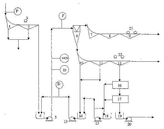
Prior to entering the process depicted in Figure 1, raw
coal may be reduced to 50mm top size. With reference to
Figure 1, raw coal is separated on a sieve bend 1 followed
by a vibratory screen 2 with wash water addition 3. This
device removes fine particles, typically less than 2-
0.2mm, from the raw coal and all the undersize is
processed in devices not mentioned here. The oversize
material gravitates to sump 4 from which it is pumped 5 to
the dense medium cyclone 6. It will be noted on Figure 1
that dense medium is added to the coarse coal particles in,
the dense medium cyclone feed sump 4. The coarse raw coal
is separated in the dense medium cyclone 6 to produce a
CA 02512902 2005-07-08
WO 2004/062809 PCT/AU2003/001727
- 20 -
lower ash product and a higher ash reject. The product is
separated from the dense medium on sieve bend 7 and drain
8 and rinse screen 9. The sieve bend and drain screens
remove the bulk of the dense medium which can then
recycled to the dense medium sump 14. The rinse screen 9
uses water addition 21, 22 (dirty and clarified) to aid
the removal of medium adhering to the coal particles.
Rinse screen underflow is significantly diluted and must
be concentrated such that the water is removed before it
can be reused in the operation of the dense medium
cyclone. Similar sieve bend 10, drain 11 and rinse 12
screen recovery of dense medium occurs for the dense
medium cyclone underflow material.
The diluted dense medium is dewatered with magnetic
separators 16 and 17. The recovered dense medium is
passed to the over-dense sump 18 from where ,it is pumped
15 to the dense medium sump 14. The separated water is
recycled for use elsewhere in the plant, including water
addition to the screening operations described above.
Also shown on Figure 1 are the locations of measuring
devices for medium density~D, pressure P, Medium to Coal
Ratio (MCR) and feed rate F.
It should be noted once again that this is a very brief
and simplified description of the generic circuitry for
coal processing.
The density of the dense medium supplied to the mixture
with the particulate material is measured with a nucleonic
or differential pressure transducer D. Two indicative
locations for measuring this parameter are indicated on
Figure 1.
The pressure of the medium density and particulate mixture
supplied to the dense medium cyclone is also measured by
pressure transducer P.
CA 02512902 2005-07-08
WO 2004/062809 PCT/AU2003/001727
- 21 -
The location of Medium to Coal Ratio measurement is also
shown and could be measured by the emerging electro-
impedance spectrometry technology which is not yet common
place in the industry.
In the preferred embodiment of the invention, the density
measurements made by the nucleonic or differential
pressure transducer D are used to generate an alarm
condition, should the medium induced partition coefficient
curve and/or parameters derived therefrom change from the
desired values so that remedial action can be taken to
restore the desired density control and thereby minimise
losses caused by fluctuations or variations in the density
of the medium density. However, as has been previously
described, the pressure measurements, Medium to Coal Ratio
measurements or feed rate measurements may be used in
combination with the density measurements or instead of
the density measurements in order to continually monitor
the fluctuations in medium induced partition coefficient
curve and/or parameters derived therefrom to enable the
alarm condition to be generated and remedial action
immediately taken to restore the required level of control
of the dense medium separation.
With reference to Figure 2, the density measurements from
the nucleonic or differential pressure transducer D are
fed to a processor 50, typically maintained in, but not
limited to, the coal plant operation room when in the
desired location, or any other suitable location. The
pressure and feed rate measurements from the pressure
transducer P and weightometers F are also fed to the
processor 50. Medium to Coal Ratio measurements from
electro-impedance spectrometry technology would also be
fed to the processor 50.
According to the preferred embodiment of the invention,
measurements are read frequently, for example every 1
CA 02512902 2005-07-08
WO 2004/062809 PCT/AU2003/001727
- 22 -
minute, and those measurements are taken over a
predetermined time period of, for example 30 minutes to
2.5 hours, may be used to determine the value set for
comparison with the predetermined value set in order to
determine whether the alarm condition needs to be
generated..
Table 1 below shows exemplary measurements which may be
taken over a time period of 9 hours and used for
processing in the processor 50.
CA 02512902 2005-07-08
WO 2004/062809 PCT/AU2003/001727
- 23 -
Table 1
Time Density Time Density Time Density
7:21:54 1571.48 7:49:28 1577.82 8:17:02 1530.05
7:22:29 1571.29 7:50:04 1568.54 8:17:38 1523.18
7:23:05 1568.14 7:50:40 1562.07 8:18:14 1520.75
7:23:41 1565.46 7:51:16 1554.97 8:18:50 1514.17
7:24:17 1560.24 7:51:52 1549.87 8:19:26 1523.2
7:24:53 1557.2 7:52:27 1544.62 8:20:02 1533.14
7:25:29 1557.36 7:53:03 1537.75 8:20:38 1532.79
7:26:05 1555.98 7:53:39 1526.34 8:21:14 1528.03
7:26:41 1552.94 7:54:15 1522.88 8:21:50 1521.08
7:27:17 1541.99 7:54:51 1521.17 8:22:25 1522.11
7:27:53 1535.55 7:55:27 1522.5 8:23:01 1520.89
7:28:29 1530.52 7:56:03 1521.06 8:23:37 1510.81
7:29:05 1524.52 7:56:39 1523.56 8:24:13 1498.6
7:29:41 1518.36 7:57:15 1524.7 8:24:49 1486.71
7:30:17 1508.26 7:57:51 1526.32 8:25:25 1464.58
7:30:53 1509.17 7:58:27 1525.81 8:26:01 1455.65
7:31:29 1524.88 7:59:03 1524.35 8:26:37 1446.62
7:32:05 1550.78 7:59:39 1522.54 8:27:13 1442.86
7:32:41 1563.68 8:00:15 1518.14 8:27:49 1463.41
7:33:17 1565.84 8:00:51 1513.85 8:28:25 1488.11
7:33:53 1563.41 8:01:27 1514.7 8:29:01 1508.38
7:34:29 1555.61 8:02:03 1525.43 8:29:37 1518.74
7:35:05 1552.5 8:02:39 1533.79 8:30:13 1529.76
7:35:41 1544.18 8:03:15 1543.44 8:30:49 1537.17
7:36:17 1539.94 8:03:51 1549.9 8:31:25 1536.6
7:36:53 1532.69 8:04:27 1548.61 8:32:01 1533.14
7:37:28 1526.97 8:05:03 1547.15 8:32:37 1525.17
7:38:04 1521.66 8:05:39 1545.95 8:33:13 1524.33
7:38:40 1519.88 8:06:15 1543.43 8:33:49 1522.95
7:39:16 1516.89 8:06:51 1539.92 8:34:25 1521.1
7:39:52 1501.46 8:07:26 1536.66 8:35:01 1519.82
7:40:28 1480.52 8:08:02 1531.5 8:35:37 1518.87
7:41:04 1471.89 8:08:38 1525.81 _ 1517.45
8:36:13
7:41:40 1473.86 8:09:14 1519.66 8:36:49 1515.65
7:42:16 1490.65 8:09:50 1513.08 8:37:24 1515.39
7:42:52 1511.69 8:10:26 1512.24 8:38:00 1518.52
7:43:28 1524.97 8:11:02 1515.62 8:38:36 1528.5
7:44:04 1548.59 8:11:38 1530.43 8:39:12 1541.7
7.:44:40 1580.46 8:12:14 1546.59 8:39:48 1540.91
7:45:16 1595.15 8:12:50 1547.2 8:40:24 1540.16
7:45:52 1611.78 8:13:26 1546.7 8:41:00 1537.56
7:46:28 1618.13 8:14:02 1545.82 8:41:36 1532.68
7:47:04 1622.66 8:14:38 1543.18 8:42:12 1523.01
7:47:40 1622.54 8:15:14 1541.39 8:42:48 1514.37
7:48:16 1618.63 8:15:50 1536.15 8:43:24 1512.51
7:48:52 1587.34 8:16:26 1532.97 8:44:00 1515.4
CA 02512902 2005-07-08
WO 2004/062809 PCT/AU2003/001727
- 24 -
Table 1. Cont (a)
Time Density Time Density Time Density
8:44:36 1528.01 9:12:10 1528.41 9:39:44 1590
8:45:12 1549.12 9:12:46 1533.87 9:40:20 1583.98
8:45:48 1566.6 9:13:22 1566.18 9:40:56 1583.16
8:46:24 1591.5 9:13:58 1591.25 9:41:32 1579.93
8:47:00 1582.88 9:14:34 1573.89 9:42:08 1577.61
8:47:36 1579.59 9:15:10 1572.24 9:42:44 1578.47
8:48:12 1572.02 9:15:46 1570.41 9:43:20 1578.01
8:48:48 1567 9:16:22 1562.4 9:43:56 1573.13
8:49:24 1566.1 9:16:58 1561.26 9:44:32 1567.29
8:50:00 1563.72 9:17:34 1560.41 9:45:08 1564.71
8:50:36 1559.59 9:18:10 1559.66 9:45:44 1560.32
8:51:12 1559.19 9:18:46 1558.07 9:46:20 1554.06
8:51:48 1553.49 9:19:22 1548.05 9:46:56 1545.22
8:52:23 1549.28 9:19:58 1542.21 9:47:32 1536.95
8:52:59 1543.38 9:20:34 1538.82 9:48:08 1531.57
8:53:35 1538.93 9:21:10 1531.64 9:48:44 1520.58
8:54:11 1531.98 9:21:46 1524.34 9:49:20 1514.83
8:54:47 1527.54 9:22:21 1521.97 9:49:56 1514.19
8:55:23 1520.06 9:22:57 1515.61 9:50:32 1526.09
8:55:59 1518.66 9:23:33 1509.27 9:51:08 1541.41
8:56:35 1512 9:24:09 1508.49 9:51:44 1544.95
8:57:11 1510.46 9:24:45 1517.54 9:52:19 1544.7
8:57:47 1516.8 9:25:21 1535.31 9:52:55 1543.15
8:58:23 1538.85 9:25:57 1546.61 9:53:31 1536.54
8:58:59 1556.67 9:26:33 1554.74 9:54:07 1532.97
8:59:35 1566.7 9:27:09 1562.12 9:54:43 1522.12
9:00:11 1560.83 9:27:45 1564.06 9:55:19 1501
9:00:47 1555.12 9:28:21 1574.38 9:55:55 1504.86
9:01:23 1553.18 9:28:57 1574.84 9:56:31 1515.49
9:01:59 1549.47 9:29:33 1566.97 9:57:07 1554.31
9:02:35 1549.32 9:30:09 1566.28 9:57:43 1594.72
9:03:11 1550.1 9:30:45 1561.85 9:58:19 1581.69
9:03:47 1551.14 9:31:21 1558.69 9:58:55 1578.96
9:04:23 1552.42 9:31:57 1549.33 9:59:31 1577.34
9:04:59 1550.17 9:32:33 1546.23 10:00:07 1571.28
9:05:35 1541.97 9:33:09 1539.1 10:00:43 1570.39
9:06:11 1539.53 9:33:45 1533.81 10:01:19 1569.2
9:06:47 1534.76 9:34:21 1525.34 10:01:55 1569.02
9:07:22 1532.91 9:34:57 1516.18 10:02:31 1568.81
9:07:58 1525.5 9:35:33 1507.14 10:03:07 1564.34
9:08:34 1520.57 9:36:09 1505.81 10:03:43 1557.1
9:09:10 1518.59 9:36:45 1518.01 10:04:19 1551.67
9:09:46 1512.5 9:37:20 1531.86 10:04:55 1547.28
9:10:22 1510.54 9:37:56 1554.32 10:05:31 1531.81
9:10:58 1509.42 9:38:32 1563.99 10:06:07 1530.39
9:11:34 1511.09 9:39:08 1576.83 10:06:43 1519.56
1
CA 02512902 2005-07-08
WO 2004/062809 PCT/AU2003/001727
- 25. -
Table 1. Cont (b)
Time Density Time Density Time Density
10:07:18 1514.21 10:34:53 1510.72 11:02:27 1508.63
10:07:54 1512.76 10:35:29 1529.87 11:03:03 1508.76
10:08:30 1519.42 10:36:05 1554.8 11:03:39 1510.07
10:09:06 1530.69 10:36:41 1568.52 11':04:15 1521.7
10:09:42 1544.09 10:37:16 1570 11:04:51 1534.43
10:10:18 1550.81 10:37:52 1569.09 11:05:27. 1560.22
10:10:54 1550.33 10:38:28 1567.52 11:06:03 1570.76
10:11:30 1548.65 10:39:04 1567.26 11:06:39 1581.18
10:12:06 1542.8 10:39:40 1576.85 11:07:14. 1575.61
10:12:42 1541.02 10:40:16 1581.32 11:07:50 1571.99
10:13:18 1537.74 10:40:52 1578.59 11:08:26 1570.68
10:13:54 1530.19 10:41:28 1570.35 11:09:02 1570.05
10:14:30 1528.48 10:42:04 1568.94 11:09:38 1567.74
10:15:06 1528.96 10:42:40 1567.89 11:10:14 1567.49
10:15:42 1529.01 10:43:16 1563.15 11:10:50 1566.11
10:16:18 1529.75 10:43:52 1561.13 11:11:26 1564.54
10:16:54 1530.13 10:44:28 1557.47 11:12:02 1561.24
10:17:30 1526.86 10:45:04 1555.12 11:12:38 1556.06
10:18:06 1521.66 10:45:40 1548.41 11:13:14 1549.86
10:18:42 1512.05 10:46:16 1540.41 11:13:50 1548.67
10:19:18 2510.26 10:46:52 1536.24 11:14:26 1533.39
10:19:54 1516.46 10:47:28 1524.24 11:15:02 1532.13
10:20:30 1529.82 10:48:04 1514.32 11:15:38 1527.21
10:21:06 1548.4 10:48:40 1513.28 11:16:14 1520.99
10:21:42 1561.94 10:49:16 1513.98 11:16:50 1514.18
10:22:17 1572.51 10:49:52 1531.54 11:17:26 1510
10:22:53 1569.01 10:50:28 1555.78 11:18:02 1510.96
10:23:29 1563.45 10:51:04 1563.7 11:18:38 1526.43
10:24:05 1562.52 10:51:40 1581.18 11:19:14 1548.92
10:24:41 1562.84 10:52:15 1590.08 11:19:50 1559.01
10:25:17 1564.35 10:52:51 1575.13 11:20:26 1559.8
10:25:53 1563.21 10:53:27 1573.64 11:21:02 1559.88
10:26:29 1561.2 10:54:03 1571.91 11:21:38 1557.63
10:27:05 1557.38 10:54:39 1569.33 11:22:13 1546.76
10:27:41 1554.12 10:55:15 1565.4 11:22:49 1522.9
10:28:17 1548.84 10:55:51 1565.82 11:23:25 1513.58
10:28:53 1545.58 10:56:27 1564.85 11:24:01 1501.81
10:29:29 1541.8 10:57:03 1563.39 11:24:37 1491.13
10:30:05 1539.85 10:57:39 1552.9 11:25:13 1511.48
10:30:41 1532.89 10:58:15 1544.92 11:25:49 1525.25
10:31:17 1526.82 10:58:51 1539.92 11:26:25 1547.59
10:31:53 1521.66 10:59:27 1533.3 11:27:01 1587.49
10:32:29 1519.89 11:00:03 1527.51 11:27:37 1615.3
10:33:05 1517.12 11:00:39 1526.38 11:28:13 1622.86
10:33:41 1508.57 11:01:15 1521.48 11:28:49_ 1623.28
10:34:17 1502.52 11:01:51 1518.69 11:29:25 1629.42
1
CA 02512902 2005-07-08
WO 2004/062809 PCT/AU2003/001727
- 26 -
Table 1. Cont (c)
Time Density Time Density Time Density
11:30:01 1627.97 11:57:35 1533.13 12:25:09 1509.23
11:30:37 1627.81 11:58:11 1550.87 12:25:45 1508.19
11:31:13 1610.47 11:58:47 1564.56 12:26:21 1520.57
11:31:49 1588.57 11:59:23 1587.36 12:26:57 1552.97
11:32:25 1580.53 11:59:59 1588.18 12:27:33 1568.78
11:33:01 1569.3 12:00:35 1581.23 12:28:09 1582.35
11:33:37 1561.99 12:01:11 1580.27 12:28:45 1574.04
11:34:13 1556.57 12:01:47 1578.79 12:29:21 1574.23
11:34:49 1546.36 12:02:23 1573.9 12:29:57 1571.59
11:35:25 1539.22 12:02:59 1567.59 12:30:33 1570.09
11:36:01 1532.02 12:03:35 1567.47 12:31:09 1553.8
11:36:37 1517.79 12:04:11 1567.51 12:31:45 1548.23
11:37:12 1504.21 12:04:47 1565.16 12:32:21 1548.2
11:37:48 1502.88 12:05:23 1554.35 12:32:57 1548.62
11:38:24 1508.15 12:05:59 1551.26 12:33:33 1547.59
11:39:00 1534.92 12:06:35 1544.48 12:34:09 1544.93
11:39:36 1542.27 12:07:10 1540.49 12:34:45 1538.97
11:40:12 1560.12 12:07:46 1528.76 12:35:21 1536.45
11:40:48 1561.58 12:08:22 1523.15 12:35:57 1530.41
11:41:24 1569.31 12:08:58 1520.7 12:36:33 1528.81
11:42:00 1602.57 12:09:34 1517.39 12:37:08 1525.79
11:42:36 1630.03 12:10:10 1510.07 12:37:44 1524.42
11:43:12 1623.15 12:10:46 1516.29 12:38:20 1512.65
11:43:48 1614.47 12:11:22 1531.6 12:38:56 1513.54
11:44:24 1611.08 12:11:58 1548.3 12:39:32 1525.07
11:45:00 1610.18 12:12:34 1552.85 12:40:08 1541.86
11:45:36 1608.51 12:13:10 1554.14 12:40:44 1563.75
11:46:12 1607.48 12:13:46 1554.02 12:41:20 1569.69
11:46:48 1598.75 12:14:22 1550.23 12:41:56 1569.45
11:47:24 1591.39 12:14:58 1542.21 12:42:32 1568.11
11:48:00 1585.69 12:15:34 1540.48 12:43:08 1561.01
11:48:36 1580.62 12:16:10 1533.69 12:43:44 1555.42
11:49:12 1576.74 12:16:46 1528.04 12:44:20 1551.74
11:49:48 1571.49 12:17:22 1507.88 12:44:56 1544.76
11:50:24 1565.49 12:17:58 1533.74 12:45:32 1540.13
11:51:00 1557.92 12:18:34 1544.35 12:46:08 1538.53
11:51:36 1549.07 12:19:10 1545.04 12:46:44 1529.59
11:52:11 1542.65 12:19:46 1542.53 12:47:20 1523.21
11:52:47 1540.23 12:20:22 1538.79 12:47:56 1519.08
11:53:23 1531.1 12:20:58 1539.43 12:48:32 1514.1
11:53:59 1529.78 12:21:34 1537.63 12:49:08 1513.1
11:54:35 1520.32 12:22:09 1533.7 12:49:44 1502.05
11:55:11 1517.97 12:22:45 1526.92 12:50:20 1526.46
11:55:47 1513.61 12:23:21 1522.59 12:50:56 1586.25
11:56:23 1513.7 12:23:57 1519.81 12:51:32 1620.56
11:56:59 1515.11 12:24:33 1516.35 12:52:07 1614
CA 02512902 2005-07-08
WO 2004/062809 PCT/AU2003/001727
- 27 -
Table 1. Cont (d)
Time Density Time Density Time Density
12:52:43 1601.39 13:20:18 1558.59 13:47:52 1526.17
12:53:19 1601.76 13:20:54 1557.39 13:48:28 1521.69
12:53:55 1603.86 13:21:30 1556.18 13:49:04 1512.85
12:54:31 1602.71 13:22:05 1555.23 13:49:40 1511.38
12:55:07 1601.32 13:22:41 1551.83 13:50:16 1515.48
12:55:43 1593.09 13:23:17 1540.64 13:50:52 1541.15
12:56:19 1585.93 13:23:53 1540.09 13:51:28 1559.98
12:56:55 1579.51 13:24:29 1538.82 13:52:03 1564.4
12:57:31 1574.21 13:25:05 1533.68 13:52:39 1565.1
12:58:07 1566.15 13:25:41 1526.91 13:53:15 1564.1
12:58:43 1556.04 13:26:17 1521.88 13:53:51 1549.58
12:59:19 1554.77 13:26:53 1513.14 13:54:27 1538.78
12:59:55 1553.03 13:27:29 1508.49 13:55:03 1542.46
13:00:31 1545.92 13:28:05 1514.39 13:55:39 1530.63
13:01:07 1539.03 13:28:41 1523.07 13:56:15 1528.54
13:01:43 1532.93 13:29:17 1546.83 13:56:51 1529.15
13:02:19 1531.59 13:29:53 1556.79 13:57:27 1526.71
13:02:55 1529.45 13:30:29 1567.5 13:58:03 1517.29
13:03:31 1522.97 13:31:05 1570.72 13:58:39 1515.54
13:04:07 1517.31 13:31:41 1559.43 13:59:15 1513.46
13:04:43 1514.11 13:32:17 1558.85 13:59:51 1520.17
13:05:19 1514.84 13:32:53 1558.8 14:00:27 1538.61
13:05:55 1520.18 13:33:29 1557.27 14:01:03 1554.4
13:06:31 1527.69 13:34:05 1555.6 14:01:39 1554.12
13:07:06 1538.51 13:34:41 1553.93 14:02:15 1554.73
13:07:42 1551.43 13:35:17 1551.62 14:02:51 1555.26
13:08:18 1568.34 13:35:53 1541.33 14:03:27 1549.32
13:08:54 1576.6 13:36:29 1539.14 14:04:03 1542.55
13:09:30 1567.74 13:37:04 1531.42 14:04:39 1540.98
13:10:06 1565.52 13:37:40 1527.56 14:05:15 1539.91
13:10:42 1563.96 13:38:16 1523.44 14:05:51 1539.78
13:11:18 1554.28 13:38:52 1514.91 14:06:27 1538.13
13:11:54 1553.32 13:39:28 1512.32 14:07:02 1529.42
13:12:30 1552.24 13:40:04 1513.59 14:07:38 1524.8
13:13:06 1545.65 13:40:40 1528.29 14:08:14 1515.33
13:13:42 1538.04 13:41:16 1547.55 14:08:50 1514.53
13:14:18 1531.52 13:41:52 1554.59 14:09:26 1518.01
13:14:54 1526.32 13:42:28 1556.7 14:10:02 1535.99
13:15:30 1516.27 13:43:04 1555.7 14:10:38 1550.72
13:16:06 1513.4 13:43:40 1555.02 14:11:14 1550.79
13:16:42 1514.22 13:44:16 1553.05 14:11:50 1545.1
13:17:18 1524.64 13:44:52 1544.86 14:12:26 1535.62
13:17:54 1541.47 13:45:28 1535.24 14:13:02 1529.48
13:18:30 1558.07 13:46:04 1534.7 14:13:38 1525.68
13:19:06 1560.21 13:46:40 1527.93 14:14:14 1514.88
13:19:42 1559.52 13:47:16 1526.32 14:14:50 1513.7
CA 02512902 2005-07-08
WO 2004/062809 PCT/AU2003/001727
- 28 -
Table 1. Cont (e)
Time Density Time Density Time Density
14:15:26 1515.88 14:43:00 1613.52 15:10:34 1642.76
14:16:02 1528.14 14:43:36 1601.23 15:11:10 1641.49
14:16:38 1561.81 14:44:12 1597.73 15:11:46 1640.13
14:17:14 1568.32 14:44:48 1594.25 15:12:22 1632.55
14:17:50 1557.94 14:45:24 1593.59 15:12:58 1631.12
14:18:26 1558.18 14:46:00 1585.3 15:13:34 1629.79
14:19:02 1555.92 14:46:36 1582.45 15:14:10 1626.76
14:19:38 1556.49 14:47:12 1581.75 15:14:46 1620.1
14:20:14 1556.02 14:47:48 1574.28 15:15:22 1612.22
14:20:50 1555.68 14:48:24 1569.78 15:15:58 1603.53
14:21:26 1550.04 14:49:00 1560.16 15:16:34 1596.14
14:22:01 1543.23 14:49:36 1552.86 15:17:10 1586.7
14:22:37 1537.92 14:50:12 1541.55 15:17:46 1577.42
14:23:13 1528.89 14:50:48 1538.76 15:18:22 1568.21
14:23:49 1525.98 14:51:24 1530.33 15:18:58 1563.21
14:24:25 1519.11 14:51:59 1523.89 15:19:34 1561.99
14:25:01 1515.97 14:52:35 1520.8 15:20:10 1550.79
14:25:37 1512.44 14:53:11 1515.33 15:20:46 1543.95
14:26:13 1511.67 14:53:47 1509.78 15:21:22 1537.67
14:26:49 1516.37 14:54:23 1508.79 15:21:57 1530.23
14:27:25 1531.43 14:54:59 1516.99 15:22:33 1521.37
14:28:01 1547.17 14:55:35 1539.54 15:23:09 1513.18
14:28:37 1562..37 14:56:11 1561.1 15:23:45 1512.23
14:29:13 1569.31 14:56:47 1570.26 15:24:21 1519.37
14:29:49 1573.25 14:57:23 1579.62 15:24:57 1530.3
14:30:25 1572.26 14:57:59 1586.85 15:25:33 1558.55
14:31:01 1570.36 14:58:35 1587.4 15:26:09 1569.79
14:31:37 1564.07 14:59:11 1586 15:26:45 1571.16
14:32:13 1557.66 14:59:47 1584.18 15:27:21 1576.17
14:32:49 1557.39 15:00:23 1564.69 15:27:57 1575.97
14:33:25 1557.44 15:00:59 1542.28 15:28:33 1569.29
14:34:01 1557.17 15:01:35 1533.94 15:29:09 1565.26
14:34:37 1556.64 15:02:11 1522.08 15:29:45 1557.01
14:35:13 1555.3 15:02:47 1520.29 15:30:21 1550.25
14:35:49 1551.1 15:03:23 1516.89 15:30:57 1547.64
14:36:25 1543.87 15:03:59 1511.1 15:31:33 1546.99
14:37:00 1529.51 15:04:35 1504.9 15:32:09 1540.65
14:37:36 1526.11 15:05:11 1499.99 15:32:45 1532.65
14:38:12 1521.3 15:05:47 1517.2 15:33:21 1526.54
14:38:48 1514.25 15:06:23 1521.46 15:33:57 1519.66
14:39:24 1512.46 15:06:58 1529.45 15:34:33 1513.74
14:40:00 1509.48 15:07:34 1545.4 15:35:09 1516.67
14:40:36 1512.16 15:08:10 1576.52 15:35:45 1520.25
14:41:12 1521.87 15:08:46 1610.76 15:36:21 1533.79
14:41:48 1557 15:09:22 1619.6 15:36:56 1548.99
14:42:24 1605.18 15:09:58 1635.18 15:37:32 1548.27
CA 02512902 2005-07-08
WO 2004/062809 PCT/AU2003/001727
- 29 -
Table 1. Cont (f)
Time Density Time Density Time Density
15:38:08 1541.54 16:05:43 1554
15:38:44 1536.82 16:06:19 1551.15
15:39:20 1529.14 16:06:54 1550.61
15:39:56 1518.88 16:07:30 1550.99
15:40:32 1512.68 16:08:06 1549.3
15:41:08 1508.48 16:08:42 1544.41
15:41:44 1514.94 16:09:18 1539.01
15:42:20 1551.58 16:09:54 1531.55
15:42:56 1597.5 16:10:30 1525.98
15:43:32 1580.9 16:11:06 1521.31
15:44:08 1577.17 16:11:42 1513.79
15:44:44 1576.19 16:12:18 1509.34
15:45:20 1575.9 16:12:54 1523.44
15:45:56 1574.46 16:13:30 1539.94
15:46:32 1572.2 16:14:06 1556.73
15:47:08 1571.52 16:14:42 1557.62
15:47:44 1570.77 16:15:18 1554.25
15:48:20 1560.67 16:15:54 1547.7
15:48:56 1554.55 16:16:30 1543.48
15:49:32 1549.06 16:17:06 1530.16
15:50:08 1543.45 16:17:42 1523.43
15:50:44 1537.69 16:18:18 1521.88
15:51:20 1531.33 16:18:54 1520.07
15:51:55 1523.09 16:19:30 1511.82
15:52:31 1511.24 16:20:06 1511.38
15:53:07 1513.81 16:20:42 1516.9
15:53:43 1521.84 16:21:18 1547.85
15:54:19 1539.68 16:21:53 1594.85
15:54:55 1557.55
15:55:31 1558.06
15:56:07 1557.15
15:56:43 1555.45
15:57:19 1553.53
15:57:55 1544.92
15:58:31 1531.07
15:_59':07_1529.55
15:59:43 1525.89
16:00:19 1517.64
16:00:55 1514.72
16:01:31 1514.73
16:02:07 1515.93
16:02:43 1546.66
16:03:19 1562.99
16:03:55 1554.84
16:04:31 1554.78
16:05:07 1554.41
CA 02512902 2005-07-08
WO 2004/062809 PCT/AU2003/001727
- 30 -
In table 2 set out below, the normalised frequency
distribution of the densities given in Table 1 are set
out.
The normalised frequency is obtained by multiplying the
frequency value by 100 and dividing by the sum of the
normalised frequency column. The cumulative normalised
frequency is the addition of the particular normalised
frequency by the sum of the previous normalised
frequencies.
CA 02512902 2005-07-08
WO 2004/062809 PCT/AU2003/001727
- 31 -
TP~8LE 2
Frequency
Distribution
Density Frequency Normalised Cumulative
Range
Frequency Normalised
fre uenc
Lower U er Mean Densit
k /m3 k /m3
1442 0 0.000 0.000
1442 1443 1442.5 1 0.111 0.111
1443 1444 1443.5 0 0.000 0.111
1444 1445 1444.5 0 0.000 0.111
1445 1446 1445.5 0 0.000 0.111
1446 1447 1446.5 1 0.111 0.222
1447 1448 1447.5 0 0.000 0.222
1448 1449 1448.5 0 0.000 0.222
1449 1450 1449.5 0 0.000 0.222
1450 1451 1450.5 0 0.000 0.222
1451 1452 1451.5 0 0.000 0.222
1452 1453 1452.5 0 0.000 0.222
1453 1454 1453.5 0 0.000 0.222
1454 1455 1454.5 0 0.000 0.222
1455 1456 1455.5 1 0.111 0.333
1456 1457 1456.5 0 0.000 0.333
1457 1458 1457.5 0 0.000 0.333
1458 1459 1458.5 0 0.000 0.333
1459 1460 1459.5 0 0.000 0.333
1460 1461 1460.5 0 0.000 0.333
1461 1462 1461.5 0 0.000 0.333
1462 1463 1462.5 0 0.000 0.333
1463 1464 1463.5 1 0.111 0.443
1464 1465 1464.5 1 0.111 0.554
1465 1466 1465.5 0 0.000 0.554
1466 1467 1466.5 0 0.000 0.554
1467 1468 1467.5 0 0.000 0.554
1468 1469 1468.5 0 0.000 0.554
1469 1470 1469.5 0 0.000 0.554
1470 1471 1470.5 0 0.000 0.554
1471 1472 1471.5 1 0.111 0.665
1472 1473 1472.5 0 0.000 0.665
1473 1474 1473.5 1 0.111 0.776
1474 1475 1474.5 0 0.000 0.776
1475 1476 1475.5 0 0.000 0.776
1476 1477 1476.5 0 0.000 0.776
1477 1478 1477.5 0 0.000 0.776
1478 1479 1478.5 0 0.000 0.776
1479 1480 1479.5 0 0.000 0.776
1480 1481 1480.5 1 0.111 0.887
CA 02512902 2005-07-08
WO 2004/062809 PCT/AU2003/001727
- 32 -
1481 1482 1481.5 0 0.000 0.887
1482 1483 1482.5 0 0.000 0.887
1483 1484 1483.5 0 0.000 0.887
1484 1485 1484.5 0 0.000 0.887
1485 1486 1485.5 0 0.000 0.887
1486 1487 1486.5 1 0.111 0.998
1487 1488 1487.5 0 0.000 0.998
1488 1489 1488.5 1 0.111 1.109
1489 1490 1489.5 0 0.000 1.109
1490 1491 1490.5 1 0.111 1.220
1491 1492 1491.5 1 0.111 1.330
1492 1493 1492.5 0 0.000 1.330
1493 1494 1493.5 0 0.000 1.330
1494 1495 1494.5 0 0.000 1.330
1495 1496 1495.5 0 0.000 1.330
1496 1497 1496.5 0 0.000 1.330
1497 1498 1497.5 0 0.000 1.330
1498 1499 1498.5 1 0.111 1.441
1499 1500 1499.5 1 0.111 1.552
1500 1501 1500.5 0 0.000 1.552
1501 1502 1501.5 3 0.333 1.885
1502 1503 1502.5 3 0.333 2.217
1503 1504 1503.5 0 0.000 2.217
1504 1505 1504.5 3 0.333 2.550
1505 1506 1505.5 1 0.111 2.661
1506 1507 1506.5 0 0.000 2.661
1507 1508 1507.5 2 0.222 2.882
1508 1509 1508.5 11 1.220 4.102
1509 1510 1509.5 7 0.776 4.878
1510 1511 1510.5 9 0.998 5.876
1511 1512 1511.5 9 0.998 6.874
1512 1513 1512.5 14 1.552 8.426
1513 1514 1513.5 18 1.996 10.421
1514 1515 1514.5 20 2.217 12.639
1515 1516 1515.5 14 1.552 14.191
1518 1517 1518.5 12 1.330 15.521
1517 1518 1517.5 10 1.109 16.630
1518 1519 1518.5 11 1.220 17.849
1519 1520 1519.5 11 1.220 19.069
1520 1521 1520.5 15 1.663 20.732
1521 1522 1521.5 19 2.106 22.838
1522 1523 1522.5 10 1.109 23.947
1523 1524 1523.5 12 1.330 25.277
1524 1525 1524.5 11 1.220 26.497
1525 1526 1525.5 13 1.441 27.938
1526 1527 1526.5 17 1.885 29.823
1527 1528 1527.5 6 0.665 30.488
1528 1529 1528.5 13 1.441 31.929
1529 1530 1529.5 15 1.663 33.592
CA 02512902 2005-07-08
WO 2004/062809 PCT/AU2003/001727
- 33 -
1530 1531 1530.5 13 1.441 35.033
1531 1532 1531.5 16 1.774 36.807
1532 1.533 1532.5 11 . 1.220 38.027
1533 1534 1533.5 14 1.552 39.579
1534 1535 1534.5 4 0.443 40.022
1535 1536 1535.5 5 0.554 40.576
1536 1537 1536.5 8 0.887 41.463
1537 1538 1537.5 8 0.887 42.350
1538 1539 1538.5 13 1.441 43.792
1539 1540 1539.5 16 1.774 45.565
1540 1541 1540.5 11 1.220 46.785
1541 1542 1541.5 13 1.441 48.226
1542 1543 1542.5 9 0.998 49.224
1543 1544 1543.5 10 1.109 50.333
1544 1545 1544.5 13 1.441 51.774
1545 1546 1545.5 9 0.998 52.772
1546 1547 1546.5 9 0.998 53.769
1547 1548 1547.5 10 1.109 54.878
1548 1549 1548.5 15 1.663 56.541
1549 1550 i 549.5 13 1.441 57.982
1550 1551 1550.5 14 1.552 59.534
i 551 1552 1551.5 10 1.109 60.643
1552 1553 1552.5 8 0.887 61.530
1553 1554 1553.5 8 0.887 62.417
1554 1555 1554.5 22 2.439 64.856
1555 1556 1555.5 15 1.663 66.519
1556 1557 1556.5 11 1.220 67.738
1557 1558 1557.5 19 2.106 69.845
1558 1559 1558.5 9 0.998 70.843
1559 1560 1559.5 9 0.998 71.840
1560 1561 1560.5 9 0.998 72.838
1561 1562 1561.5 12 1.330 74.169
1562 1563 1562.5 7 0.776 74.945
1563 1564 1563.5 12 1.330 76.275
1564 1565 1564.5 11 1.220 77.494
1565 1566 1565.5 9 0.998 78.492
1566 1567 1566.5 8 0.887 79.379
1567 1568 1567.5 12 1.330 80.710
1568 1569 1568.5 10 1.109 81.818
1569 1570 1569.5 13 1.441 83.259
1570 1571 1570.5 12 1.330 84.590
1571 1572 i 571.5 9 0.998 85.588
1572 1573 1572.5 5 0.554 86.142
1573 1574 1573.5 5 0.554 86.696
1574 1575 1574.5 7 0.776 87.472
1575 1576 1575.5 4 0.443 87.916
1576 1577 1576.5 7 0.776 88.692
1577 1578 1577.5 5 0.554 89.246
1578 1579 1578.5 5 0.554 89.800
CA 02512902 2005-07-08
WO 2004/062809 PCT/AU2003/001727
- 34 -
1579 1580 1579.5 4 0.443 90.244
1580 1581 1580.5 5 0.554 90.798
1581 1582 1581.5 6 0.665 91.463
1582 1583 1582.5 3 0.333 91.796
1583 1584 1583.5 2 0.222 92.018
1584 1585 1584.5 1 0.111 92.129
1585 1586 1585.5 3 0.333 92.461
1586 1587 1586.5 4 0.443 92.905
1587 1588 1587.5 4 0.443 93.348
1588 1589 1588.5 2 0.222 93.570
1589 1590 1589.5 0 0.000 93.570
1590 1591 1590.5 2 0.222 93.792
1591 1592 1591.5 3 0.333 94.124
1592 1593 1592.5 0 0.000 94.124
1593 1594 1593.5 2 0.222 94.346
1594 1595 1594.5 3 0.333 94.678
1595 1596 1595.5 1 0.111 94.789
1596 1597 1596.5 1 0.111 94.900
1597 1598 1597.5 2 0.222 95.122
1598 1599 1598.5 1 0.111 95.233
1599 1600 1599.5 0 0.000 95.233
1600 1601 1600.5 0 0.000 95.233
1601 1602 1601.5 4 0.443 95.676
1602 1603 1602.5 2 0.222 95.898
1603 1604 1603.5 2 0.222 96.120
1604 1605 1604.5 0 0.000 96.120
1605 1606 1605.5 1 0.111 96.231
1606 1607 1606.5 0 0.000 96.231
1607 1608 1607.5 1 0.111 96.341
1608 1609 1608.5 1 0.111 96.452
1609 1610 1609.5 0 0.000 96.452
1610 1611 1610.5 3 0.333 96.785
1611 1612 1611,.5 2 0.222 97.007
1612 1613 1612.5 1 0.111 97.118
1613 1614 1613.5 1 0.111 97.228
1614 1615 1614.5 2 0.222 97.450
1615 1616 1615.5 1 0.111. 97.561
1616 1617 1616.5 0 0.000 97.561
1617 1618 1617.5 0 0.000 97.561
1618 1619 1618.5 2 0.222 97.783
1619 1620 1619.5 1 0.111 97.894
1620 1621 1620.5 2 0.222 98.115
1621 1622 1621.5 0 0.000 98.115
1622 1623 1622.5 3 0.333 98.448
1623 1624 1623.5 2 0.222 98.670
1624 1625 1624.5 0 0.000 98.670
1625 1626 1625.5 0 0.000 98.670
1626 1627 1626.5 1 0.111 98.780
1627 1628 1627.5 2 0.222 99.002
CA 02512902 2005-07-08
WO 2004/062809 PCT/AU2003/001727
- 35 -
1628 1629 1628.5 0 0,000 99.002
1629 1630 1629.5 2 0.222 . 99.224
1630 1631 1630.5 1 0.111 99.335
1631 1632 1631.5 1 0.111 99.446
'
1632 1633 1632.5 1 0.111 99.557
1633 1634 1633.5 0 0.000 99.557
1634 1635 1634.5 0 ~ 0.000 99.557
1635 1636 1635.5 1 0.111 99,667
1636 1637 1636.5 0 0.000 99.667
1637 1638 1637.5 0 0.000 99.667
1638 1639 1638.5 0 0.000 99.667
1639 1640 1639.5 0 0.000 99.667
1640 1641 1640.5 1 0.111 99.778
1641 1642 1641.5 1 0.111 99.889
1642 1643 1642.5 1 0.111 100.000
1643 1644 1643.5 0 0.000 100.000
1644 1645 1644.5 0 0.000 100.000
1645
Totai = Total =
902
100.000
The processor 50 then lines up the measured density values
from lowest to highest so that the frequency of each
measured value can be determined.
A chart is then prepared whereby the mid point of each
density range is plotted against the density to give the
partition coefficient curve.
The processor 50 then determines an induced value, which
in the preferred embodiment uses the density measurements
is a medium induced Ep value from the cumulative frequency
distribution of the length of time spent at each density
by taking the absolute value of the difference in density
at the 75th and 25th percentiles and dividing by 2000 as
shown by the following equation:
Equation
Ep = absolute value (Density at 75th percentile - Density
at 25th percentile)/2000
By way of further explanation, the inefficiency of the
CA 02512902 2005-07-08
WO 2004/062809 PCT/AU2003/001727
- 36 -
processing is generally given by the Ep value. Figure 3
is a graph in an ideal situation where perfect separation
results in correct placement of all material in the feed
that should report to product reporting to product and all
material in feed that should report to reject reporting to
reject. If the above equation is applied to the data in
Figure 3, it will be seen that the Ep value is 0, which
gives a theoretically perfect result. However, in real
operating conditions, the graph of Figure 3 is more likely
to look like that shown in Figure 4 Using the data
supplied ,in Table 2 and Figure 4, the Ep value is (1,562.5
- 1523.5)/2000, which equals 0.0195. The processor 50 is
programmed to generate an alarm, should the calculated Ep
value become, for example, 0.025. Thus, the graph shown
1.5 in Figure 4 is indicative of a acceptable MIEp value in
this context indicating that remedial action does not need
to be taken. If the value was above 0.025, an alarm
condition would be generated. As shown in Figure 2, the
processor may output a signal to an alarm 52 to generate
the alarm, which could be an audible alarm or simply a
visual indication on a monitor or a combination of both to
alert operators in the control room that fluctuations have
exceeded a desired value and that remedial action should
be taken to correct the situation to restore the proper
medium density, and thereby restore maximum yield
operation to the processing plant.
The remedial action which may be taken may be to dispatch
workmen to inspect valves in the system to ensure that
they are operating properly and have not jammed or closed,
pipelines to ensure that there are no leakages, and other
operating parameters of the equipment. Action can be
taken by workmen to correct any fault which may be
observed immediately, rather than awaiting routine
inspections or the like which may result in a fault
continuing for a continued period of time, and thereby
resulting in significant loss in the yield from the plant
until the remedial action is identified and taken.
CA 02512902 2005-07-08
WO 2004/062809 PCT/AU2003/001727
- 37 -
The remedial action may also take the form of an automated,
response, for example~the remedial action may be to invoke
a control system retune algorithm to optimise PID control
system values.
MIEp values are periodically determined after an initial
period of 9 hours by simply dropping off the first
measurement made and adding to the total of measurements °
the next successive measurement made. For example, in
Table 1, the next MIEp value may be calculated by dropping
off the density reading for the time 7:21:54 and adding to
the list of density values measured that for time period
16:21:53. This would provide a new MIEp value for
comparison with the predetermined value every 36 seconds.
Obviously, if a greater period is desired, then additional
earlier readings can be ignored and more subsequent
measurements made before a further MIEp value is
calculated. Also, if measurements of MIEp over a shorter
period are desired, density data would be collected for
the shorter period and used in a manner similar to that
presented above.
An additional example is given with the same data as shown
in Table 1 for the situation where measurements of MIEp
over a shorter period are required. For a rolling period
of 90 minutes a rolling MIEp can be calculated. It is
then possible to plot rolling MIEp as ordinate and time as
abscissa.
In accordance with the preferred embodiment of the
invention, the processing plant can be monitored to
determine when its separating performance drops below
required levels, thereby enabling remedial action to be
immediately taken, and this could be worth millions of
dollars per annum to the operation. The monitoring can
take the form of a run chart of MIEp in which upper and
lower control limits can be derived. Derivation above the
CA 02512902 2005-07-08
WO 2004/062809 PCT/AU2003/001727
- 38 -
upper control limit can be used as the signal for
corrective action in the processor 50. Also, the run
charts of MIEp can be used as a benchmarking tool to
compare control systems within a given plant, and also
between plants.
In the second embodiment of the invention in which the
pressure measurements are taken so as to produce a
pressure induced Ep value, a similar algorithm to that
described above is used with the inclusion of a
theoretically and/or empirically determined relationship
between pressure and separating density. Alternatively,
the pseudo PIEp concept can be used. The pressure values
are measured at the time intervals similar to that in
Figure 1. The separating density is a function of the
pressure and therefore the pressure values can be
converted to separating density values via an appropriate
empirical or theoretical calibration which are accumulated
in the same manner as described with reference to Table 2
so as to enable the Ep value to be calculated.
Similarly, in the embodiment which uses feed rate, the
feed rate of material is measured as, for example, weight
in tonnes per hour, and these values are again converted
to separation density values so that an accumulation of
separation densities can be used to enable the feed rate
induced Ep value to be determined. Alternatively, the
pseudo FRIEp concept can be used.
Similarly, in the embodiment which uses Medium to Coal
Ratio, the Medium to Coal Ratio is measured as, for
example, cubic meters of medium per hours divided by
weight in tonnes per hour of dense medium cyclone feed,
and these values are again converted to separation density
values so that an accumulation of separation densities can
be used to enable the Medium to Coal Ratio induced Ep
value to be determined. Alternatively, the, pseudo MCRIEp
concept can be used.
CA 02512902 2005-07-08
WO 2004/062809 PCT/AU2003/001727
- 39 -
For the example given above, the detailed calculations
presented indicated that the medium induced Ep was 0.0195_
Following similar lines, it is possible to calculate a
pressure induced Ep = 0.002. At the same time, the
measured Ep for coal was 0.026. This is interpreted as
about 70% of the Ep was due to medium density variation
and about 7% was due to pressure variation.
The additional interpretation of the invention is that the
large proportion of the actual separating inefficiencies
of the dense medium separator is due to process variation
and can be measured with relative ease in most modern
processing facilities. Also, if the MIEp=0.0195 then the
Ep of the coal cannot be smaller than 0.0195, arid so the
invention also permits the lower limit of coal separating
efficiency to be measured with relative ease on-line.
Since modifications within the spirit and scope of the
invention may readily be effected by persons skilled
within the art, it is to be understood that this invention,
is not limited to the particular embodiment described by
way of example hereinabove.
In the claims which follow and in the preceding
description of the invention, except where the context
requires otherwise due to express language or necessary
implication, the word "comprise", or variations such as
°comprises" Or "comprising°, is used Ln an 3.nCluS,7.ve
sense, ie. to specify the presence of the stated features
but not to preclude the presence or addition of further
features in various embodiments of the invention.