Note : Les descriptions sont présentées dans la langue officielle dans laquelle elles ont été soumises.
CA 02512921 2005-07-08
WO 2004/065869 PCT/AU2003/001623
-1-
"A Refrigeration Process and the Prods~ction of ~Liq~efied Natural Gas"
Field of the Invention
The present invention relates to a refrigeration process. More particularly,
the
refrigeration process of the present invention has particular application in
the
production of liquefied natural gas.
Background Art
Traditional processes for the production of liquefied natural gas (hereinafter
"LNG") comprise, in broad terms, a natural gas pre-treatment stage and a gas
liquefaction stage. The pre-treatment stage is required to remove components
of
the gas stream that will freeze solid at cryogenic temperatures. Examples of
components removed for this reason are carbon dioxide, hydrogen sulphide,
heavy hydrocarbons and water. Carbon dioxide and/or hydrogen sulphide is
typically removed in an absorption process (for example using amine) and/or
membrane process; heavy hydrocarbons removed ~by cooling and condensing,
and water removed in a dehydration process (for example using molecular
sieves). Such pre-treatment may either require or cause the gas to be heated
to
about 50°C.
The liquefaction stage of the process comprises both cryogenic heat exchange
and refrigeration. The pre-treatment stage provides 'sweet dry' gas which is
passed through a heat exchanger and expansion valve, where it is cooled to
about -150°C (depending upon gas composition and storage pressure),
liquefied
and transferred to storage. A variety of refrigeration methods using various
refrigerants and processes are known.
In one example of the prior art (typically for small scale plants) the
refrigeration
step comprises each of a standard compression, cooling by air or water and an
expander cycle, in which most refrigeration is provided by the isentropic
expansion of a recycle stream. A turbo expander-compressor is used to recover
power from gas expansion and the refrigerant is further compressed in main gas
CA 02512921 2005-07-08
WO 2004/065869 PCT/AU2003/001623
-2-
driven booster compressors. Warm refrigerant is pre-cooled by cold refrigerant
gas prior to entering the expander cycle so that the necessary cryogenic
temperatures can be achieved.
In another example of the prior art (typically for larger plants), two
refrigerant
cycles are provided. Each cycle has its own compressor drive (traditionally
using
gas turbines but could equally use electric drives powered by gas turbine
generators). The "first" cycle is used to pre-cool the natural gas as well as
pre-
cool the "second" lower temperature cycle. Refrigerant for the first cycle
typically
uses propane or mixed refrigerant.
Typically employed processes for the production of LNG as described above
presently have substantial energy requirements for cooling and liquefaction of
the
natural gas. Alternatively, if a more energy efficient process is selected,
that"
process will be very expensive in terms of initial capital costs. This energy
is
supplied by mechanical drives that use prime movers, such as gas turbines, gas
engines and/or electric motors, to drive compressors for the necessary
refrigeration processes. The prime movers are inherently very inefficient and
are
known to typically convert only 25 - 40% of the energy supplied as fuel into
useful
compressive work for the refrigeration process. The majority of energy is lost
to
atmosphere in the form of heat. As such, presently available processes for LNG
production are very inefficient.
In known LNG processes the feed natural gas is typically pre-treated to remove
carbon dioxide, heavy hydrocarbons and water prior to liquefaction. This pre-
treatment requires heating in a solvent absorption or membrane system. As a
result, further cooling energy is then required to liquefy the natural gas.
The process for the production of liquefied natural gas of the present
invention
has as one object thereof to overcome substantially the abovementioned
problems of the prior art, or to at least provide a useful alternative
thereto.
Throughout the specification, unless the context requires otherwise, the word
"comprise" or variations such as "comprises" or "comprising", will be
understood to .
CA 02512921 2005-07-08
WO 2004/065869 PCT/AU2003/001623
-3-
imply the inclusion of a stated integer or group of integers but not the
exclusion of
any other integer or group of integers.
The preceding discussion of the background art is intended to facilitate an
understanding of the present invention only. It should be appreciated that the
discussion is not an acknowledgement or admission that any of the material
referred to was part of the common general knowledge in Australia or any other
country and/or region as at the priority date of the application.
Disclosure of the Inverotioc~
In accordance with the present invention there is provided a process for the
production of liquefied natural gas utilising a refrigeration cycle, the
process
characterised by the steps of:
i) Pre-treatment of a natural gas stream;
ii) Chilling of either or both of the resulting pre-treated gas stream or a
refrigerant gas stream within the refrigeration cycle; and
iii) Liquefaction of the natural gas.
Preferably, the chilling step is driven at least in part by waste heat from
the
liquefaction step. The waste heat may comprise hot jacket water and/or hot
exhaust gases from the main gas engine or turbine driven compressor.
Additionally, heat may also be provided from one or more of the group of prime
movers, compressors, burning of flare or other waste gases or liquids, and
solar
powe r.
Still preferably, waste heat from the liquefaction step is utilised, at least
in part, in
the gas pre-treatment step.
The chilling step may further condense certain components of the pre-treated
natural gas stream. Components of the natural gas stream condensed in this
manner may include water, heavy hydrocarbons and/or carbon dioxide.
CA 02512921 2005-07-08
WO 2004/065869 PCT/AU2003/001623
-4-
Further preferably, the chilling step cools the gas stream to a temperature of
between about -80°C and 10°C. The chilling of the pre-treated
gas stream is
preferably conducted in a number of stages so as to allow the selective
condensation and removal of various components thereof.
The chilling of the refrigerant gas stream may cause some components in the
refrigerant gas to condense. The liquid thus formed may be pumped and flashed
to improve efficiency as in a conventional mixed refrigerant cycle.
Still further preferably, the chilling step utilises either a lithium bromide
or an
ammonia absorption chiller.
In one form of the invention either a turbo-expander or 'JT' valve or nozzle
device
is added between the chilling step and the liquefaction step to further cool
the,
natural gas stream.
In accordance with the present invention there is further provided apparatus
for
the production of liquefied natural gas, the apparatus comprising an
absorption
and/or membrane package for carbon dioxide removal, a dehydration package for
wafer removal, a liquefaction package, at least one chiller and at least one
refrigerant compressor package, the chiller being arranged so as to chill the
natural gas stream to be liquefied.
In one form of the invention the liquefaction package further comprises the
chiller
arranged to chill a pre-treated natural gas stream from the solvent absorption
and
dehydration packages prior to passing that gas stream to a cryogenic heat
exchanger.
In another form of the present invention the chiller is located before, or as
a part
of, the amine and/or membrane packages so as to assist in pre-treatment of the
natural gas stream. The chiller may comprise one or more chiller stages.
CA 02512921 2005-07-08
WO 2004/065869 PCT/AU2003/001623
-5-
In a yet further form of the invention the chiller is located in the
refrigeration cycle
to improve the efficiency thereof. The chiller may be located in both the
natural
gas stream and refrigeration package, or in either one thereof.
Preferably, the chiller is driven by waste heat from the or each refrigerant
compressor packages. This waste heat may also be directed to the amine
package for amine regeneration and/or to the dehydration package for
regeneration of molecular sieves used therein.
The chiller may be provided in the form of either an ammonia or lithium
bromide
absorption chiller. The ammonia absorption chiller preferably cools the gas
stream to about -30 to -80°C whereas the lithium bromide absorption
chiller cools
the gas stream to about 0 to 10°C.
A turbo-expander or "JT" valve or nozzle device may be added downstream of the
chiller.
In accordance with the present invention there is still further provided a
refrigeration process in which waste heat is utilised to chill a process
stream
thereby reducing the refrigeration load.
In one form of the present invention the refrigeration process is utilised in
an air
separation plant. In a further form of the invention the refrigeration process
is
employed in an LPG extraction process. In a still further form of the present
invention, the refrigeration process is employed to pre-treat the gas.
Brief Description of the Drawings
The present invention will now be described, by way of example only, with
reference to one embodiment thereof and the accompanying drawings, in which:-
Figure 1 is a schematic flow chart of a process for the production of
liquefied natural gas in accordance with the present invention;
Figure 2 is a schematic representation of one embodiment of the process
CA 02512921 2005-07-08
WO 2004/065869 PCT/AU2003/001623
-6-
of Figure 1;
Figure 3 is a pressure enthalpy diagram for the process of the present
invention using an ammonia absorption chiller in which the chilling step
cools a natural gas stream to about -50°C;
~ Figure 4 is a graph of Temperature vs Enthalpy in the process of Figures 2
and 3, demonstrating the effect of the absorption chiller on overall cooling
load; and
Figure 5 is a schematic flow chart of a process for the production of
liquefied natural gas in accordance with a second embodiment of the
present invention.
Best Il~ode(s) for Carrying ~ut the Invention
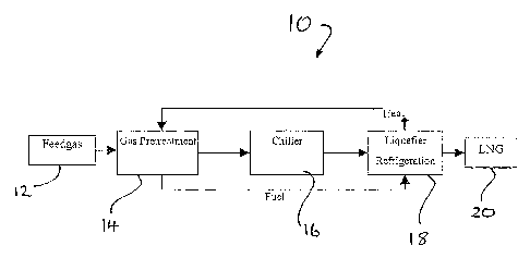
In Figure 1 there is shown a process 10 for the production of liquefied
natural gas
in accordance with the present invention. The process 10' broadly comprises
passing a natural gas feed gas 12 to a gas pre-treatment step 14, after which
the
gas stream is passed to a chiller 16. The chiller 16 cools the gas stream to
at
about -50°C prior to the gas stream passing to a liquefaction stage 18,
finally
producing a liquefied natural gas ("LNG") product 20.
As shown in Figure 1; waste heat from the liquefaction stage 18 is utilised by
both
the chiller 16 and the pre-treatment step 14.
In Figure 2 there is shown the process 10 in greater detail than that of
Figure 1.
The natural gas stream 12 is subjected to a pre-treatment step 14 comprising
an
amine package 22 and a dehydration package 24. The amine package 22 and
the dehydration package 24 remove carbon dioxide and water from the natural
gas stream 12 respectively. Broadly speaking, the pre-treatment step 14 is
required to remove components in the natural gas stream 12 that would
otherwise
freeze at cryogenic temperatures experienced in the liquefaction step 18. The
pre-treatment step 14 normally requires the natural gas stream 12 to be heated
to
CA 02512921 2005-07-08
WO 2004/065869 PCT/AU2003/001623
-7-
about 50°C. As such, this step demands more cooling and more energy to
ultimately reach liquefaction temperature in the subsequent liquefaction step
18.
The liquefaction step 18 comprises at least the majority of a liquefaction
package
26 shown in Figure 2, the liquefaction package 26 comprising a main cryogenic
heat exchanger 28 and one or more expander compressors 30 together with a
refrigeration cycle 32. The refrigeration cycle 32 further comprises one or
more
refrigerant compressor packages 34.
The liquefaction package 18 provides LNG that is passed to one or more LNG
tanks 36 via an LNG separator 39.
The sweet dry natural gas produced by the pre-treatment step 14 passes through
the heat exchanger 28 and an expansion valve 38, where it is cooled to around
-150°C and liquefied prior to passing to the LNG tanks 36. The LNG
separator
produces a small volume of flash gas 39 that is used as make-up gas for the
refrigeration cycle 32, as a regeneration gas 40 and finally as a fuel gas 41
for the
compressor drives 34.
The refrigeration cycle 32 comprises a multi-stage compression, air or water
cooling and expander cycle, with most refrigeration produced by isentropic
expansion of a recycle stream. Power from gas expansion is recovered in a
turbo
expander-compressor and the refrigerant is further compressed in the main gas
engine or turbine driven booster compressors. Warm refrigerant is precooled by
cold refrigerant gas prior to entering the expander so that the required
cryogenic
temperature in the heat exchanger 28 can be achieved.
The chiller 16 is provided in-line between, or upstream of, the pre-treatment
step
14 and the liquefaction package 18. The chilling step 16 may be achieved by
either of a lithium bromide absorption chiller, cooling the natural gas stream
to
about 10°C, or an ammonia absorption chiller, cooling the natural gas
to about -
50°C, or may be a combination of these methods. This chilling of the
natural gas
stream prior to the heat exchanger 28 reduces significantly the load on the
CA 02512921 2005-07-08
WO 2004/065869 PCT/AU2003/001623
_g_
liquefier/refrigeration plant by, in the experience of the applicants, as much
as
50% compared with the prior art.
The chiller step 16 utilises waste heat 42, comprising hot jacket water and/or
hot
exhaust gases, from the main gas engine compressor drives 34. This heating
system may also be used to regenerate the amine and/or preheat the natural gas
stream prior to entering membranes and/or heat regeneration gas required for
the
molecular sieves of the dehydration package 24. Hot dry refrigerant gas from
the
compressor discharge may also be used to regenerate the molecular sieves of
the
dehydration package 24, prior to that same gas being used as fuel for the
compressor drives 34.
Additional heat may be utilised in the chiller step 16, such as may be
available as
waste heat from other prime movers for example those used for power
generation, heat from compression from the burning of flare or other waste
gases
or liquids, solar power and the like.
It is also to be understood that, dependent upon the composition of the
natural
gas stream 12, another benefit of the process 10 of the present invention is
that
the chilling step 16 may condense some components, including heavy
hydrocarbons, LPG's, water, hydrogen sulphide and/or carbon dioxide. These
condensed components can either be a useful product stream or may assist in
the
pre-treatment process itself. Additionally, the flash gas 39 from the LNG
separator 37 is high in nitrogen, thereby improving the heating value of the
LNG
product 20. Further, the flash gas 39 is bone dry making it especially
suitable for
regeneration gas 40 and making it especially suitable as fuel gas 41 in the
compressor drives 34 due to its high methane number.
In Figure 3 there is shown a pressure enthalpy diagram for the process 10 of
the
present invention utilising an ammonia absorption chiller cooling the natural
gas
stream to about -50°C, followed by an expander or "JT" valve 38, as
shown in
Figure 2, to further pre-cool the natural gas stream. It is envisaged that a
compressor, for example a vacuum compressor (not shown), may also be added
to the ammonia circuit to further pre-cool the natural gas.
CA 02512921 2005-07-08
WO 2004/065869 PCT/AU2003/001623
_g_
In Figure 4 there is shown a graph of temperature vs enthalpy from the heat
exchanger 28 demonstrating the significant reduction in cooling load on the
heat
exchanger as a result of the presence of the absorption chiller 16 which has
cooled the natural gas stream to about -50°C.
It is envisaged that more than a single chiller step 16 may be utilised. The
or
each chiller step 16 may additionally be driven by sources of heat other than
the
refrigerant compressor packages described hereinabove.
It is further envisaged that the or each chiller step 16 may utilise fluids
other than
the ammonia and lithium bromide described hereinabove.
In Figure 5 there is shown a process 100 for the production of LNG in
accordance
with a second embodiment of the present invention. The process 100 is
substantially similar to the process 10 described hereinabove and like
numerals
denote like parts and steps.
Importantly, a number of chillers 102 are provided in the process stream, each
being driven by waste heat from the refrigeration cycle 32. The chillers 102
are
placed within the gas pre-treatment step 14 directly after each of carbon
dioxide
removal and drying, and immediately prior to the heat exchanger 28 of the
refrigeration cycle 32. As noted previously, this staged chilling of the
natural gas
stream 12 allows selective condensation and removal of various components
thereof. Within the refrigeration cycle 32 a chiller 102 is used to chill
mixed
refrigerant.
The processes 10 and 100 for the production of LNG each utilise waste heat
from
the refrigeration cycle to generate heat or cold as required, thereby
increasing the
efficiency of the LNG production .process when compared with prior art
processes.
For example, prior art LNG processes lose energy by way of waste heat to
atmosphere. The present invention utilises waste heat to chill the natural gas
andlor refrigerant, thereby improving the efficiency of the process, reducing
capital and operating costs, reducing greenhouse gas emissions and simplifying
CA 02512921 2005-07-08
WO 2004/065869 PCT/AU2003/001623
-10-
the process. Alternatively, a similar efficiency to that of the prior art
processes
may be achieved at a lower capital cost.
It is envisaged that the process of the present invention may be applied
broadly to
refrigeration processes, including those used in air separation plants and LPG
extraction processes, thereby providing similar benefits with regard to
utilisation of
waste heat. Each of these processes require refrigeration and waste heat can
again be utilised to chill the stream, thereby improving efficiency and
reducing
costs.
It is further envisaged that the refrigeration process described above may be
used
to refurbish existing inefficient LNG or air separation plants.
Modifications and variations such as would be apparent to the skilled
addressee
are considered for within the scope of the present invention.