Note : Les descriptions sont présentées dans la langue officielle dans laquelle elles ont été soumises.
CA 02513070 2005-07-11
WO 2004/063310 PCT/US2004/000057
ADVANCED GAS INJECTION METHOD AND
APPARATUS LIQUID HYDROCARBON RECOVERY COMPLEX
FIELD OF INVENTION
The present invention relates to the process of improving and increasing
liquid
hydrocarbon recovery from an oil bearing reservoir by combining the effects of
reservoir pressure increase and oil mobility increase through injection of
natural gas
or another miscible gas into the oil reservoir and injection of high-pressure
gas into
the gas cap above the liquid zone. injection into the oil zone would be
facilitated by
use of horizontal borehole(s) or deep, high permeability, jet-type
perforations from
the main well bore. The advantages of the higher pressure and more mobile oil
would
be realized with a new production scheme utilizing a float-control valve
system on the
lower end of the production tubing which recognizes the difference between
producible liquid hydrocarbons and gas, the latter which is desirable to
retain
downhole for automatic re-injection into the gas cap. Periodic reversal of the
proposed invention-well system into production wells, and vice versa, is
proposed for
efficierit drainage of the surrounding oil reservoir.
The High-Pressure Bottomhole Liquid Injector and Fluid Recovery Complex,
hereafter called HPI invention addition (filed July 5, 2002, U.S. PTO
N° 60~3935~ 5)
relates to producing, offshore or onshore, excessively high-pressure
reservoirs by
producing liquid-only inflow at a high rate through the production tubing
while
1
CA 02513070 2005-07-11
WO 2004/063310 PCT/US2004/000057
maintaining the natural gas for its valuable liquid hydrocarbon recovery
benefits
within the reservoir, in the gas cap and in solution within the oil. The
invention also
relates to methods for recovering liquid hydrocarbons in shut-in wellbore-
reservoir
scenarios at new high-pressure levels to produce onto the surface while
continuously
maintaining pressure at levels never before produced at. These high pressure
levels
could be in primary high-pressure reservoirs or after continued high-pressure
injection
into the reservoir's gas cap and/or oil zone. It is shown and claimed that
producing
under such high pressures maintained in the reservoir's gas cap and/or oil
zone and
adjacent wellbore will recover liquid hydrocarbons to maximum levels of
recovery
unable to be reached by prior art systems.
BACKGROUND OF THE INVENTION
The various processes used or proposed by the industry are described in U.S.
Patent 5,778,977, Bowzer et al, July 14, 1998. These include established
industry
practices of: 1 ) injecting gas into the gas cap to retain or increase
reservoir pressure,
including the added benefit of encouraging gravity drainage of oil liquids
retained in
rock volumes depleted of primary mobile oil liquids; 2) application of oil-
miscible
gases, such as C02 or methane, above reservoir oil liquids and thus increase
their
mobility within reservoir pore spaces or fractured systems; 3) intermittent
injection
of gas and water, and even foam; 4) injection of COZ into vertically fractured
reservoirs; 5) injection of a coolant to thereby increase the miscibility of
C02 in
crudes; 6) determination of the critical properties of various crude
components to
achieve first-contact miscibility. Principal problems discussed include the
likelihood
2
CA 02513070 2005-07-11
WO 2004/063310 PCT/US2004/000057
of injecting gas breakthrough back to the producing wells) instead of creation
of an
effective flood front to drive the more mobile crudes toward lower pressure
producing zones.
The Bowzer Patent further describes an improved process of recovering oil
from an oil-bearing formation having a natural fractured network with vertical
communication, and wherein gravity drainage is the primary means of recovery.
COZ is
concentrated in a displacing slug at the gas-liquid hydrocarbon contact and
the slug is
displaced downwardly to help move oil liquids toward a production well(s). A
chase
gas with a density lower than COZ (high percentage of nitrogen) is used to
propagate
the COZ downwardly. Also, nitrogen is used by the Mexican national oil company
Pemex as a reservoir gas-cap expansion and oil re-pressuring mechanism in its
giant
Cantaretl Complex offshore operation in the Bay of Campeche, Gulf of Mexico.
The HPI invention discloses a downhole oil liquid injector to produce liquid
hydrocarbons and/or waters under extremely high pressure. The new, high-
pressure
bottomhole oil liquid injector HPI, together with a liquid column back-
pressure valve
invention LC-BPV and/or with an addition entitled extended float system EFS,
described later, is especially designed and invented to produce extremely high-
pressure applications as shown in the gas injection complex GIC filed January
9,
2002, with U.S. PTO 60/346311. The HPI with the Extended Float System
invention is
also meant to produce other high-pressure scenarios other than those disclosed
in this
present invention.
3
CA 02513070 2005-07-11
WO 2004/063310 PCT/US2004/000057
The present invention provides nevi and novel injection, production, and
recovery systems, and methods not seen in the prior art, and never before
known or
used in the world oil and gas industry. These important advanced methods and .
techniques for increasing ultimate recovery of liquid hydrocarbon reserves,
are here
after disclosed.
SUMMARY OF THE INVENTION
The basic production system proposed herein is described in U.S. Patents US
6,089,322 July 18, 2000, US 6,237,691 B1 May 29, 2001, US 6,325,152 B1 Dec. 4,
2001, and US 6,22,791 B2 September 23, 2003 with international application
number
PCT/US97/21801 .entitled "Method and Apparatus for Increasing Fluid Recovery
frorn a
Subterranean Forrraation", and succeeding divisional applications, which
describe an
downhole oil liquid injector (DOLI) and several new applications in various
types of
oil and gas producing scenarios. These production systems can be used in
certain
limited production scenarios, while entirety new high pressure production
configurations will be used to produce the GIC when the hydrocarbon reservoir
injection welts are converted to production wells. Further improvements in the
DOLI
system are described herein to produce special downhole liquid-gas definition
at high
pressures and selection effects described.
Because of the importance of the major objects of the present invention, see
"Statement of the Object of the Invention", which are concerned with
recovering vast
amounts or presently unrecoverable liquid hydrocarbon reserves to become
recoverable with this invention and, further, because the present invention's
liquid
4
CA 02513070 2005-07-11
WO 2004/063310 PCT/US2004/000057
hydrocarbon recovery processes have various phases, this section is given to
also help
explain a full disclosure of the present invention, to better understand the
section
entitled "Detailed Description of the Invention".
The present invention discloses systems and methods: (1 ) to reenergize
hydrocarbon reservoirs that are losing their original natural gas pressures
and gas
energy, particularly in solution within the oil as well as in the overlying
gas cap in
defined reservoirs in producing areas or fields by principally returning
solution gas to
the oil and, secondly, gas to the gas cap. (2) To reenergize hydrocarbon
reservoirs
that have lost critically valuable solution gas in the crude oil, by returning
solution
gas, energy and pressure to the in-place crude oil and, secondly, gas to. the
gas cap,
in fields that are now anywhere approaching marginal or considered to be
marginal,
thereby transforming unrecoverable crude oil to recoverable. (3) To newly, and
additionally energize, thereby maximally increasing crude oil mobility, gas
energy and
pressure in various primary hydrocarbon reservoirs that contain high, average,
medium, and especially lower gravity (heavier) crude oils, again by
pressurizing and
energizing, adding critically valuable solution gas, pressure, energy and
mobility to
the in-place crude oil considerably decreasing its viscosity, capillarity and
adhesiveness, as well as increasing the pressure in the overlying gas cap. In
order to
do this, the gas injection re-pressuring system will target an entire
hydrocarbon
reservoir or chosen sections of that same reservoir in synchronized patterns.
In all the foregoing gas injection applications the present invention provides
that, the critically valuable return of solution gas, pressure, energy and
mobility to
CA 02513070 2005-07-11
WO 2004/063310 PCT/US2004/000057
the in-place crude oil and free gas pressure and energy drive to the gas cap
is
maintained and locked-in in the entire hydrocarbon reservoir during the
complete
production and recovery process of the injected into in-place liquid
hydrocarbons.
The present invention also provides that, thus, after the gas injection
period,
during the extensive liquid hydrocarbon production and recovery period, highly
valuable re-injected solution gas will continue to remain in solution within
the total
in-place injected oil, where it has re-entered solution within that crude oil
under a
predetermined injection pressure, which is maintained, until it has been fully
recovered, completely out of the hydrocarbon formation rock into the
production
tubing string on towards the surface. After leaving the formation rock
producing
liquid hydrocarbons first enter the high pressure bottomhole liquid injector
opening
its extended float system and its production valve mechanism, where the then
producing crude oil filled with solution gas senses an abrupt pressure drop,
and only
then solution gas can break out of solution where it flows the valuable liquid
hydrocarbon crude oil through the production tubing string on towards the
surface
separating facilities.
During the gas injection process, the surface compressor, the surface wellhead
casing gas control valve with its surface pressure gauge, and an optimally set
downhole injection-production packer, all contribute to holding and
maintaining this
required high pressure on the entire chosen hydrocarbon reservoir. After the
gas
injection process this critically required predetermined high pressure must be
continually held and maintained on the entire liquid hydrocarbon reservoir.
6
CA 02513070 2005-07-11
WO 2004/063310 PCT/US2004/000057
The present invention provides that during the extensive liquid and gaseous
hydrocarbon production and recovery process this overhead high pressure is
operated
and controlled from two basic control points; the surface wellhead casing
annulus
control valve with its surface pressure gauge, and the preset downhole
production
packer with its pressure relief gas lift valve operated vent tube. The surface
wellhead casing valve with its pressure gauge, cuts back or completely closes
off gas
flow from the casing wellbore annulus, depending upon the type of production
scenario and reservoir. While the production packer when used relieves gas
pressure
into the upper wellbore annulus above the liquid hydrocarbon crude oil zone
where it
has been preset. .
The initial and principal gas injection process is done in the following
manner.
Using a chosen "source gas" SG, the injection gas will be injected through the
casing
head annulus which communicates directly to the open horizontally drilled or
perforated gas zone via the casing annulus. Here, any variety of chosen gases
can be
used, such as, but not limited to, natural gas, CO2, or nitrogen (it should be
noted
that many fields are already using COZ or nitrogen). Multi-zone gas caps can
be
injected into individually. The gas cap injection process works to benefit the
following oil zone injection process and helps recovery by added gas cap
pressure.
The most critically important gas injection process is done through the
central
tubing injection string that will go through the packer which is located
directly below
the gas cap at the top of the liquid hydrocarbon (oil) zone. A bridge plug
optionally
can be used at the bottom of the permeable oil zone in order to seal off the
area
7
CA 02513070 2005-07-11
WO 2004/063310 PCT/US2004/000057
being injected into, whether horizontal boreholes or perforations. Here, a
second
source gas SG2, is pressurized at the surface by a compressor assisted
optionally with
temperature control so that the SG2 will enter the liquid hydrocarbon zone as
a
compressed, pressurized gas, entering and going into solution with the in-
place crude
oil at an optimum injection pressure. Here, it is described that the oil zone
will be
horizontally drilled optionally with deep jet perforations. Here, the
horizontal
borehole(s) can be one or more; however, the vertical wellbore can also be
just
perforated in certain configurations/wells. High performance, deeply
penetrating jet
perforations are available to communicate beyond the wellbore(s) through
cement
sheaths and the skin or permeability-damaged zone. The purpose of the .deeper
jet
perforations is to allow the injected, pressurized gas to "permeate" as deeply
as
possible into the oil in the oil zone. If multiple oil zones exist that are
separated by
non-permeable barriers, the system described can be applied sequentially to
individual oil zones.
Natural or miscible gas that is chosen to be compatible with the crude oil in
its
reservoir is injected directly into the pre-indicated crude oil zone, through
its
horizontal boreholes or perforations. This injected gas, at an optimum given
pressure
level enters solution with the crude oil it comes into contact with. When the
crude oil
zone, under an optimum injection pressure reaches an optimum gas saturation
level,
with the injected gas having entered into solution within the crude oil
through the
permeable formation, the critically important production and recovery process
will be
ready. The foregoing, novel, process of injecting gas under pressure into the
crude
8
CA 02513070 2005-07-11
WO 2004/063310 PCT/US2004/000057
oil within its natural formation and maintaining that pressure throughout the
reservoir
and its producing wellbores entire production and recovery life is claimed in
the
present invention as a new and novel process which overcomes serious
limitations the
prior art cannot.
The following liquid hydrocarbon production and recovery process allows re-
energized crude oil zones with newly injected solution gas, together with the
present
solution gas, if any within the in-place crude oil to be recovered and
produced under
pressure, thereby not losing the crude oil's new life's mobility. Recovering
and
producing under pressure prevents solution gas and pressure from breaking out
and
escaping. Producing under pressure recovers the total in-place crude. oil
injected
with gas. The injection process and production process work together as a
complete
recovery process. Therefore, the novel advantages of the injection process and
the
production phase process are claimed and overcome gas injection and liquid
hydrocarbon production and total ultimate recovery limitations that prior art
cannot.
One major problem with producing liquid-only inflow under high pressure
applications, as needed in the above application, is that excessively high
bottomhole
pressure will prevent the injector valve from opening. The HPI invention
provides a
workable solution to this excessive high pressure problem. An example is a
reservoir
that must maintain, in the reservoir and wellbore, approximately 5,500 psi
bellow or
above during its production and recovery from wellbore to surface. The present
invention is designed to produce liquid hydrocarbons while maintaining the
5,500 psi
or above at the oil intake level at the bottom of the wellbore. The double-
valve
9
CA 02513070 2005-07-11
WO 2004/063310 PCT/US2004/000057
mechanism, which is designed to open at lesser pressures, will not open due to
a very
high-pressure seal. In other words, a 316' pilot tip and seat as designed in
the prior
art, that opens to relieve lesser pressures in order to dislodge the main tip
off tts ~~~~6'
port seat cannot dislodge with 5,500 psi opposing a partial vacuum being drawn
by a
pumping system or even at an atmospheric pressure tubing string.
THE EXTENDED FLOAT SYSTEM
The present invention provides a specially lengthened float to the Downhole
Oil
Liquid Injector DOLI as seen in figure 3, 4, and 7, as an absolute solution
having no
high pressure and related well depth limitations for the GIC high pressure
reservoir
wellbore operating system. The float is open at the top and closed at .the
bottom.
The closed bottom is opened with a hole to receive a valve stem that operates
the
DOLI valve. The float device can be lengthened to various lengths by
connecting
light-weight float material collars threaded to receive reinforced threaded
float ends.
Collar connections can be made up inside float in order to maintain float's
restricted
outside diameter i.e., a float in designated lengths of approximately 20 feet
to 30
feet can be connected by threaded collars and assembled as the tool is lowered
into
the wellbore at the wellhead. A lengthened outside jacket, also with threaded
collars, is required for the DOLI, which likewise can be assembled first as
the tool
enters the wellbore, being made up at the wellhead. The double valve will
remain in
the lower part of the float with its discharge line leading to the injector
head, the
injector head being the production tubing connection. The distinct advantage
of a
lengthened float is its added weight to open the 3/~6' pilot valve at very
high
CA 02513070 2005-07-11
WO 2004/063310 PCT/US2004/000057
pressures. An example: a 3/~6' pilot valve will open at 1,000 psi at an excess
float
weight of 27.6 pounds. Therefore, a 3/~6' pilot valve will open at 5,500 psi
bottomhole pressure with an excess weight of 151.8 pounds created by an
extended
float. Therefore, the lengthened float, in pre-calculated lengths will open
the pilot
valve at 5,500 psi bottomhole pressure. The present invention proposes to have
the
EFS as short in length as possible, in order to allow the injector's
perforated/screened
liquid production section inlet to be as tow as possible in relation to the
newly high
pressured oil production zone. Therefore, some typical installation dimensions
are as
follows: in a 5 'h" OD casing a 16 gauge 2 'h" OD steel float inside a 4" OD
injector
flush joint jacket housing will require 98' of EFS to open the injector pilot
valve. In 6
5/8" OD casing, a 5" OD injector flush joint jacket with a 3 '/2" OD 14 gauge
steel
float would require 60' of EFS. in 7' casing, a 5 'h" OD injector flush joint
jacket
would allow a 4" OD float of 14 gauge steel that would require 53' of EFS.
This novel and operative extended float system will discharge high pressure
oil
to a sudden drop in pressure in the tubing where a volume of gas breaks out of
solution and flows crude oil towards the surface. The oil flow can be aided by
fluid-
operated gas lift valves. Above the lower gas lift valves on the tubing is
located a
Venturi tube device, which by the velocity flow through its inner throat
creates a
more efficient gas-liquid mixture piston sweeping action to help drive the
flowing
liquid column to the surface. As the flowing liquid hydrocarbon column is
lifted in
deeper wells, additional gas lift valves without Venturi tubes are spaced at
higher
levels and activated by the tubing pressure which flows liquids using high-
pressure
11
CA 02513070 2005-07-11
WO 2004/063310 PCT/US2004/000057
annulus gas onto the surface to the well's tubing flow surface receiving
system,
typically a surface separator. The inventor whom presently manufactures the
DOLI as
seen in prior art, makes claim to the practicality and operativeness of the
new and
novel EFS invention.
The extended float system EFS will produce all depth wells without any depth
or pressure limitations. The unique and novel advantages of this invention are
claimed and overcome all extreme high pressure limitations and related extreme
high
volume and depth lift limitations that the prior art cannot.
METHODS TO IMPROVE OR ASSIST THE DOLI OPERATION
Because it is impractical to use an injector valve's pilot valve smaller than
3/~6'
diameter pilot port, two other application procedures are proposed. If not
already
existing in subject producing welts, these two application procedures are: to
drill a
sufficiently deep rathole in the well and/or to ream out an open hole and
rathole in
order to allow larger dimension DOLIs to operate, where feasible. A larger
dimension
injector with a larger float mechanism will help open a larger pilot valve
with a larger
main port against higher-pressure scenario extremes with the aid of the EFS
and/or
LC-BPV, the EFS being the preferable scenario. Also, this invention proposes
to
specially drill and complete new wells in order to accommodate an extra large
dimension DOLI system.
A DESCRIPTION OF THE GAS CAP REPRESSURING
The purpose of the gas cap re-pressuring, if it is an older gas zone or newly
pressuring, if it is an original new zone is to increase the pressure on the
gas cap to a
12
CA 02513070 2005-07-11
WO 2004/063310 PCT/US2004/000057
chosen, high optimum pressure. Some of the injection gas here may go into
solution
with the oil bellow the gas cap.
A DESCRIPTION OF THE LIQUID HYDROCARBON (OIL) ZONE REPRESSURING
A gas is chosen that is identical or compatible with the reservoir liquid
hydrocarbons. The purpose of the oil zone re-pressuring is several fold: (1 )
To
permeate the oil with pressurized gas which will readily go into solution or
re-enter
solution with the oil under a designated pressure. Such pressure is created to
the
required optimum pressure by the surface compressor, which compresses
pressurized
gas into the oil zone. (2) As pressurized gas goes into solution within the
crude oil,
solution gas pressure returns to the oil. (3) As pressurized gas goes into
solution
within the oil, increasing the oil's mobility, and its propulsive force, it
decreases its
density, viscosity, capilarity, and adhesiveness, making it lighter by lighter
density
gas going into solution with a heavier density liquid the in-place oil. (4)
The final
result and purpose, being that the combination of the aforementioned benefits
makes
and allows the injected in-place crude oil to migrate more freely and rapidly
as a
newly lighten mobile fluid towards the wellbores, horizontal andlor vertical,
to be
produced at a higher rate while efficiently enhancing total in-place oil
ultimate
recovery.
The pressured light oil buildup starts around the perimeter and slowly
migrates
into other, less energized, oil in the radius around the vertical wellbore and
or
horizontal borehole. This process continues supplying solution gas into the
surrounding oil, continually providing solution gas to the oil as it migrates
outward,
13
CA 02513070 2005-07-11
WO 2004/063310 PCT/US2004/000057
until it reaches saturation points at given higher pressures. This process
tends to
build up as rising, high-pressure injected gas meets gas-saturated oil,
forcing the
pressurized gas to the lower pressure, non-pressurized oil in the outlying
borders.
This high-pressured gas wilt move away from the re-pressured zone around the
wellbore, contacting even more reservoir liquids as banks of saturated crude
form.
GAS INJECTION PERIOD
(See GIC, Fig. 1 )
The gas injection period in chosen areas of the hydrocarbon reservoir into the
gas cap is continuous or intermittent until a desired pressure is reached.
Also,
produced gas breaking out of solution from producing liquid hydrocarbons is re-
injected. It should be noted that the gas cap will communicate throughout the
upper
part of the entire reservoir due to the permeability of the overlying gas cap.
The oil
zone re-pressuring is separate and will periodically cease when the oil zone
reaches
an optimum point to where the oil has both increased maximum mobility through
pressurized gas saturation and is considered to be at the optimum pressure
within the
liquid hydrocarbon zone by injected gas reentering solution within the oil. At
the
ideal point, these injection (into the oil zone) wells will be converted to
production
wells.
When the GIC is injecting into the chosen sections of the reservoir rather
than
the entire reservoir, the sections that were producing will be converted to
oil zone
injection wells and the oil zones sections that were being injected into will
be
converted to producing wells. It should be noted that the injection and
producing
14
CA 02513070 2005-07-11
WO 2004/063310 PCT/US2004/000057
section patterns of the reservoir will be determined by studies of the
reservoir. The
feasibility of the alternative can be studied: to inject into the entire oil
zone section
of the reservoir at one time.
The present invention requires that the entire oil reservoir, both injection
and
production sections, be continually held under pressure from day one
throughout the
production life of that reservoir by improved downhole oil liquid injectors
with the
extended fload system (EFS) at the surface wellhead casing valve, with its
surface
pressure gauge and, or with packer configurations being permanently in place
above
the liquid hydrocarbon production sections. In some production scenarios only
liquid
hydrocarbons wilt be produced, while any gas breaking out of solution from the
producing liquid hydrocarbons will be re-injected back into the reservoir and
or used
to operate surface systems. While in other productions scenarios, natural gas
can be
produced from the upper hydrocarbon reservoir at a controlled rate.
INSTALLING PRODUCTION SYSTEM PRIOR TO HIGH PRESSURE GAS INJECTION INTO
CRUDE OIL ZONES
The present invention will employ oil industry known and provided
equipment and services for its installation into the well. This installation
procedure
will be made prior to high pressure gas injection into the oil zone. First by
killing and
controlling the well with non-damaging liquid fill, then the DOLI, with the
EFS on the
injection/production tubing string is lowered into the well to its
predetermined
CA 02513070 2005-07-11
WO 2004/063310 PCT/US2004/000057
producing position relative to the oil zone. The principal industry provided
components on the tubing string are:
1.- A wireline operated from the surface well head through a pressure sealing
lubricator, opening and closing a pressure sealing sliding sleeve tool on the
tubing string above the DOLI. The sliding sleeve tubing joint is located at
the
predetermined injection into the oil zone area above the DOLI where it is
opened by surface wireline control, for the present invention's high pressure
gas injection procedure from surface through tubing into the opened oil zone.
Once the injection procedure is finished, the pressure sealing sleeve on the
tool is then closed from the surface for the production period.
2.- The combination injection and production packer is supplied by the oil
industry's global companies, such as Baker Oil Tools', Weatherford, and
others.
The to be permanently set packer is on the tubing string above the sliding
sleeve, which will.~be located at the top of the predetermined liquid
hydrocarbon zone area below the gas cap where the to be pressurized oil
zone's annulus is separated and sealed off from the gas cap annulus. This
packer has two functions, to pressure seal the annulus during the injection
procedure, and then later to relief gas build up pressure through its to be
activated pressure relief vent orifice. The vent tube is a gas lift type valve
which will operate on a side pocket mandrel above the packer for 5 '/z", 6
5/8", or 7" casing as shown in figure 9. The gas lift mandrel will contain a
wireline operated dummy valve plug, which is removed and exchanged for the
16
CA 02513070 2005-07-11
WO 2004/063310 PCT/US2004/000057
actual high pressure gas lift type valve by the wireline operating through a
surface pressure control lubricator. The high pressure gas lift type valve is
to
relief gas pressure built up at a predetermined setting over the critical
pressure of approximately 5,500 psi.
3.- Above the packer, on the tubing string are one or more gas lift valve
mandrels which contain, again wire line operated dummy valves which
maintain the high pressure seal during the gas injection process. When it is
time for the production process, these dummy valves are pulled by the wire
line and pre-set pressure gas lift valves are installed by the wire line.
Weatherford and other major gas lift valve companies supply such wireline
operated gas lift valves and service.
AN OPTIONAL INSTALLATION PROCEDURE
In active high pressure wells where the above installation procedure was not
feasible the following oil industry provided installation procedure can be
used.
Once the gas injection process has completed a planned phase in which a
predetermined volume of in-place crude has been solution gas saturated by gas
entering solution with the crude oil under high-pressure, the present
invention's
production system can be installed. In active high pressure wells a principal
objective
of converting to the production scenario is to install the production system
without
killing the well with higher-density liquids, which is impractical at
pressures
exceeding 5,500 psi, and could be detrimental to near-wellbore permeability's.
A high pressure production system installation will use industry-available
pressure-control services and systems for installing the present invention's
downhole
17
CA 02513070 2005-07-11
WO 2004/063310 PCT/US2004/000057
production equipment under excessively high wellbore pressures. Such pressure-
control services are provided by known companies specializing in high pressure
installations, such as Halliburton HW, Cudd Pressure Control, and others. An
installation, under pressure, will entail providing high-pressure equipment on
the
surface wellhead that includes properly sized blowout preventers with dual
hydraulic
snubbing packers that close around the outside diameter of pipe sections to
allow into
and out of the well, pipe movement as the pipe slides along the pressure
seal. When collars or other changes in pipe diameter such as gas lift
mandrels, reach
the sliding seal, the hydraulic packer sliding seal element above the collar
is closed
and the packer seal below the collar is opened to allow passage of the collar.
The
two-packer opening/closing process is then reversed and pipe moving continues.
This
process is called "snubbing" in the oil industry.
The snubbing process can be used to install the present invention's Downhole
Oil Liquid Injector's DOLI closed at the bottom pipe housing containing the
extended
float system and its related internal parts, valve mechanism, 1 " discharge
production
line, and collars being assembled at the surface before actually entering the
snubbing
unit. This snubbing process continues until the DOLI's open perforated pipe
section is
reached. The snubbing unit then uses a specially designed lubricator which is
built to
scale to encase the open perforated pipe section approximately 30' to 38' in
length.
The lubricator is then towered over the perforated pipe section and screwed
into the lower snubbing unit. The top of the lubricator is equipped with a
second set
of snubbing packers, which will operate on the main tubing string, opening and
closing
for tubing collars, gas lift mandrels, and any production packers. With the
top
snubber closed on the tubing joint, the original snubbers can be opened,
allowing
18
CA 02513070 2005-07-11
WO 2004/063310 PCT/US2004/000057
communication of the DOLI to the tubing-casing annulus. Tubing string
installation
then continues for the complete well installation with the snubbing packers.
It should
be noted that a wireline removable plug may optionally be installed directly
above
check valve on top of the DOLI in order to close off the tubing while going
into or out
of the wellbore in order to prevent liquid flow through the DOLI. Such wire
line plugs
are provided by Weatherford and other leading gas lift providers.
THE PRODUCTION WELL SYSTEM
Here it must be clearly explained and emphasized that the entire hydrocarbon
reservoir, its gas cap(s), and liquid hydrocarbon zones) must be maintained
under
required high pressure levels, or shut-in pressure levels, in order to produce
and
recover the newly energized with solution gas and pressure liquid hydrocarbons
within
their given formations. These high pressure levels will be maintained in the
wellbore
and corresponding formations throughout the entire liquid hydrocarbon recovery
process until the total in-place liquid hydrocarbon is recovered from the
entire
reservoir. Only then will the gas cap gas be released and produced in any
substantial
volume.
In order to produce the hydrocarbon reservoir's newly pressured oil zones, the
DOLI is installed on a production tubing string in the deepest part possible
of the
wellbore, or its rathole, when possible, ideally below the oil zone horizontal
borehole
or perforations in order to obtain the maximum drainage/liquid recovery from
that
zone. The DOLI will operate with an EFS as needed, which opens the DOLI's
valve at
the indicated bottomhole pressure. A packer is installed at the pre-calculated
liquid
19
CA 02513070 2005-07-11
WO 2004/063310 PCT/US2004/000057
hydrocarbon (crude oil) reservoir level below the gas cap. The packer will
have a
pressure relief valve discharge tube (PRVD tube). The PRVD tube will be set to
open
in order to relieve pressurized gas buildup in the upper wellbore below the
packer
during the production process, through the packer into the upper reservoir gas
cap
within the wellbore. Any relief gas relieved through the PRVD tube can reenter
the
upper open gas cap in shut-in pressure scenarios. Relieved pressurized gas in
the
upper reservoir will reenter the open gas zone once pressure exceeds gas cap
reservoir pressure. ,
After the oil zone reservoir has been injected into the wells perforations
and/or
through a horizontal borehole or boreholes, pressurized gas, dissolvedlin
solution with
the oil, will gradually accumulate in the borehole radius of the oil zone. The
gas in
solution with oil levels will depend upon the prior period of pressurized .gas
injection.
Injected pressurized gas will tend to surge out in a flooding pattern, subject
to the
reservoir's permeability, thereby seeking non-gas-saturated oil at its levels.
After the injection phase is completed, the well's production process begins.
Any and all liquid hydrocarbon production entering the vertical wellbore will
accumulate into the lesser pressure tubing string. The injector tubing string
to the
surface is the casing annulus liquid draw-down point. Each reservoir,
according to its
given pressure, will maintain a given fluid level within all the wellbores
entering that
reservoir, and, further, that this fluid level is consistent and varies only
with back
pressure on the wellbores. However, when the injector with tubing string to
surface
is present within the wellbores entering that reservoir, then, in effect, a
new
CA 02513070 2005-07-11
WO 2004/063310 PCT/US2004/000057
wellbore is created within the initial back pressured wellbore annulus. In a
well
operating with an EFS, this new injector to tubing string wellbore will be
open to
close to atmospheric pressure (the well's surface separating system) for
flowing heads
of oil up through the EFS as gas breaks out of solution.
AN OPTIONAL GIC PRODUCTION WELL VARIATION
Reference is made to Figs. 1-12 of the following U.S. Patents Granted to
Kelley
et al., US 6,089,322 July 18, 2000, US 6,237,691 B1 May 29, 2001, US 6,325,152
B1
Dec. 4, 2001, and US 6,622,791 B2 Sept. 23, 2003 mentioned under SUMMARY OF
THE
INVENTION, particularly Figs. 4, 5, 6, 7, 9, 10, 11 and 12, but not excluding
Figs. 3,
and 8, for special production scenarios. It should be noted. that in the.
production
period of the re-pressurized/re-energized hydrocarbon reservoir, in the
production
wells, because of packer placement as seen in Figs. 4, 5, 6, 7, 10 and 12,
noted
above, the re-injected gas, both in the gas cap and in the oil zone, would not
escape/dissipate through the production system, as only re-pressurized/re-
energized
liquid hydrocarbons will be produced through the liquid injector on up through
the
artificial lift system in the production tubing on to the surface. f An
exception to this
is when pressurized gas is produced with the oil and then is re-injected back
into the
reservoir injection system. This is noted in the use of Figs. 3, and 8, where
optimally
released gas is re-injected back into the reservoir from the surface
operation. The
extended float system can be applied on these production scenarios where high
pressure prevents the injector valve's opening.
A SOURCE NATURAL GAS INJENCTION SYSTEM
21
CA 02513070 2005-07-11
WO 2004/063310 PCT/US2004/000057
The present invention is applied in primary or middle-aged fields, where high,
average, to lower gravity crude oils are found with substantial gas in place
in the
virgin gas cap. This variation of the invention will be a valuable enhanced
recovery
method in areas where gas flaring is not permitted, or where gas pipelines are
not
available in many U.S. and world oil fields that lack gas handling and
marketing
facilities.
The natural gas found in the gas cap is produced to the surface for the sole
purpose of being compressed by a compressor complex into a pressurized gas to
be
re-injected through a gas repressing center tubing string to pass through one
packer
that is directly above the liquid hydrocarbon (oil) zone. This compressed.
(optionally
temperature controlled) pressurized injection gas is pumped/compressed into
the
mother oil zone, where it finds its own compatible oil to go into solution
with,
thereby adding further solution gas to the in-place oil to increase its
pressure and
mobility for enhanced recovery.
Here the oil zone is opened with a horizontal borehole or boreholes with deep
perforations, or with deep perforations in the vertical wellbore. , The
horizontal
boreholes would be in the optimal part of the oil zone in order to fully
saturate the
oil by gas reentering solution with the oil in the radius around the borehole
during the
injection process. In very thick, massive zones, multi-horizontal boreholes
can be
used at strategic liquid hydrocarbon (oil) levels in the reservoir. Where not
feasible,
deep jet perforations can be used in the vertical wellbore.
22
CA 02513070 2005-07-11
WO 2004/063310 PCT/US2004/000057
If needed, a different outside gas (example: other source natural gas, CO2, or
nitrogen) can be injected into the gas cap to increase its pressure to the
optimum
desired during and/or after drawing its natural gas off for re-pressuring/re-
energizing
its lower liquid hydrocarbon (oil) zone. However, a relatively large volume of
gas cap
gas is not needed in related volume when newly energizing and pressuring the
oil zone
to intensify enhanced recovery. Further, gas pressure should not be notably
lost
during injection into the oil zone, as no substantial gas volume is spent.
Here, all gas
breaking out of solution in produced liquid hydrocarbons during the production
process can be re-injected into the reservoir's gas cap and/or oil zone
through the
surface injection system. The only gas used from the reservoir is to run .the
surface
injection systems, compressors, pumping systems, etc.
IMPROVED DOWNHOLE OIL LIQUID INJECTOR
The Improved Injector (Imp Inj) disclosed is one of the most functionally
important bottomhole (BH) tools for the production of liquid hydrocarbons and
waters
for today's oil and gas industry.
The Imp Inj has two basic functions: (1 ) To allow liquids to enter the
production tubing freely and instantaneously, without any hindrance, as they
enter
the wellbore from the reservoir. (2) To keep out any and all free gas under
all
various pressure conditions. There are four production condition problems that
the
Imp Inj is meant to overcome: pressures, volumes, sands and well dimensions.
There
are certain orifice size restrictions and pressure/volume/sand/well dimension
problems that the Imp Inj will overcome that the prior art wilt not. The Imp
Inj in
23
CA 02513070 2005-07-11
WO 2004/063310 PCT/US2004/000057
today's industry will be producing extremely large volumes of liquids under
very high
BH pressures and in cases with severe influx of very fine formation sands.
THE PRESSURE PROBLEM
When the screen's rib section's slots are plugged with fine formation sand,
excessive high pressure can cause the screen to collapse. Therefore, the
screen must
be built on a collapse-resistant, reinforced perforated pipe base in order to
not
collapse the entire upper part of the injector in excessively high-pressure
wells. All
other high pressure level problems for all depth wells are completely overcome
by the
extended float system (EFS).
THE VOLUME PROBLEM
The screen's rib section slot orifice size openings are restrictive to large
volumes of liquid hydrocarbons and/or waters (LH, W). Ex: The present screen
is
3.75 ft. by 4.5 in. OD and has an open flow area of 39.0 sq. in. per foot. and
has a
flow rate of 750 barrels per day (bpd). For new application in wells that are
producing in the thousands of barrels of LH, W per day, the screen length will
be
increased. Going from the present position, as seen in Fig. 3 in an upper
direction,
whatever screen length required, the top of it with its perforated pipe base
would
make into the Injector's head, i.e., the injector's head would be the
production tubing
and/or pump connection. Ex: If 3.75 ft. of screen equals 750 bpd and a well is
producing 7,500 bpd, then the Imp Inj would need 37.5 ft. of screen section on
24
CA 02513070 2005-07-11
WO 2004/063310 PCT/US2004/000057
perforated pipe. If the screen section goes over the standard tubing pipe 30
foot
length, then screw flush couplings will be used.
AN IMPROVED DESIGN OF THE INJECTOR SCREEN FOR THE SAND PROBLEM
The injector screen will be used with the open slot rib section in a vertical
position. A vertical screen is shown on the injector at the oil/liquid inlet
level. The
vertical screen provides more effective sand control, the vertical screen
configuration
prevents the liquid hydrocarbon/water contact that may carry fine formation
sand
from entering the screen rib section at the same level. The vertical slots
allow the
sands more space to settle out to the bottom of the wellbore. For more
effective sand
control, screen slots can be sized in 0.001" increments to retain formation
sand. This
new vertical design is not seen in the prior art.
WELL DIMENSION PROBLEMS
The present invention also discloses an improved injector housing (not
illustrated in figure drawings) by providing a thin shroud made of thin steel
or
synthetic material, rather than the standard, thicker pipe material. The
shrouded
protective cover would be open at the top and closed or open at the bottom
with a
vertical screen inside thin, perforated shroud bottom when opened. The
improved
shrouded design is particularly for wells with little or no sand influx, which
is not
uncommon in many oil fields. If needed, a vertical sand screen perforated pipe
head
may also be used on the upper injector's oil and gas intake to keep out well
debris.
CA 02513070 2005-07-11
WO 2004/063310 PCT/US2004/000057
This thinner shrouded body to the injector would allow injector installation
in smaller
diameter wells which is common in many oil fields where its internal
components can
be changed proportionately and herein is claimed as a needed improvement to
the
invention.
STATEMENT OF THE OBJECT OF THE INVENTION
The present invention has several objects:
1. To reactivate unrecoverable crude oil to become recoverable, such oil
having
Lost its solution gas to flowing the oil with gas methods. The U.S. and the
world have vast amounts of this unrecoverable oil still in place,. sometimes
as high as 80% of the original oil is left in place, dormant without solution
gas.
2. To recover the total in-place liquid hydrocarbons in reservoirs that are
still
producing liquid hydrocarbons with gas in solution.
3. To enhance the recovery process of low gravity heavy crude oil. A large
percentage of the U.S. and world oil supply is low gravity or heavy crude
oil.
4. To generally enhance the recovery of all gravity crude oils by adding
solution
gas and pressure to the in-place oil.
It should be noted that the production system in the above technology
eliminates flowing oil with gas, as it allows only liquid hydrocarbon recovery
while
26
CA 02513070 2005-07-11
WO 2004/063310 PCT/US2004/000057
retaining gas and pressure in the hydrocarbon reservoir. This production
system,
combined with injecting solution gas and pressure to the in-place crude oil,
is
considered to be a major liquid and gaseous hydrocarbon recovery advance for
the
U.S. and world oil industry, as it will recover the majority of the U.S.' and
the world's
in-place liquid hydrocarbons while keeping the reservoir's natural gas within
its
natural gas cap, stored for future production methods. Thus, the foregoing
objects
with their U.S. and global benefits are claimed and overcome all prior art,
U.S. and
world-wide.
Brief Description of the Drawings
Figure 1 illustrates the concept of compressing a miscible gas to high
pressure
and injecting it directly into a downhole liquid hydrocarbon bearing reservoir
through
a tubing string, both through perforations in the main casing string and/or a
horizontal wellbore extending laterally into the liquid hydrocarbon bearing
zone.
Individually and above a packer isolating the liquid hydrocarbon zone,
compressed
high pressure gas is injected into the tubing-casing annulus and into a
horizontal
borehole and/or perforations into the gas cap overlying the liquid hydrocarbon
zone.
Arrows indicate miscible gas directly contacting liquid hydrocarbons and gas
in the gas
cap contacting a large area of the liquid hydrocarbon zone.
Figure 2 illustrates a variation of high-pressure gas injection into the
liquid-
hydrocarbon bearing reservoir in which gas cap gas flows to a surface
compressor
27
CA 02513070 2005-07-11
WO 2004/063310 PCT/US2004/000057
through the tubing-casing annulus, isolated by a packer and is re-injected
through the
tubing string of the same well directly into its own compatible liquid-
hydrocarbon
zone.
Figure 3 illustrates the components and operating principles of the Downhole
Liquid Injector with its float-operated shutoff valve system permanently
immersed in
a liquid contained within the outer housing, and the sand screen featuring
vertical
slots around an internal ported base pipe.
Figure 4 illustrates principal components of the extended float system in
which
float length is extended as much as four or five times that of conventional
systems.
The sand screen with its ported base pipe is shown elongated also by addition
of one
or more sections.
Figure 5 illustrates a second liquid-hydrocarbon zone producing system in
which
an extended-length float system operates under high bottomhole pressure to
supply
partial columns or slugs of liquids into the production tubing strung, through
which
they are lifted to surface using gas lift valves connected to the tubing-
casing annulus,
and in cooperation with a new venturi jet system.
Figure 6 illustrates a system of producing a well under high bottomhole
pressures utilizing a Downhole Liquid Injector system that allows only
reservoir liquids
28
CA 02513070 2005-07-11
WO 2004/063310 PCT/US2004/000057
to flow into the tubing string. Shown on the tubing string is a packer
directly below
the gas cap with a vent tube and gas pressure relief valve into the gas cap.
Within
the tubing, a full column of reservoir fluid flows through a surface back
pressure
valve.
Figure 7 illustrates schematically an improved Downhole Liquid Injector with
an
extended float system as it would look in the wellbore's rat hole below the
open-to-
liquid-hydrocarbon (perforated) zone, to better appreciated its extended
length in
the wellbore. Lengths of the improved liquid injector can vary from 50 ft. up
to and
over 230 ft. for high volume, excessively high pressure wells.
Figure ~ illustrates a well under high pressure miscible gas injection into
both
the gas cap and the liquid hydrocarbon zone from surface compressors, in this
case
through deep perforations in the vertical wellbore and through horizontal
boreholes
extending deep into the formation. The Downhole Liquid Injector (DOLI) is run
on the
tubing string with a permanent check valve directly above it and a wireline
operated
sliding sleeve valve above the check valve, which is opened and closed by
wireline to
allow either high pressure gas injection through the tubing into the formation
through
the lower tubing-casing annulus, or production of formation liquids up the
closed
tubing, respectively, without pulling the tubing string. For the packer vent
tube
relief valve and the one or more gas lift valves above the packer, wireline
installed
and removed dummy valve plugs are set into the mandrels for the injection
process,
29
CA 02513070 2005-07-11
WO 2004/063310 PCT/US2004/000057
as shown. This figure relates to Figure 1, of which the previous description
discusses
the injection process.
Figure 9 illustrates the production scenario following high pressure gas
injection, with the downhole liquid injector, check valve, sliding sleeve
tubing tool,
packer with vent tube, and upper gas lift valves) already in place, as per
Figure 8,
and relating to Figure 5. To prepare for production, as shown, a wireline
operated
through a surface lubricator will be used to pull the dummy valves and install
the gas
lift valves, and gas lift type vent tube pressure releif valve shown. It will
also shift
the sliding sleeve valve to the close position. This will make the well system
ready to
flow saturated liquid hydrocarbons through the downhole injector while
preventing
free gas entry into the tubing, where gas pressure build up is relieved up the
annulus
by the packer and the vent tube arrangement. In figure 8 and 9, a bridge plug
is
shown below the DOLI, which wilt isolate any extensive rat hole or lower
formations
from the selected zone gas injection/production process.
Detailed Description of the Invention
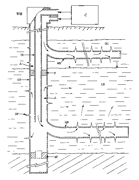
High Pressure Gas Injection into Liquid Hydrocarbon Reservoir Formations
Figure 1 schematically depicts principal features of the present invention in
which liquid hydrocarbons within the downhole liquid hydrocarbons LH
reservoir,
which can be in various stages of crude oil recovery. The present invention
process is
CA 02513070 2005-07-11
WO 2004/063310 PCT/US2004/000057
designed for crude oils of all gravities and is particularly vitally important
for
increasing recovery of all primary through marginal lower gravity heavy crude
oils, of
which there are vast reserve deposits in North America (U.S., Canada and
Mexico),
South America (Venezuela) and throughout the oil-producing world. This
invented gas
solution and pressure reentry process is also extremely vital for converting
unrecoverable oil reserves to become recoverable that have been depleted from
their
original state of being saturated with natural gas that was originally in
solution within
the crude oil under their original high virgin reservoir pressure. These oil
reserves
are now marginal with the majority of the original in-place oil unrecoverable
or
becoming unrecoverable, and a great part of the world's reserves are presently
or in
the stages of becoming marginal. Therefore the present invention injection
process
is used for all various types of crude oil gravities in production stages of
primary (new
oil) through to marginal (old, becoming dormant oil). These in-place liquid
hydrocarbons LH (crudes) are injected into with high pressure natural gas from
a
surface compressor C that is compatible with their oil types, preferably
natural gas
produced from their same, or similar, reservoir field areas. Therefore, the
invention
process's principal purpose is to reenergize with solution gas and pressure
liquid
hydrocarbon LH zones with high pressure natural gas where the crude is
contacted
directly with miscible natural gas pressurized by surface compression from
compressor
C and injected into the liquid hydrocarbon LH reservoir through an injection
tubing
string TS isolated from other reservoirs such as the upper gas cap GC and any
deeper
reservoirs by a packer P and bridge plug BP, respectively.
31
CA 02513070 2005-07-11
WO 2004/063310 PCT/US2004/000057
To most efficiently contact liquid hydrocarbons with the miscible natural gas,
combinations of deeply penetrating perforations DP--such as those created by
modern
jet perforators--in the original casing string CS, and/or one or more
horizontal
boreholes HB, with the horizontal borehole's perforated casings directed away
from
the main wellbore in a predetermined direction and pattern to contact as much
liquid
hydrocarbon LH reservoir as possible. Miscible natural gas directed into the
annulus
A around and below the tubing string TS will contact liquid hydrocarbons LH
deep
within the reservoirs as well as those in the near-wellbore area, by continued
compression from compressor C, increasing solution gas and pressure reentry.
Re-
saturation of liquid hydrocarbons LH around the wellbore from which natural
gas is in
the process of breaking out or broke out as a reaction to producing early high
rates at
low wellbore pressures is critical for converting unrecoverable oil to
recoverable
crude oil for total crude oil recovery. Flowing oil with gas practices rapidly
degas
crudes and create channels of released gas into the wellbore which is
increasing the
"marginal oil" problem in hydrocarbon reservoirs throughout all U.S. and world
oil
fields. Early operators saw these problems manifested in increasing gas/oil
ratios and
falling crude production as they blew off reservoir gas in flush production
operations.
Natural gas enters into miscibility with liquid hydrocarbons at extremely high
pressures. This identical injection process is also shown in figure B where
the
production system has been installed prior to the injection process. High
pressure gas
32
CA 02513070 2005-07-11
WO 2004/063310 PCT/US2004/000057
is injected from the surface compressor C through the well head WH down the
tubing
string TS as the high pressure sealing dummy gas lift valves DV and vent tube
dummy
valve DV hold the pressure seal. The closed packer P holds pressure from the
top of
the liquid hydrocarbon LH zone down to where the bridge plug BP holds the
pressure
bellow the liquid hydrocarbon LH zone. Injection gas exits out through the
opened
sliding sleeve's SS ports where the gas is high pressure compressed into the
opened
liquid hydrocarbon LH zone via deep perforations DP andlor horizontal
boreholes HB.
The gas cap GC is also being injected into, from the surface compressor C via
the
casing string CS where dummy gas Lift valves DV on the tubing string TS hold
the
pressure seal as gas is compressed through deep perforations DP and/or
horizontal
boreholes HB into the gas cap GC. Thus the present invention discloses
injection of a
natural gas directly into liquid hydrocarbon LH zones pressurized by surface
compression.
For gas cap re-pressuring, C02 is commonly used, and sometimes nitrogen;
however, in this invention miscible natural gas is preferably used, when
available, for
injection into the liquid hydrocarbon LH reservoir's gas cap GC. Therefore,
natural
gas is preferably used when available through deeply penetrating horizontal
boreholes
HB drilled from the main wellbore and open to the tubing-casing annulus A
above the
packer P. Such a configuration pressures a very large area of the gas cap GC
as the
more friction-free gas moves through the higher permeability away from the
horizontal borehole HB. Gas cap GC injection contacts and re-pressurizes a
large area
of the liquid hydrocarbon LH reservoir to work in conjunction with the
miscible
33
CA 02513070 2005-07-11
WO 2004/063310 PCT/US2004/000057
natural gas injection. It will also act to increase the efficiency of gravity
oil drainage
from within any portion of the gas cap GC above the liquid hydrocarbon zone.
The
miscibility of C02 could be an alternative, or nitrogen with its various
economic and
environmental benefits, when available, where natural gas is not available.
Figure 2 illustrates a claimed benefit of high-pressure natural gas injection
in
which the source of the high pressure miscible natural gas injection is the
natural gas
from the gas cap GC above its own liquid hydrocarbon LH zone and separated by
a
optimally placed packer P on the tubing string TS. The natural gas is produced
from
the liquid hydrocarbon LH reservoir's gas cap GC up through the upper wellbore
annulus A above the packer P into a surface compressor C, which compresses the
natural gas at high pressures into the injection tubing string TS and into
perforations
of the liquid hydrocarbon LH zone in the main casing string CS andlor one or
more
horizontal boreholes HB with deeply penetrating perforations DP. As wilt be
emphasized in other features of the invention, gas is not produced with the
liquid
hydrocarbons, so essentially all gas remains in, or is circulated back into,
the
downhole system into gas cap GC and/or liquid hydrocarbon LH formations to
achieve
optimally increased 'liquid hydrocarbon LH (crude oil and condensate)
recovery.
Improved Downhole Liquid Injector Features and Operation
Figure 3 illustrates the primary components of the improved Downhole Liquid
Injector DOLI disclosed in the present invention as the principal novel
component of
34
CA 02513070 2005-07-11
WO 2004/063310 PCT/US2004/000057
an improved downhole producing system process that will allow the system to
produce liquid hydrocarbons at high pressures and volumes while maintaining
these
high pressures until the liquid hydrocarbons reach the production tubing
having left
the reservoir's formation in order to completely and thoroughly utilize the
newly
increased crude oil mobility, crude pressure and reduced viscosity/density
while
retaining high pressure gases downhole in the gas cap and the liquid
hydrocarbon
reservoir in solution under pressure within the crude oil within the
formation.
The Downhole Liquid Injector DOLI illustrated comprises the following basic
components. (The extended float system EFS, a major component advance,
improving
the Downhole Liquid Injector DOLI's functionality to produce and recover high
pressure re-energized crude oil is described in Figure 4. The extended float
system
EFS and the vertical sand screen filter allow the Downhole Liquid Injector
DOLI to
produce all variable high pressures and volumes.) A float 12 constructed of a
relatively thin steel, ex. 16 gauge, or 14 gauge and 2'/2in., 3 in., or 3'/z
in. in outside
diameter, depending of wellbore and Downhole Liquid Injector DOLI size,
approxiimately 24 ft. long, in conventional downhole injectors. The float 12
operates
within an outer housing 10 of basic carbon steel, typically containing male
threads on
top and bottom for connection of a top collar and a bottom female bull plug 11
with
threads for either a male bull plug or an additional length of tubing for
powdery sand
collection.
The housing 10 will be permanently filled with a liquid level LL such as
treated
brine. The float 12 operates within this liquid, and its buoyancy, i.e.,
whether its
CA 02513070 2005-07-11
WO 2004/063310 PCT/US2004/000057
rises or falls, depends on the density of fluids (liquids or free gases) that
enter the top
of the float 12 from the wellbore. Liquid hydrocarbons or water will add
sufficient
weight to cause the float to submerge. Gas will increase the buoyancy of the
float,
causing it to rise.
The function of float 12 movement is to open or close the shutoff valve SV
attached to the bottom of the discharge line 13 extending from the bottom of
the
tubing string through the injector head 14 which contains the female thread
for direct
connection to the production tubing string. The bottom of the discharge line
13 is the
valve seat 16 for the main valve tip 17. This main valve is 11 /16-in. in
diameter. The
Downhole Liquid Injector DOLI of the invention features a double valve--
through
which pressure differential between wellbore, as applied into the float and
onto the
main valve, vs. lower pressure within the discharge line to the tubing--is
reduced by
the initial opening of a pilot valve of 3/16-in diameter. The pilot valve tip
1~ is
located on a short valve stem 19 attached to the bottom of the float. The tip
contacts the 3/16-in. opening through the main valve tip which opens first,
breaking
the pressure differential seal and allowing the falling float 12 to pull open
the main
shutoff valve SV.
The injector is equipped with a novel, effective, vertical screen type
sand/debris fitter VF which is screwed into the top collar of the housing and
into the
bottom thread of the injector head 14. The screen filter of the invention
features a
base pipe with multiple ports 20 offering a high screen collapse rating and
vertical
screen slotted openings 21 featuring slots of 0.001-in. width for optimum
efficiency
36
CA 02513070 2005-07-11
WO 2004/063310 PCT/US2004/000057
and downhole life. The vertical slotted screen is an improved sand screen in
this
invention and is claimed over prior art as being novel and more effective.
Figure 4 illustrates principal features of the invention's Extended Float
System
EFS in which the injector's float 12 length is substantially increased, by
four to five
times or more, to provide increased net float weight to open the shutoff
valve's SV
pilot tip against excessively high pressure differentials which provide a
novel advance
and positive solution for high-pressure liquid hydrocarbon production. In the
extended float 12 system EFS, injector housing Length 10 is increased by
adding
housing threaded pipe with threaded collar sections. The bottom bull plug
arrangement is unchanged 11 in this injector version. The shutoff valve system
of
Figure 3 remains essentially the same. The discharge tube 13 is equipped with
fin-
type centralizers 23 to keep float centered to discharge tube in wells
deviated from
vertical. And the exterior of the float 12 has half spheres of about 3/4-in.
diameter
24 spaced on the outer surface to prevent friction contact of the float
against the
housing 10 internal diameter. Float sections are connected by internal
special~float
material collars and threads 22 to achieve desired length and maintain
original
outside diameters. Each float section is specially precision-reinforced on the
float 12
ends to be threaded for collar connectors 22.
The screen filter will be lengthened as needed to give the vertical filter VF
surrounding the ported base pipe 20 now additional needed flow volume. For
example, a 3.75 ft., 4'/2-in. outside diameter screen section can handle about
750
bbl/day flow. Additional filter sections 25 can be added for high liquid
volume, as
37
CA 02513070 2005-07-11
WO 2004/063310 PCT/US2004/000057
needed, by screwing into a collar connection 28. The top section screws into
the
injector head 14 into which the bottom of the tubing string TS is connected.
Production Systems Producing at Maintained High Pressure
Figure 5 illustrates a production system of the invention which has a Downhote
Liquid Injector DOLI as shown in Fig. 4 (the actual tool is extremely long but
is shown
short for drawing) with an extended float system EFS and is located such that
its long
vertical screen filter VF liquid and gas intake rib section is in the vertical
borehole
near the bottom of the liquid hydrocarbon LH reservoir which produces into the
wellbore from perforations in the casing string CS or in one or more
perforated casing
or open hole horizontal boreholes H8 deeply penetrating the liquid hydrocarbon
LH
zone. The major portion of the extended float system EFS described in detail
in
Figure 4 operates within a rat hole when possible or an extended portion of
the casing
string CS wellbore isolated at the lower end of the Downhole Liquid Injector
DOLI with
extended float system EFS by a bridge plug. The extended float system EFS
alone, as
detailed in Figure 4, will be approximately 60 ft. or more in length for
excessively
high pressure wells.
The claimed advantage of the Downhole Liquid Injector DOLI with vertical
screen filter VF and with extended float system EFS, is its ability to inject
only
reservoir liquids, hydrocarbons and/or water, under all extreme high pressure
and
volume conditions, that flow into the wellbore on into the production tubing
string,
while it detects the presence of free gas in the wellbore and positively
prevents its
38
CA 02513070 2005-07-11
WO 2004/063310 PCT/US2004/000057
flow into the tubing, while settling out on to the bottom wellbore possible
high
formation sand influx. Further features of the extended float system EFS
invention
are derived from its section lengthened float system which gives the float
required
weight, when submerged in liquid, sufficient to open the shutoff valve at
excessively
high pressures inside the bottom of the float, to introduce immediate liquid
production. A prior serious limitation of the Downhole Liquid Injector DOLI
and its
float at conventional lengths is that excessive high wellbore pressures needed
to
maintain liquid hydrocarbons in a pressure-gas-saturated state for optimum
inflow
from the liquid hydrocarbon LH reservoir, create an unworkable or prohibitive
seriously high pressure differential seal across the pilot tip of the two-part
shutoff
valve that prevents its opening.
Thus, the improved performance of the extended float system EFS allows
opening of the 3116-in. diameter pilot valve and subsequently the 11 /16-in.
main
valve to allow production of all incoming liquid volume into the production
tubing
string TS at excessively high pressures. When the extended float system EFS
opens
the injector's shutoff valve SV, then the result is that extremely high
pressure flows,
columns or slugs of liquids into and upward in the tubing where liquid flow is
aided by
gas breaking out of solution and are further flowed to surface by entering
lift gas from
the higher pressured gas from casing annulus through required number of stage
lift
gas-lift valves GLV which are activated by sensing the pressure of the flowing
liquid
column above their given level in the tubing. The gas lift valves GLV will be
spaced,
39
CA 02513070 2005-07-11
WO 2004/063310 PCT/US2004/000057
as needed, above the liquid hydrocarbon LH zone into the tubing string TS onto
the
surface.
At the depth of the bottom of the gas cap GC and the top of the liquid
hydrocarbon LN zone, a packer P containing a gas pressure relief vent tube VT
is
located on the tubing. The vent tube VT is to release any free gas pressure
buildup in
the wellbore that exceeds the required maintained back pressure on the liquid
hydrocarbon LH zone, also discharge excessive gas pressure rejected by the
extended
float system EFS, so it can reenter the gas cap GC for conservation and
benefits of gas
injection.
A high velocity flow novel improvement to the liquid hydrocarbon lift system
is
the venturi jet tube VJ. The venturi jet has a short internal tube with a
tapering
construction in its middle that causes an increase in the velocity of flowing
fluid
which creates high velocity flow toward the well surface in the production
tubing
string TS. This high velocity flow is combined with the lift forces of gas
breaking out
of solution in the flowing liquid hydrocarbon, with the injected lift force of
higher
pressure gas being introduced by the gas lift valve GLV directly below the
venturi jet
tube VJ. The gas lift valve GLV introduces high pressure gas from the gas cap
GC
wellbore annulus A to flow liquid hydrocarbons being admitted by the Downhole
Liquid Injector DOLI by the operation of the extended float system EFS opening
at no
pressure or volume limitations. The venturi jet tube VJ system with gas lift
valves
GLV is spaced at predetermined levels up the wellbore tubing string TS to
efficiently
CA 02513070 2005-07-11
WO 2004/063310 PCT/US2004/000057
lift all incoming volume of liquids with higher pressure gas. The number of
venturi
jets VJ with gas lift valves GLV will depend upon welt depth and each venturi
jet tube
VJ with its gas injection source gas lift valve GLV will be effectively spaced
at
predetermined levels on the tubing string TS to lift all variety of depth and
pressure
wells, from shallow (1,000 ft.), average (6,000 ft.), deep (15,000 ft.), to
very deep
(30,000 ft.), or below and above. Approaching the tubing string TS wellbore
surface,
venturi jets VJ wilt not be used in order to keep a free open tubing space for
swabbing the well when needed. Therefore, at a predetermined level only gas
lift
valves GLV mounted on outside mandrels will be used to complete high pressure
injection gas lift from the open wellbore annulus A in order to lift all.
volumes of
liquids at all various depths onto the surface of the well Leading to the
well's surface
separating facilities. This identical production process is shown in figure 9
where the
production system was installed before the injection process. The dummy valves
have
been wireline retrieved and actual operative gas lift valves GLV have been
wireline
installed on the production tubing string TS. The injection/production packer
P is
now converted to its production phase by its dummy valve DV having been also
wireline retrieved and an actual pressure relief vent tube VT gas lift valve
installed by
a wireline. The pressure sealing sliding sleeve SS has been closed by wireline
and the
well is put on to its production phase.
Here it should be clearly noted that only lift gas will be used from the gas
cap
GC annulus A, that the gas cap GC will not produce gas to the surface. Rather
gas
pressure will remain shut in, as likewise pressure will be kept on the liquid
41
CA 02513070 2005-07-11
WO 2004/063310 PCT/US2004/000057
hydrocarbon formation during its entire production and recovery life. The
purpose is
to keep high pressure on the reservoir's gas cap and the liquid hydrocarbon
zone so
that no substantial gas volume will break out of solution. If substantial
pressure were
released (primary or injected gas pressure) the liquid hydrocarbons would lose
their
recovery life mobility from the original or new solution gas and pressure
~Nithin the
liquid hydrocarbons.
Figure 6 the improved downhole oil liquid injector DOLI with the extended
float system EFS as seen in Fig. 4 and explained in Fig. 5, will open the
downhole
liquid injector's DOLI double shutoff valve SV, as seen in Fig. 3 and Fig. 4,
under all
various extremely high maintained pressure-operating conditions witho~rt
pressure
limitations. The extended float system can be lengthened to any required
length
without limitation in the liquid hydrocarbon LH wellbore annulus A, with or
without a
wellbore annulus rathole. Therefore Figure 6 illustrates a second production
system
of the invention for producing liquids only from a liquid hydrocarbon LH
reservoir
through deeply penetrating perforations DP in the casing string CS or one or
more
horizontal boreholes HB and, as in Fig. 5, maintaining under pressure all
reservoir
fluids at a sufficiently high pressure within the wellbore in the annulus A to
maintain
in-flowing liquid hydrocarbons' optimum mobility within the reservoir
permeability by
remaining gas saturated under pressure, i.e., the entire hydrocarbon reservoir
remains under maintained operating high pressure as well as alt its producing
wellbores in the field. The Downhole Liquid Injector DOLI operating within the
permanent liquid level LL fill in the injector's housing senses the difference
between
42
CA 02513070 2005-07-11
WO 2004/063310 PCT/US2004/000057
high pressure gas and liquid flowing into the float and opens its internal
valve by
submerging to allow only liquid hydrocarbon inflow into the tubing string TS.
A
packer P on the tubing string TS at the level of the top of the liquid
hydrocarbon LH
reservoir contains a gas pressure relief vent tube VT which allows excessive
high
pressure gas separated from the liquids in the wellbore to vent upward and
reenter
the gas cap for maintained overhead pressure, conservation and continued
benefits of
gas injection.
The present invention illustrates a maintained high operating pressure in the
liquid hydrocarbon LH formation as well as in the gas cap GC formation. .
Natural gas
will not be produced from the gas cap GC formation at any stage of the liquid
hydrocarbon production and recovery period, unless it is desirous in massive
thick
natural gas formations to produce natural gas at a controlled rate while also
producing liquid hydrocarbons. To the contrary, the reservoir's total gas cap
GC must
remain shut in as well as the. re-energized with solution gas and pressure
liquid
hydrocarbon LH formation in all producing wellbores in the entire producing
field.
The producing system shown here uses no lift gas injected or introduced from
the gas
cap GC or the liquid hydrocarbon LH wellbore annulus A, nor is there any
artificial lift
system in the production tubing string TS. This invention's production system
works
by extremely high pressure solution gas breaking out of solution, as the high
pressure
liquid hydrocarbon passes the downhole injector's DOLI shutoff valve's main
seat port.
Here the very high pressure liquid hydrocarbon enters a sudden extreme
pressure
43
CA 02513070 2005-07-11
WO 2004/063310 PCT/US2004/000057
drop, as it is exposed to this pressure drop and surged by high bottomhole
pressure
through the injector shutoff valve mechanism into the very low, close to
atmospheric
pressure production tubing string TS. This sudden pressure drop allows
incoming
produced injected with solution gas liquid hydrocarbon to burst out of
solution, where
extremely high pressure gas breaks .out, to then flow the liquid hydrocarbon
upward
through the production tubing string TS, to be flowed out at the wellhead WH
tubing
exit port. A typical well operating at 5,500 psi wilt support 0.32 gravity
crude oil up
the tubing string TS surface to 17,187.5 feet. Therefore, the exceptionally
high
bottomhole pressure immediately passes all incoming liquid production through
the
downhote liquid injector DOLL into the much lesser pressure production tubing
string.
This incoming liquid production will maintain a constant liquid level LL at
the
downhole liquid injector DOLI vertical screen fitter VF. These incoming
production
liquids immediately enter through the downhole liquid injector DOLI into the
lesser
pressure production tubing string TS, where at given levels of the liquid
hydrocarbons
movement upward, high pressure solution gas continues to break out of solution
to
flow off in Rowing heads of liquid hydrocarbons. Thus, these flowing heads of
liquid
hydrocarbons are flowed on out to the surface by high pressure gas within
these
liquids breaking out of solution. This flowing process of this invention flows
alt
produced liquid hydrocarbons out through the wellhead WH production tubing
string
TS exit port on to the surface separating facilities. Note only gas breaks out
of
solution in liquid hydrocarbons that have left the liquid hydrocarbon LH
reservoir
formation in transit through the injector DOLI into production tubing string
TS onto
44
CA 02513070 2005-07-11
WO 2004/063310 PCT/US2004/000057
the surface recovery system, because of maintained high back pressure or shut
in
pressure on the entire hydrocarbon formation and its well bores.
This production system's depth restrictions are related to the system's chosen
wellbore operation pressures, i.e., 5,500 psi will easily flow produced liquid
hydrocarbons in wells of approximately 16,000 feet or less. However, in deeper
wells
the production system shown in Fig. 5 is the preferred lift system because of
its gas
lift valve with venturi jet tube increased lifting abilities. This production
system as
well as the production system shown in Fig. 5 can produce a Multi-zone
wellbore by
isolating chosen zones in groups or individually.
Figure 7 the present invention operates without any packer in wells that have
gas zones in oil zones at close to equal pressure and illustrates
schematically the total
improved Downhole Liquid Injector DOLI with an extended float system EFS in a
vertical casing string CS wel.lbore in the well rat hole just below liquid
hydrocarbon LH
formation(s). Here it is shown with various sections of 24 ft. float length
connected
by special light weight float material collars for recovering liquid
hydrocarbons in
wells operating at estimated required pressures of 5,500 to 6,000 psi. Total
float
lengths, depend upon casing size and related float OD size required in order
to
produce the high pressure gas injection scenarios, as seen in Figure 1 and
Figure 2.
No other downhole~ tool or production system is available in today's oil and
gas
industry or shown in any prior art that will produce at these high pressure
levels while
retaining high solution gas and free gas pressure in the wellbore and the
reservoir's
CA 02513070 2005-07-11
WO 2004/063310 PCT/US2004/000057
liquid hydrocarbons LH and gas cap GC formations. This improved Downhole
Liquid
Injector DOLI with an extended float system EFS can produce at all high
pressures for
a variety of high pressure injection scenarios in wells up to 10,000 psi or
above.
Sufficient rat hole below the producing formations, if not available, can be
specially
drilled for this advanced recovery system. Also, all high extreme volumes of
liquids
present no limitations, as once the extended float system EFS opens, liquids
flow at
all incoming volumes to continue to drain the reservoir into the lesser
pressure tubing
string because the extended float opens with little liquid hydrocarbon volume.
Even
250 ft. total of an extended section float will open with very tittle
proportionate
liquid hydrocarbon volume to open at 10,000 psi as a high pressure example.
Therefore, the improved Downhole Liquid Injector DOLI with the extended float
system EFS will keep the reservoir liquid hydrocarbon zone maintained at shut-
in high
pressures during the entire production and recovery life of the reservoir
after the
application of the advanced gas injection process stage shown in Figure 1 and
Figure
2, for which this production system was especially invented and designed. In
other
words, after the natural gas injection into the crude oil zone at the given
high
pressure level where gas enters miscibility with the liquid hydrocarbon, this
pressure
absolutely must be maintained at or above its critical pressure level to
prevent
solution gas break out, forward through the entire production and recovery
stage of
this invention until total in place liquid hydrocarbons (crude oil and
condensate) are
recovered from liquid hydrocarbon formations to surface. Fig. 7 does not show
any
packer with pressure relief vent tube, therefore in this scenario a downhole
liquid
46
CA 02513070 2005-07-11
WO 2004/063310 PCT/US2004/000057
injector DOLL with an extended float system EFS could be used without a packer
by
keeping both the open liquid hydrocarbon zone LH and the open gas cap in an
open
wellbore communication: This can be done in order to produce liquid
hydrocarbons
through downhole liquid injector DOLI onto surface through tubing string TS
with or
without artificial lift systems in high pressure shut in well bores. In
reservoirs with
massively thick upper gas zones gas can be produced at a controlled back
pressure
rate. It is estimated in average scenarios that approximately 5,500 psi to
6,500 psi or
above must be maintained to fully recover all liquid hydrocarbons (crude oil
and
condensate) from their place in the formation on through the wellbore flow
into the
improved Downhole Liquid Injector DOLL with extended float system EFS,. where
only
then, inside the production tubing string TS, can a substantial pressure drop
be
permitted for total ultimate liquid and gaseous hydrocarbon recovery.
Therefore, in conclusion to all the foregoing production scenarios Fig. 5, 6
and
7, both the opened gas caps) and the opened liquid hydrocarbon zones) are
always
maintained shut-in during the total Liquid hydrocarbon recovery process. This
shut-in
pressure is also maintained in the entire wellbore. The improved Downhote
Liquid
Injector DOLI with extended float system EFS on into the production tubing
string TS
to surface creates the liquid pressure drawdown as this tubing string with
Downhole
Liquid Injector creates a new wellbore that removes only liquid flow without
restrictions and shuts off the entrance of all free gas, at all pressures.
This new
wellbore tubing string TS above the Downhole Liquid Injector DOLI uses lift
gas from
the wellbore annulus injected through gas lift valves GLV operating venturi
jet tubes
47
CA 02513070 2005-07-11
WO 2004/063310 PCT/US2004/000057
VJ. However, this lift gas is recycled back into the producing well system by
the
surface compressor in order to maintain required back pressure.
The foregoing disclosure and description of the invention from the total
specification
are thus explanatory thereof. It will be appreciated by those skilled in the
art that
various changes in the size, shape and materials, as well as in the details of
the
illustrated construction and systems, combination of the features, and methods
as
discussed herein may be made without departing from this invention. Although
the
invention has thus been described in detail for various embodiments, it should
be
understood that this explanation is for illustration, and the invention is not
limited to
these embodiments. Modifications to the system and methods described. herein
will
be apparent to those skilled in the art in view of this disclosure. Such
modifications
will be made without departing from the invention, which is defined by the
claims.
48