Note : Les descriptions sont présentées dans la langue officielle dans laquelle elles ont été soumises.
CA 02513322 2007-11-28
TITLE OF THE INVENTION
DEPLOYMENT SYSTEM FOR AN ENDOLUMINAL DEVICE
FIELD OF THE INVENTION
The present invention relates generally to implantable medical device
assemblies. In
particular, the invention relates to means for deploying an endoluminal
device_within
vascular or cardiac structures of an implant recipient.
BACKGROUND OF THE INVENTION
Various implantable medical devices for repairing or reinforcing cardiac and
vascular
structures have been developed in recent years. Some of these devices can be
implanted
inside a particular vascular or cardiac structure through so-called
interventional, or
endovascular, techniques. Interventional techniques involve surgica8y
accessing the
vascular system through a convenientlv locatesLarfery or vein and introducing
distal portions
of a medical device assembly into the vascular system through the arterial or
venous access
point. Once the medical device assembly is introduced into the vascular
system, it is
threaded through the vasculature to an implantation site while proximal
portions of the
assembly having manually operated control means remain outside the body of the
implant
recipient. The medical device component of the assembly is then 'deposited at
the
implantation site and the remainder of the distal portion of the medical
device assembly
removed from the vascular system through the access point.
Exemplary interventional medical device assemblies include a catheter. The
catheter
can be used to precisely position the medical device at an implantation site
as well as
participate in deployment of the medical device at the implantation site. Some
catheters
have guidewires running their length to aid in positioning and deployment of
the medical
device. As an altemative to the guidewire, a catheter may be coaxial with an
inner sleeve
running inside the length of the catheter. The inner sleeve is used to hold an
implantable medical device in position while the outer catheter is pulled,
causing deployment of the
1
CA 02513322 2005-07-14
WO 2004/066809 PCT/US2004/001046
device. Handles, knobs, or other manually operated control means are attached
to the
opposite end of the catheter in this assembly.
Some implantable medical devices, such as stents, stent-grafts, or other
endoluminal
devices often require reconfiguration from an initial compacted form to an
expanded
cylindrical configuration as the device is deployed at an implantation site.
These devices
can expand on their own by virtue of the design and composition of their
structural elements
or through the use of an inflatable balloon placed inside the devices.
Self-expanding endoluminal medical devices are maintained in a compacted
configuration in a variety of ways. Some devices are maintained in a compacted
configuration by simply confining the compacted devices inside a catheter, or
similar tool.
Other devices are placed inside a sheath following compaction. In these
assemblies, a
control line is often used to assist in releasing the endoluminal device from
the sheath.
In U.S. Patent No. 6,352,561, issued to Leopold et al., a sheath is formed
around an
expandable endoluminal device and a control line used to maintain the sheath
around the
endoluminal device. The sheath is formed by folding a length of polymeric
material in half
and stitching the opposing edges together with the control line. The stitching
pattern permits
the control line-to be removed from.the sheath by pulling on a proximal end of
the,control
line. As the control line becomes unstitched from the sheath, the endoluminal
device is
progressively released from confinement within the sheath. The control line is
removed from
the assembly as a distinct entity while the sheath remains at the implantation
site.
In U.S. Patent No. 5.647.857, issued to Anderson et al., an endoluminal device
is
held in a collapsed configuration over a catheter by a sheath. The assembly is
provided with
a control line having a free end and an end attached to a collar component of
the catheter.
The sheath is removed from the endoluminal device by pulling on the control
line. As the
control line is pulled, it cuts through and splits the sheath material from
distal end to proximal
end. As the sheath splits open, the endoluminal device is freed to expand.
Unlike Leopold
et al., the control line remains mechanically attached to the sheath and
catheter assembly
following deployment of the endoluminal device.
In U.S. Patent No. 6,447,540, issued to Fontaine et al., a confining sheath is
removed from around an endoluminal device with a control line that cuts
through and splits
the sheath material when pulled by a practitioner, much like Anderson et al.
As with Leopold
et al, the control line can be completely removed from the assembly as a
distinct entity.
In U.S. Patent No. 5,534,007, issued to St. Germain et al., a single-walled
sheath
that can collapse and shorten along its length is placed around a stent. As
the distal portion
of the sheath is retracted, it uncovers the stent. The uncovered stent is free
to expand. A
2
CA 02513322 2005-07-14
WO 2004/066809 PCT/US2004/001046
control line can be used to exert a pulling force on the collapsible sheath as
a means of
removing the sheath from the stent. The control line remains attached to the
sheath during
and subsequent to deployment of the stent.
In U.S. Patent No. 6,059,813, issued to Vrba et al, a double-walled
confinement
sheath for an endoluminal device is described. In an assembly made of these
components,
the endoluminal device is placed over a catheter shaft in a collapsed
configuration. An outer
tube is placed in slidable relationship over the catheter. The distal end of
the outer tube
does not extend to cover the endoluminal device. Rather, the double walled
sheath is
placed over the collapsed endoluminal device. The inner wall of the sheath is
attached to
the catheter shaft near the proximal end of the endoluminal device. The outer
wall of the
double-walled sheath is mechanically attached to the outer tube. Movement of
the outer
tube relative to the catheter causes the outer wall of the sheath to move past
the inner wall
of the sheath. Movement of the outer tube in the proximal direction causes the
sheath to
retract and uncover the underlying endoluminal device. As the sheath retracts,
the
endoluminal device becomes free to expand. A control line is mechanically
attached to the
outer tube and serves to move the outer tube.and retract the sheath.
None of these medical device assemblies utilize a control line that is
integral with a
confining sheath. Nor do these assemblies feature a sheath that is convertible
to a control
line as the sheath is removed from around the endoluminal device. Such an
integral control
line and confining sheath would preferably be made of a continuous thin-walled
material or
composite thereof. The thin-walled material would be flexible and exert
minimal restrictions
on the flexibility of an underlying endoluminal device. Thin-walled materials
would also
reduce the profile of the sheath and endoluminal device combination. An
integral control line
and confining sheath would simplify manufacture of control line - sheath
constructs by
eliminating the need to mechanically attach the control line to the sheath. An
integral control
line and confining sheath would also eliminate concerns regarding the
reliability of the
mechanical attachment of the control line to the sheath. Additionally,
inclusion of materials,
composites, constructions, and/or assemblies exhibiting compliance,
compressibility,
resilience, and/or expandability when positioned behveen the sheath-
constrained
endoluminal device and the delivery catheter would serve to cushion and retain
the
endoluminal device beneath the confining sheath on a delivery catheter, as
well as assist in
expansion of the endoluminal device in some embodiments.
3
CA 02513322 2005-07-14
WO 2004/066809 PCT/US2004/001046
SUMMARY OF THE INVENTION
The present invention is directed to a deployment system for an endoluminal or
endo-prosthetic device. In preferred embodiments, the endoluminal device is
self-expanding
as a consequence of the device design and the materials used to construct the
device. In
other embodiments, the endoluminal device is expandable with an inflatable
balloon or other
dilation means placed within the device. In yet other embodiments, the
endoluminal device
is an inflatable balloon. The endoluminal device is maintained in a compacted,
or collapsed,
configuration by a removable sheath. In preferred embodiments, the removable
sheath is
removed from around the endoluminal device by applying tension to a deployment
line. The
deployment line is an integral, continuous, extension of the sheath and is
made of the same
material as the sheath. As the deployment line is pulled, the sheath is
progressively
removed from around the endoluminal device and also functions as an extension
of the
deployment line. When the sheath has been substantially removed from around a
portion of
the endoluminal device, that portion of the endoluminal device is free to
expand. Removal of
the sheath may be continued until the entire endoluminal device is freed from
radial
constraint. The deployment line, along with any remaining sheath material, may
be removed
from the implantation site through a catheter used to deliver the sheathed
endoluminal
device to the site.
In embodiments employing an endoluminal device in the form of a stent, the
sheath
may be removed from around the stent by inflating a balloon or other dilation
means located
within the collapsed lumen of the stent and expanding the stent against the
sheath until the
sheath is removed through the action of an indwelling balloon or other
dilation means. The
sheath is removed with the aid of the deployment line portion of the present
invention and/or
a mechanism capable of storing and releasing kinetic energy. A seen in Figure
13, the
mechanism is referred to herein as an "active elastic element (25)" and is
preferably in the
form of spring elements incorporated into the deployment line portion and/or
the sheath
portion of the present invention. Alternatively, active elastic elements can
be in the form of
rubber bands and elastomeric polymers, including fluoroelastomers.
The removable sheath is made of one or more thin, flexible polymeric materials
including composites thereof. The sheath ordinarily assumes the form of a
continuous thin-
walled tube when constraining an endoluminal device. Such a thin-walled sheath
exerts
minimal resistance to longitudinal flexing of the underlying endoluminal
device. The thin-
walled sheath also reduces the profile of the sheath - endoluminal device
combination,
when compared to conventional constraints. In preferred embodiments, a double-
walled
tubular sheath is used. Double walls enable the sheath to be retracted from
around an
endoluminal device by sliding one wall past the other wall. As the sheath is
retracted, or
4
CA 02513322 2005-07-14
WO 2004/066809 PCT/US2004/001046
unrolled, in this manner, the sheath portion does not rub or scrape against
the underlying
endoluminal device. This is particularly advantageous when coatings containing
medications, and/or pharmaceuticais are placed on surfaces of the endoluminal
device that
could be disrupted by a sheath that rubs or scrapes against the endoluminal
device as the
sheath is removed from the device.
The deployment line is formed from the same material as the removable sheath
and
is an integral extension of the sheath material. In some embodiments, the
deployment line
portion (16) extends from the sheath portion (12, 12a) through a delivery
catheter to a
control knob (not shown) located at the proximal end of the catheter (Figs. 3-
7). Among
these embodiments, the sheath portion extends proximally beyond the
endoluminal device
toward the distal end of the deployment system (Fig. 5). In preferred
embodiments, the
sheath extends over the underlying delivery catheter a desired length to a
point at which the
sheath portion transforms to the deployment line portion (Fig. 7). In more
preferred
embodiments, the sheath portion extends substantially the entire length of the
delivery
catheter before transforming into deployment line. In the most preferred
embodiment (Fig.
11), at least a portion of the sheath - deployment line construction (12) is
enclosed within a
secondary catheter (1 9a), catheter lumen, or other containment device such as
an expanded
porous polytetrafluoroethylene tube. Pulling on the control knob actuates the
deployment
line. Once the deployment line is actuated, the removable sheath begins to
move, or retract,
from around the endoluminal device.
In one embodiment, as removed sheath material travels beyond the receding end
of
the sheath, the sheath begins to become converted to deployment line.
Conversion of the
sheath into the deployment line usually begins at a point where the tubular
sheath breaks
apart, separates, and converges into deployment line material. In preferred
embodiments,
means are provided for initiating or sustaining the conversion of the sheath
to deployment
line. These means may take the form of perforations, stress risers, or other
mechanical
weaknesses introduced into the sheath material. The means can also be cutting
edges or
sharp surfaces on the delivery catheter.
In preferred embodiments, materials, composites, constructions, and/or
assemblies
exhibiting compliance, compressibility, resilience, and/or expandability are
placed between
the endo-prosthesis, or endoluminal device, and the delivery catheter to
provide an "endo-
prosthesis mounting member." An endo-prosthesis mounting member serves to
cushion the
endoluminal device when constrained by the sheath and may assist in expansion
of the
device when unconstrained. An endo-prosthesis mounting member also serves to
anchor
and retain the endoluminal device in place around an underlying catheter
shaft, while
minimizing the profile of the deployment system. Anchoring the endoluminal
device with an
5
CA 02513322 2005-07-14
WO 2004/066809 PCT/US2004/001046
endo-prosthesis mounting member eliminates the need for barrier, or retention,
means at
either end of the endoluminal device. The absence of barrier means contributes
to a
reduction in the profile of the deployment system as well as increasing the
flexibility of the
distal portion of the system. The present invention can also be provided with
an additional
catheter or catheter lumen for the sheath - deployment line in order to
prevent the
deployment line portion from leaving the general path established by the
delivery catheter.
In one embodiment, the endo-prosthesis mounting member is in the form of an
inflatable, or
otherwise expandable, balloon. The present invention can be used alone or in
combination
with other endo-prosthesis delivery means. Multiple endo-prosthetic devices
can also be
delivered with the present invention.
Accordingly, one embodiment of the present invention is a deployment system
for an
endoluminal device comprising an expandable endoluminal device mounted on a
delivery
catheter provided with an endo-prosthesis mounting member, a removable sheath
adapted
to cover the endoluminal device, the sheath comprising a fluoropolymer
material adapted to
surround at least a portion of the endoluminal device and constrain the device
in an
introductory profile, wherein the deployment system includes a deployment line
integral with
the sheath to effectuate device deployment, and wherein upon deployment, the
sheath
separates from the endoluminal device through actuatiOn of the deployment
line, the sheath
becoming removed from the device along with the deployment line.
In another embodiment, the present invention is a deployment system for an
endoluminal device comprising an expandable endoluminal device placed over an
endo-
prosthesis mounting member and at least partially enclosed by a removable
sheath, and a
deployment line integral with the removable sheath, wherein the removable
sheath is
convertible to the deployment line as the sheath is removed from the
endoluminal device.
These enhanced features and other attributes of the deployment system of the
present invention are better understood through review of the following
specification.
ERiEF ESCR8PT I P OF THE ~AMOGS
Figure 1 illustrates a longitudinal cross-section of the present invention.
Figure IA is an enlarged view of Figure 1.
Figure 2 illustrates a perspective view of the present invention.
Figure 3 illustrates a longitudinal cross-section of the present invention.
Figure 3A is an enlarged view of Figure 3.
Figure 4 illustrates a longitudinal cross-section of the present invention.
Figure 4A is an enlarged view of Figure 4.
6
CA 02513322 2005-07-14
WO 2004/066809 PCT/US2004/001046
Figure 5 illustrates a longitudinal cross-section of the present invention.
Figure 5A is an enlarged view of Figure 5.
Figure 6 illustrates a longitudinal cross-section of the present invention.
Figure 6A is an enlarged view of Figure 6.
Figure 7 illustrates a longitudinal cross-section of the present invention.
Figure 7A is an enlarged view of Figure 7.
Figure 7B illustrates the embodiment of Figure 7A as viewed from the direction
indicated by
the arrow.
Figure 7C illustrates the embodiment of Figure 7A as viewed from the direction
indicated by
the arrow.
Figures 8 and 8A illustrate longitudinal cross-sections views of the present
invention placed
inside a vascular or cardiac structure.
Figure 9 illustrates a longitudinal cross-section of the present invention
with a covering
placed over an endo-prosthesis mounting member.
Figure 9A illustrates a longitudinal cross-section of the present invention
without a covering
placed over an endo-prosthesis mounting member.
Figure 10 illustrates a longitudinal cross-section of the present invention
with an endo-
prosthesis mounting member placed between an underlying delivery catheter and
an
endoluminal device.
Figure 11 illustrates a longitudinal cross-section of the present invention
having an outer
catheter, or tube, placed over substantially the entire length of a sheath -
deployment line
construction.
Figure 12 illustrates a longitudinal cross-section of the present invention
showing an
endoluminal device in the form of a collapsed inflatable balloon having a
first dimension
confined to a second dimension with a sheath - deployment line of the
invention.
Figure 13 illustrates a cross-section of the present invention showing an
active elastic
element attached to the sheath portion of the present invention as a means to
remove the
sheath from around an endoluminal device.
ETAIlLE ES CRIPTi 4J OF THE 10'YENTIOP
The present invention is directed to a deployment system for an endoluminal
device
having a removable sheath with a deployment line or filament that is an
integral part of the
sheath. As indicated by the relative difference in the space between the "x"
arrows and the
"y" arrows in Figure 12, the sheath portion (12) confines the endoluminal
device (16a) to a
smaller profile than is possible without the sheath. The sheath radially
confines the
endoluminal device in a compacted or collapsed configuration during storage
and
7
CA 02513322 2005-07-14
WO 2004/066809 PCT/US2004/001046
introduction into a patient's vascular system. The confining sheath maintains
the
endoluminal device in a compacted configuration until the device is delivered
with a catheter
to an implantation site in a vascular or cardiac structure. At the time of
deployment, the
sheath is retracted from the endoluminal device. In some embodiments, sheath
material
may be converted into deployment line material as the sheath is removed from
the
endoluminal device. As the sheath is removed from the endoluminal device, the
endoluminal device is free to expand. Once free from the confining sheath, the
endoluminal
device may expand spontaneously or with the assistance of an inflatable
balloon. Any
remaining sheath material may be removed from the implantation site along with
the
deployment line.
The integral sheath - deployment line is preferably a flexible polymeric
material that
is continuous along the length of the construct. Preferably, the physical and
mechanical
properties of the sheath portion are such that they are uniform and
homogeneous throughout
the length of the sheath portion used to constrain the endoluminal device.
Since most
endoluminal devices are generally circularly cylindrical in form, the sheath
is preferably
tubular in shape in order to enclose most or all of the endoluminal device.
Conical, tapered,
or other suitable shapes for the sheath are also contemplated in the present
invention.
Flexibility of the sheath is enhanced by ma{cing the walls of the sheath as
thin as practicable.
In one embodiment of the present invention (20), the tubular sheath portion (1
2a) of the
sheath - deployment line has a single wall (Fig. 3). The deployment line
portion can extend
from either end of the single-walled sheath (12a). When the sheath portion is
retracted from
around an endoluminal device, the length of retracted sheath is substantially
equal to the
length of deployment line displaced during deployment of the endoluminal
device.
In another embodiment of the present invention (10), the sheath portion (12)
of the
sheath - deployment line has a double wall (Figs. 1, 2, and 4 - 11). In a
preferred
embodiment, the double walled-sheath portion (12) is made of a polymeric
material that is
folded on itself. The double-walled sheath portion is placed over the
endoluminal device
(14) so that the fold (22) is positioned at the distal end (i.e., farthest
from the control knob) of
the sheath portion (12). The inner wall of the sheath portion may be anchored
to part of an
underlying delivery catheter (19) proa:imal to the endoluminal device (14=).
In preferred
embodiments, the sheath portion (12) is not attached to the delivery catheter
(19). The
proximal end of the outer wall of the sheath has at least one portion, or
integral extension,
that is convertible to deployment line (16). Space between the walls of the
double-walled
sheath portion can be filled with fluids, lubricants, pharmaceutical
compositions, and/or
combinations thereof. The deployment line (16) is routed through the delivery
catheter (19)
to a control knob (not shown) located at the proximal end of the deployment
system (10). -
Alternatively, a separate catheter (13) or catheter lumen (11) is provided for
the deployment
8
CA 02513322 2005-07-14
WO 2004/066809 PCT/US2004/001046
line (Figs 4 and 1, respectively). These embodiments provide additional
containment of the
deployment line portion, particularly when bends or curves in a patient's
vasculature having
small radii are anticipated. In the most preferred embodiment (Fig. 11), the
sheath portion of
the sheath - deployment line construction extends substantially the entire
length of the
delivery catheter (19) and is confined within a separate catheter (19a) or
catheter lumen.
The deployment line portion is formed near the proximal end of the deployment
system and
is attached to a control knob (not shown).
Preferably, the physical and mechanical properties of the sheath portion are
such
that they are uniform and homogeneous throughout the length of the sheath
portion used to
constrain the endoluminal device. When the sheath portion is retracted from
around an
endoluminal device, the length of retracted sheath is essentially half the
length of
deployment line displaced during deployment of the endoluminal device. This
two to one
ratio of length of deployment line removed to length of sheath material
removed reduces the
effect of too rapid or strong a pull on the deployment line on release of the
endoluminal
device from the sheath.
Fluoropolymer materials are preferred for making the retractable tubular
constraining
sheath - deployment line constructs of the present invention. Fluoropolymer
materials used
in. the present invention are strong, thin, and lubricious. The lubriciousness
of the
fluoropolymer materials is especially advantageous in embodiments utilizing a
sheath -
deployment line having walls that slide past one another or over an
endoluminal device.
Particularly preferred fluoropolymer materials are porous expanded
polytetrafluoroethylene
materials alone or in combination with fluorinated ethylene propylene
materials. Most
preferred fluoropolymer materials are strong and thin, such as those described
in Example 2,
infra. The sheath - deployment line is made by constructing an appropriate
tube from layers
of film and/or membrane. The sheath-deployment line may also be constructed
from
extrusions of polymeric materials. The extrusions can be used alone or in
combination with
film/membrane materials. Once constructed, a significant portion of the tube
is rendered
filamentous by rolling and heating.
The sheath may be converted to deployment line by pulling on the deployment
line
and causing the sheath material to separate and converge into a single
filament. As sheath
material is converted to deployment line by this process, the edge of the
sheath supplying
material to the deployment line recedes causing the sheath to retract from
around the
endoluminal device. As a portion of the sheath retracts, the portion of the
endoluminal
device confined by the sheath is freed to expand (Figs 8 -8A). Means are
optionally
provided to the deployment system that initiate or sustain the conversion of
sheath to
deployment line. As shown in Figure 7, the means include perforations (71),
cutouts (72), or
other engineered defect introduced into the sheath material. As shown in
Figure 5, the
9
CA 02513322 2005-07-14
WO 2004/066809 PCT/US2004/001046
means also include cutters (21) or other sharp edges on the delivery catheter.
Such cutting
means may be formed on the delivery catheter by exposing a strand of
reinforcing stainless
steel from within the catheter and adapting the strand to cut into the sheath
portion.
In the preferred embodiment of the present invention, materials, composites,
constructions, and/or assemblies exhibiting compliance, compressibility,
resilience, and/or
expandability are placed between the endoluminal device and the delivery
catheter to form
an "endo-prosthesis mounting member (18)." The endo-prosthesis mounting member
can
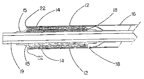
be covered (15) or uncovered (Fig. 9). At least a portion of the endoluminal
device is
pressed into a covered or uncovered endo-prosthesis mounting member to anchor
the
endoluminal device on the delivery catheter and prevent the endoluminal device
from
moving along the length of the catheter. Materials with a tacky surface are
useful with the
endo-prosthesis mounting member, particularly in combination with a lubricious
sheath
material. The endo-prosthesis mounting member eliminates the need for barrier,
or
retention, means placed at the proximal and distal end of the endoluminal
device. In
addition to added flexibility imparted to the deployment system without the
barrier means,
the profile of the sheath and endoluminal device combination is reduced
without the barrier
means. In yet another embodiment, the endo-prosthesis mounting member is in
the form of
an inflatable balloon (Fig -10, part 18a). Suitable materials for the endo-
prosthesis mounting
member include, but are not limited to, silicones, silicone foams,
polyurethane, polyurethane
foams, and polytetrafluoroethylene foams or combinations thereof. The endo-
prosthesis
mounting member is attached to the outer wall of the delivery catheter with
adhesives, heat,
or other suitable means.
A non-inflatable endo-prosthesis mounting member is preferably enclosed with a
covering (15) in the form of a polymeric material. The polymeric material is
preferably a
fluoropolymer-based material. Porous expanded polytetrafluoroethylene is the
preferred
fluoropolymer for enclosing the compressible material. Other suitable
polymeric materials
include, but are not limited to, silicone, polyurethane, polyester, and the
lilce.
E~z~les
Example I
This example describes the construction of a deployment system of the present
invention. Construction of the system began with the preparation of a distal
catheter shaft
for receiving an expandable stent. Once the distal catheter was prepared, the
expandable
stent was placed within a sheath - deployment line. The distal catheter
portion of this
combination was attached to a primary catheter shaft. The deployment line
portion was then
CA 02513322 2007-11-28
routed through the primary catheter to a control knob. The control knob was
part of a hub
located proximally on the primary catheter. The sheath portion of the sheath -
deployment
line was in the form of a single-walled tube.
A tubular material three inches long was obtained from Bumham Polymeric, Inc.,
Glens Falls, NY for use as the distal catheter shaft. The tube was made of a
potyether block
amide rnaterial; commonly known as PEBAX resin and reinforced with a
stainless steel
braid. The outer diameter (OD) was 1.01 mm and the inner diameter (ID) was
0.76mm. An
endo-prosthesis mounfing member in the form of a compressible material was
then placed
on the catheter.
To place the endo-prosthesis mounting member on the catheter, the catheter was
mounted on a mandret having an outer diameter of 0.74mm. A film of porous
expanded
polytetrafluoroethylene (ePTFE) was obtained according to the teachings in
U.S. Patent No.
5,814,405, issued to Branca. A discontinuous coating of fluorinated ethylene
propylene
(FEP) was applied to one side of the ePTFE material in accordance with U.S.
Patent No.
6,159,565, issued to Campbell et al. An edge of the ePTFE - FEP composite film
two
inches wide was attached with heat to the catheter shaft. After initial
attachment, the
film was wrapped around the catheter shaft forty-five (45) times under light
tension. With
every fifth wrap of the film, and on the final layer, the film is further
attached to itself with
heat supplied by a soldering iron.
This procedure provided a endo-prosthesis mounting member in the form of a
compressible material, or compliant "pillow," on the distal catheter shaft.
The expandable
stent was mounted over the endo=prosthesis mounting member. The endo-
prosthesis
mounting member provides a means of retaining an expandable stent on the
catheter shaft
during storage, delivery to an implantation site, and deployment of the
expandable stent at
the implantation site. Optionally, the endo-prosthesis mounting member may be
reinforced
with a thin coating of an elastomeric material such as silicone, urethane,
and/or a
fluoroelastomer.
An eight (8) cell, 6mm diameter, nitinol stent was obtained from Medinol Ltd.,
Tel-
Aviv, Israel. The stent was placed over the endo-prosthesis mounting member of
the
catheter in an expanded state. The combination was placed within a machine
having a
mechanical iris that compacts or compresses the stent portion of the assembly
onto the
endo-prosthesis mounting member. While retained in the mechanical iris
machine, the stent
was reduced in temperature from room temperature (c. 22 C) to approximately
five degrees
centigrade (5 C). At the reduced temperature, the iris machine was actuated to
compact, or
collapse, the stent onto the endo-prosthesis mounting member. While in the
refrigerated
11
CA 02513322 2007-11-28
and compressed configuration, the catheter, endo-prosthesis mounting member,
and stent
were placed within a sheath - deployment tine of the present invention.
The sheath - deployment line having a length equal to, or greater than, the
length of
the final deployment system was made as follows. A length of stainless steel
mandrel (c.
1 m) measuring 1.89mm in diameter was covered with a tubular extruded ePTFE
material
having an overall length of about 200cm. The tubular ePTFE material had an
outer diameter
of 1.41 mm, a wall thickness of 0.05mm, and an average longitudinal tensile
strength of
3.52kgf with an average circumferentiai strength of 0.169kgf. The tubular
ePTFE material
also had an average mass/iength of 0.0473g/ft with an average Matrix Tensile
Strength of
69,125 PSI. At one end (proximal end), the tubular ePTFE material was bunched
together
on the mandrel, while the opposite end (distal end) of the ePTFE material
remained smooth
on the mandrel.
The first few centimeters of the tubular ePTFE material was sacrificed and the
next
5cm of the distal end (smoothed end) of the extruded ePTFE material was then
reinforced
with a composite fluoropolymer material as follows. The ePTFE-covered mandrel
was
attached to retaining chucks on a film-wrapping machine. Afirst reference line
located
approximately 5cm from the end of the smooth ppraon of the extruded ePTFE
material was
circurnferentially drawn around the material with a permanent marker (SHARPIE
). A 5cm
wide composite membrane made of expanded polytetrafluoroethylene (ePTFE) and
fluorinated ethylene propylene (FEP) was applied proximal from the first
reference line on
the extruded ePTFE material so the FEP portion of the composite membrane was
against
the extruded ePTFE material. The composite membrane was wrapped around the
ePTFE
covered mandrel two times so that the primary strength of the extruded ePTFE
material was
oriented perpendicular to the longitudinal axis of the mandrel. The composite
membrane
was initially tacked in place on the extruded ePTFE material with heat applied
from a
soldering iron. The composite ePTFE/FEP material had a density of about
2.14g/cm3, a
thickness of 0.005mm, and tensile strengths of about 340 KPa (about 49,000
psi) in a first
direction and of about 120 KPa,(about 17,000 psi) in a second direction
(perpendicular to the
first direction). The tensile measurements were performed on an Instron
Tensile Machine
(Instron Corporation, Canton, MA) at 200mm/min. load rate with 2.5cm (one
inch) jaw
spacing.
Material of the sheath - deployment line construction adjacent to the
reinforced
portion was smoothed out along the mandrel and a second reference line was
drawn around
the material 5cm from the first reference line.
A second portion of the sheath - deployment line construction was reinforced
as
follows. A second reference tine was drawn around the extruded ePTFE material
5cm from
the proximal end of the first reinforced portion. Using the second reference
line to align a
12
CA 02513322 2005-07-14
WO 2004/066809 PCT/US2004/001046
2cm wide strip of the above-mentioned ePTFE/FEP composite membrane, the
composite
membrane was wrapped once around the remaining portion of the extruded ePTFE
material
to form a second reinforced portion of the sheath - deployment line of the
present invention.
The second reinforced portion was about 2cm in length. The composite
reinforcing
membrane material was attached to the extruded ePTFE material as described
above, with
the exception that the major strength component of the material was parallel
to the axis of
the mandrel.
Any air trapped in the construction was removed by applying a sacrificial
layer of
ePTFE tightly around the construction. A one inch (2.54cm) wide film of ePTFE
was
helically overwrapped around the reinforced portion of the construction. Two
layers of the
ePTFE film were applied in one direction and two layers were applied in the
opposite
direction. The construction with sacrificial layers were then placed in an
oven heated to
320 C for eight minutes. Upon removal from the heated oven, the combination
was allowed
to cool to room temperature. The sacrificial ePTFE material was then removed.
The construction was then removed from the mandrel and another mandrel (1.83mm
diameter X 30.5cm long) inserted into the reinforced end of the construction.
With the
mandrel supporting the reinforced end, a 5mm long slit was made proximal to
the reinforced
portion of the sheath - deployment line construction. A second mandrel
was.placed inside
the construction up to the 5mm slit where it exited the construction. The
proximal portion of
the sheath - deployment line construction was converted into a filament by
placing the
proximal end into the chucks of the film wrapper chucks and rotating the film
wrapper
approximately 2,800 times while the mandrel with the reinforced construction
was
immobilized. After the construction was spun into a filament, the filament was
strengthened
by briefly applying heat to the filament with a soldering iron set at 450 C.
The strengthened
filament was smoothed and rendered more uniform in diameter by passing the
filament over
a 1.8cm diameter X 3.8cm long dowel heated to approximately 320 C. The
filament was
passed over the heated dowel at a 45 angle under slight tension. This process
was
repeated trio more times over the entire length of the filament.
The filament portion of the sheath - deployment line of the present invention
veas
routed through a lumen of a primary catheter and connected to a control knob.
The control
knob was part of a hub located at the proximal end of the primary catheter.
When the
deployment line portion of the sheath - deployment line was pulled, the sheath
portion was
retracted from around the stent.
Example 2
13
CA 02513322 2005-07-14
WO 2004/066809 PCT/US2004/001046
This example describes the construction of a deployment system of the present
invention. Construction of the system begins with the preparation of a distal
catheter shaft
for receiving an expandable stent. Once the distal catheter was prepared, the
expandable
stent was placed within a sheath - deployment line. The distal catheter
portion of this
combination was attached to a primary catheter shaft. The deployment line
portion was then
routed through the primary catheter to a control knob. The control knob was
part of a hub
located proximally on the primary catheter. The sheath portion of the sheath -
deployment
line was in the form of a double-walled tube.
A tubular material three inches long was obtained from Burnham Polymeric,
Inc.,
Glens Falls, NY for use as the distal catheter shaft. The tube was made of a
polyether block
amide material, commonly known as PEBAX resin and reinforced with a stainless
steel
braid. The outer diameter (OD) was 1.01 mm and the inner diameter (ID) was
0.76 mm. A
endo-prosthesis mounting member in the form of a compressible material was
then placed
on the catheter. To place the endo-prosthesis mounting member on the catheter,
the
catheter was mounted on a mandrel having an outer diameter of 0.74 mm. A film
of porous
expanded polytetrafluoroethylene (ePTFE) was obtained according to the
teachings in U.S.
Patent No. 5,814,405, issued to Branca, which is incorporated herein by
reference. A
discontinuous coating of fluorinated ethylene-propylene (FEP) was applied to
one side of-the
ePTFE material in accordance with U.S. Patent No. 6,159,565, issued to
Campbell et al.,
which is incorporated herein by reference. An edge of the ePTFE - FEP
composite film two
inches wide was attached with heat to the catheter shaft. After initial
attachment, the film
was wrapped around the catheter shaft forty-five (45) times under light
tension. With every
fifth wrap of the film, and on the final layer, the film is further attached
to itself with heat. This
procedure provides a endo-prosthesis mounting member on the distal catheter
shaft. The
expandable stent is mounted over the endo-prosthesis mounting member. The endo-
prosthesis mounting member provides a means of retaining an expandable stent
on the
catheter shaft during storage, delivery to an implantation site, and
deployment of the
expandable stent at the implantation site. Optionally, the endo-prosthesis
mounting member
may be reinforced with a thin coating of an elastomeric material such as
silicone, urethane,
and/or a fluoroelastomer.
An eight (8) cell, 6mm diameter, nitinol stent was obtained from iviedinol
Ltd., Tal-
Aviv, Israel. The stent was placed over the endo-prosthesis mounting member of
the
catheter in an expanded state. The combination was placed within a machine
having a
mechanical iris that compacts or compresses the stent portion of the assembly
onto the
endo-prosthesis mounting member. While retained in the mechanical iris
machine, the stent
was reduced in temperature from room temperature to approximately five degrees
centigrade (5 C). At the reduced temperature, the iris machine was actuated to
compact, or
14
CA 02513322 2007-11-28
collapse, the stent onto the endo-prosthesis mounfiing member. While in the
refrigerated,
compressed configuration, the catheter, endo-prosthesis mounting member, and
sterit were
placed within a sheath - deployment line of the present invention.
The sheath - deployment line having a length equal to, or greater than, the
length of
the final deployment system was made as follows. A stainless steel mandrel
measuring 1.73
mm in diameter was covered with a sacrificial layer of ePTFE. The sacrificial
ePTFE
material aids in removal of the sheath - deployment line from the mandrel. Two
wraps of a
thin, polytetrafluoroethylene (PTFE) membrane were applied to the mandrel. The
ePTFE
membrane was applied so the primary strength of the film was oriented parallel
with the
longitudinal axis of the mandrel. The film was initially tacked in place with
heat applied with
a soldering iron. The membrane thickness measured about 0.0002" (0.005 mm) and
had
tensile strengths of about 49,000 psi (about 340 KPa) in a first direction and
of about 17,000
psi (about.120 fCPa) in a second direction (perpendicular to the first
direction). The tensile
measurements were performed at 200mm/min. load rate with a 1" (2.5 cm) jaw
spacing. The
membrane had a density of about 2.14g1cm3. The membrane was further modified
by the
application of an FEP coating on one side in accordance with U.S. Patent No.
6,159,565,
issued to Campbell et al., which is incorporated herein by reference. Next,
two wraps of
another ePTFE film made according to the teachings of Bacino in U.S. Patent
No. 5,476,589
and further modified with a discontinuous layer of an FEP material applied to
one side of the
ePTFE film were applied to one end of the construction (approx. 1" wide). U.S.
Patent No.
5,476,589. These two wraps had the primary strength
direction of the film oriented perpendicular to the mandrel's longitudinal
axis. These layers
of film provide additional "hoop" or "radial" strength to the sheath -
deployment line
construct. The mandrel and sheath - deployment line construct were placed in
an air
convection oven obtained from The Grieve Corporation, Round Lake, IL, and
subjected to a
thermal treatment of 320 C for 12 minutes. After air cooling, the ePTFE/FEP
tube construct
was removed from the mandrel and the sacrificial ePTFE layer removed. In this
example, a
length of sheath - deployment line extending beyond the end of the stent was
provided. The
additional length of sheath - deployment tine was folded back over sheath
portion enclosing
the stent to form a double-walled construct. The double-walled sheath -
deployment line
had an inner wall and an outer wall. The inner wall was against the stent and
the outer wall
included the integral deployment line portion of the construct. The construct
was then
attached to a primary catheter shaft using heat and standard materials.
The deployment line portion of the sheath - depioyment line was made by
splitting
the sheath - deployment line along its length from a proximal end up to, but
not including,
the sheath portion enclosing the stent. The material thus obtained was
gathered into a
filament by rolling the material. Heat was applied to the material to set the
material in the
CA 02513322 2005-07-14
WO 2004/066809 PCT/US2004/001046
filamentous form. The deployment line filament was routed through a lumen in
the primary
catheter and connected to a control knob. The control knob was part of a hub
located at the
proximal end of the primary catheter. When the deployment line portion of the
sheath -
deployment line was pulled, the sheath portion was retracted from around the
stent.
Example 3
This example describes the incorporation of a means for initiating or
maintaining
conversion of the sheath portion of the sheath - deployment line to deployment
line by
introducing perforations and intentional stress risers into the sheath.
The sheath - deployment line from Example 2 is modified as follows. Prior to
rolling
the sheath portion into a double-walled construct and loading the stent
therein, the sheath is
perforated and/or supplied with "stress risers" that facilitate in separation
of the tubular
sheath upon retraction of the deployment line portion. An appropriate laser
for making the
perforations or stress risers is a 20 watt C 2laser obtained from Universal
Laser Systems,
Scottsdale, AZ. To form the perforations in the sheath portion, the sheath is
placed on a
sandblasted stainless steel mandrel and exposed to the laser to cut a series
of holes in a
- part of the tube that will subsequently serve as the outer wall of the
double-walled construct.
The geometry of the holes can be varied depending on the application. The
perforated
sheath portion is used on a deployment line system of the present invention as
described in
Example 2. In this example, tension applied to the deployment line portion at
the hub end of
the catheter results in retraction of the sheath from around the stent and
also results in
parting the sheath at the perforations. As the sheath portion is separated,
the sheath
material becomes convertible to deployment line.
Example 4
This eaeample describes the incorporation of a means for initiating or
maintaining
conversion of ths sheath portion of the sheath - deployment line to deployment
line by the
use of an appropriate splitting means.
The primary catheter from Example 2 is modified as follows. The primary
portion of
the catheter is provided with a notch in the wall in 180 degrees opposition
and slightly distal
to the entry point of the deployment line portion into the catheter lumen. The
notch is further
modified to provide a small cutting edge in the notch. In one embodiment, the
cutting edge
is simply attached to the notch with heat, adhesives, and the like. In another
embodiment,
the cutting edge is formed by exposing a portion of a metallic braid used to
reinforce the
catheter shaft and forming the braid into a cutting edge. In this example,
tension applied to
16
CA 02513322 2005-07-14
WO 2004/066809 PCT/US2004/001046
the deployment line portion at the hub end of the catheter results in
retraction of the sheath
from around the stent and also results in parting the sheath at the
perforations. As the
sheath portion is separated, the sheath material becomes convertible to
deployment line.
Example 5
This example describes the construction of a deployment system of the present
invention for use in the delivery and deployment of both self-expanding as
well as balloon
expandable devices. The deployment system of this example utilizes an endo-
prosthesis
mounting member in the form of an inflatable balloon.
A sheath - deployment line having a length equal to, or greater than, the
length of
the final deployment system is made as follows. A stainless steel mandrel
measuring 1.73
mm in diameter is covered with a sacrificial tube of ePTFE. The sacrificial
ePTFE material
aids in removal of the sheath - deployment line from the mandrel. Two wraps of
a thin,
polytetrafluoroethylene (PTFE) membrane is applied to the mandrel. The ePTFE
membrane
is applied so the primary strength of the film is oriented parallel with the
longitudinal axis of
the mandrel. The film is initially tacked in place with heat applied with a
soldering iron. The
membrane thickness measured about 0.0002" (0.005 mm) and had tensile strengths
of
about 49,000 psi (about 340 KPa) in a first direction and about 17,000 psi
(about 120 KPa) in
a second direction (perpendicular to the first direction). The tensile
measurements are
performed at 200mm/min. load rate with a 1 inch (2.5 cm) jaw spacing. The
membrane has
a density of about 2.14g/cm3 . The membrane is further modified by the
application of a
fluorinated ethylene propylene (FEP) coating on one side in accordance with
U.S. Patent No.
6,159,565, issued to Campbell et al. and incorporated herein by reference.
Next, two wraps
of another ePTFE film made according to the teachings of Bacino in U.S. Patent
No.
5,476,589, which is incorporated herein by reference, and further modified
with a
discontinuous layer of an FEP material applied to one side of the ePTFE film
are applied to
one end of the construction (approx. 1" wide). These txvo wraps have the
primary strength
direction of the film oriented perpendicular to the mandrel's longitudinal
axis. These layers
of film provide additional "hoop" or "radiaP" strength to the sheath -
deployment line
construct. The mandrel and sheath - deployment line construct are placed in an
air
convection oven obtained from The Grieve Corporation, Round Lake, IL, and
subjected to a
thermal treatment of 320 C for 12 minutes. After air cooling, the ePTFE/FEP
tube construct
is removed from the mandrel and the sacrificial ePTFE layer removed. Placement
of this
construct over an expandable stent and formation of a deployment line portion
therefrom is
described below.
17
CA 02513322 2007-11-28
As seen in Figure 10, a bafloon expandable NIRfleXTu stent (14), available
from
Medinol Ltd ,Tel-Aviv, Israel, is placed over and compacted around a deflated
and coilapsed
angioplasty balloon mounted on a delivery catheter shaft (19). The angioplasty
balloon is
made in accordance with U.S. 5,752,934 to Campbell et a!. available
from W. L. Gore & Associates, Inc., Flagstaff, AZ under the
tradename APTERAO angioplasty balloon. The APTERA angioplasty balloon serves
as
an endo-prosthesis mounting member (18a) for receiving and retaining the
compacted stent
(14).
While the stent is confined in a compacted configuration, a length of sheath -
deployment line (12) is placed over the compacted stent and extended beyond
the end of
the stent. The additional length of sheath - deployment line is folded back
over sheath
pordon enclosing the stent to form a double-walled constrtiction. The double-
walled sheath
- deployment line has an inner wall and an outer wall. The inner wall is
against the stent
and the outer wall includes the integral deployment line portion of the
construct.
The deployment line portion of the sheath - deployment line is made by
splitting the
sheath - deployment line along its length from the proi(imal end toward the
distal end for a
distance. The slit can range in length from about one centimeter to
substantially the entire
length of the sheath - deployment line construction up to, but not including,
the sheath
portion enclosing the stent. It is preferred to form the deployment line
portion near the
proximal end of the delivery catheter. The materiaf thus obtained is gathered
into a fiiament
by rolling the material. Heat is applied to the material to set the material
in the filamentous
form. The sheath - deployment line is routed through a dedicated lumen in the
delivery
catheter and e)(ts at a hub where the deployment line portion is attached to a
control knob.
The control knob is part of a hub located at the proximal end of the primary
catheter. When
tension is applied to the deployment line portion of the sheath - deployment
line, the sheath
por6on retracts from around the stent. Removal of the sheath portion from the
underlying
stent frees the stent to expand: The N1RfIex7m stent of this example is
expanded by inflating
the APTERA angioplasty balloon. Once the stent is expanded, the balloon is
deflated and
the delivery catheter along with the sheath - deployment line construction
removed from the
implant recipient. When self-expanding stents are used in the present
invention, the balloon
is useful as an endo-prosthesis mounting member.
18