Note : Les descriptions sont présentées dans la langue officielle dans laquelle elles ont été soumises.
CA 02514993 2005-08-02
WO 2004/072770 PCT/US2004/001576
METHOD AND APPARATUS FOR TESTING
NETWORK DATA SIGNALS IN A WAVELENGTH
DIVISION MULTIPLEXED OPTICAL NETWORK
TECHNICAL FIELD
The present invention relates to the transmission of information over fiber
optics, and
more particularly to determining network and data integrity for wavelength
multiplexed
optical networks.
BACKGROUND ART
Optical Wavelength Division Multiplexing ("WDM") has become a standard
l0 technology for fiber optic communication systems for the transmission of
voice, data, the
Internet, etc. WDM systems employ signals consisting of a number of different,
unique
wavelengths or channels, to transmit information. Each wavelength channel is
modulated by
a data signal, typically in the form of a stream of bits, which encode the
voice or Internet
traffic. As a result, a significant number of data signals may be transmitted
simultaneously
over a single optical fiber using WDM technology.
Despite the substantially higher fiber bandwidth utilization provided by WDM
technology, multiplexing and demultiplexing create a number of serious
problems that must
be overcome, such as cross-talk, equalization, chromatic dispersion, network
management,
and routing of the information signals, for such systems to be commercially
viable. Testing
and troubleshooting problems are also greatly complicated by the additional
components and
complexity of a WDM network. Without additional testing tools, network
maintenance is
very difficult, resulting in significant time and effort expended to install
and maintain a
WDM network.
Multiplexing involves the process of combining multiple signals (each signal
on its
own wavelength) into a single multiple wavelength WDM signal. De-multiplexing
is the
opposite process in which each single wavelength is extracted and decomposed
from the
multiple wavelength signal. Each signal is thus reconstructed to match the
original
information signal before multiplexing.
CA 02514993 2005-08-02
WO 2004/072770 PCT/US2004/001576
Each wavelength channel has the capability to carry several gigabits of binary
data per
second. This is also referred to as the modulation rate. As the modulation
rate is increased,
more data can be carried, since each bit transmitted causes the carrier signal
to be modulated.
The modulation rate is currently defined by industry standards, SONET
("Synchronous
Optical NETwork") developed by the American National Standards Institute
("ANSI") in the
United States and used in North America, and SDH ("Synchronous Digital
Hierarchy")
developed by the International Telecommunication Union ("TTU") and used
throughout most
of the rest of the world.
Currently, nearly all information transmitted over fiber, whether voice, data,
Tnternet,
or e-mail, is done using the SONET/SDH standard. However, other standards for
transmission of high data rates are emerging, such as Gigabit Ethernet and 10
Gigabit
Ethernet. The present invention applies to the transmission of SONET/SDH,
Ethernet, or
other standards or proprietary protocols that may emerge in the future.
Understandably, as with many standards, use of the SONET/SDH standard has
become not only typical but effectively required, because both the network
transmitter and
the network receiver must operate under identical standards so that the
receiver can decipher
the information sent by the transmitter. By using equipment that conforms to
the standards,
carriers (companies that build and operate networks) may then mix equipment
from different
vendors for their networks.
One reason SONET has become so successful is that it was designed so that the
integrity of the data stream can be verified, even when live traffic is being
transmitted. There
are a number of established test equipment vendors building test-sets for
analyzing SONET
and SDH. Precise measurements of the error performance of the bit stream can
be made. ,
Equivalent test equipment can be expected in the future for Ethernet and other
standards that
may emerge, since test and verification is required to operate a successful
network.
Current technology allows for a modulation rate of between 51 Megabits per
second
("Mbps") and 10 Gigabits per second ("Gbps"). An increase in the modulation
rate results in
a spectrally wider channel signal. Consequently, the wider signal and narrower
spacing
between channels mean that the signals are closer together, and thus harder to
separate. As a
3o result, data loss and distortion, such as crosstalk from adjacent signals,
may occur.
As greater and greater amounts of data needed to be transmitted, further
technological
improvements led to the deployment of an improved, higher capacity protocol
called dense
2
CA 02514993 2005-08-02
WO 2004/072770 PCT/US2004/001576
wavelength division multiplexing ("DWDM"), which allows even more data streams
(channels) to be transmitted over a single strand of fiber.
For data quality and system performance analysis, there are a number of very
well
established test equipment vendors who manufacture test-sets and testing
mechanisms for
analyzing SONET/SDH networks, as previously indicated. There axe also
established
methods to look at the WDM signal, particularly on a physical layer level. For
example, by
looking at the WDM spectrum, various anomalies can be determined, such as
cross-talk,
correct channel wavelength and power levels, channel power equalization, and
background
noise levels.
to Unfortunately, there is no effective way to combine the WDM and the SONET
analytical techniques. Further, in the typical situation where there is a
particular
SONET/SDH (or other) signal of interest in a WDM on a fiber, it is difficult
to extract and
analyze that individual SONET/SDH (or other) signal.
The difficulty in using contemporary SONET/SDH testing equipment to monitor
just
one single WDM wavelength resides in the SONET/SDH receivers, which are
designed to
receive a single SONET/SDH data stream. The receivers therefore cannot be used
directly to
analyze WDM transmissions. If a WDM signal is directly inputted into a
SONET/SDH
analyzer, the test set will be unable to extract all the different individual
data signals. The
output will be meaningless and the test useless. It is not possible to extract
each individual
wavelength so that each can be analyzed individually.
Each single wavelength or carrier channel may carry upwards of 10 gigabits of
data
per second, each made up of thousands of tributary channels, called T1 lines.
Carriers and
equipment vendors find it necessary to be able to analyze each T1 and to
verify each for
quality. The scale of the challenge is daunting: to monitor all these
information channels
within the single SONETISDH carrier channel wavelength, and then to multiply
that by up to
81 or more different wavelengths that are possible in a WDM network.
The monitoring and testing generally falls into two analysis categories. One
category
is analyzing for defects on networks carrying live traffic, ,also referred to
as "in service"
testing. If a problem occurs, a network element will signal an alarm, which is
transmitted
inside the data overhead so that the remainder of the network (and the network
operators) can
identify the problem and react to it. It is also possible to detect
transmission errors since
parity checking is usually specified in the standards. By looking at the
overhead for alarms
and defects, the health and the quality of the circuit can be determined.
3
CA 02514993 2005-08-02
WO 2004/072770 PCT/US2004/001576
The other analysis category is bit error rate ("BER") testing. This is "out-of
service"
monitoring that is performed on a line when it is out of service. In that
state, there is nothing
on the line except what the monitoring tester puts on it. Typically, a pseudo-
random test
pattern, such as 223-I, is utilized to send a number of bits in pseudo-random
sequence from
one end of the line to the other. It is then possible to identify if any of
those bits is received
in error at the other end. Note that this out-of-service bit error rate
testing needs to be done
for every one of those hundreds or thousands of information channels across
the plurality of
carrier channel wavelengths.
A long felt need therefore remains for a method and apparatus for testing
SONET/SDH signals on~a WDM network, in which established in-service and out-of-
service
SONET/SDH testing protocols and capabilities can be advantageously employed in
an
accurate, rapid, effective, timely, and cost effective manner. A need also
remains for a
testing capability that is automatic and can therefore execute when and as
needed, regardless
of operator availability, and is not subject to possible operator error. The
same need will
exist for the testing of emerging standards that will be carried in WDM
channels.
Solutions to problems of this sort have been long sought, but have long eluded
those
skilled in the art.
DISCLOSURE OF THE INVENTION
The present invention provides a method and apparatus for testing network data
2o signals in an optical wavelength division multiplexing network.
An optical wavelength division multiplexing function and a network analysis
function
are provided. The optical wavelength division multiplexing function is
utilized to produce a
single wavelength carrier signal. The single wavelength carrier signal is
passed to the
network analysis function. The network analysis function is used to perform at
least network
signal level analysis on the single wavelength carrier signal. The optical
wavelength division
multiplexing function is then incremented through a plurality of the single
wavelength carrier
signals, providing faster and more accurate testing of network data signals in
optical
wavelength division multiplexing networks.
Certain embodiments of the invention have other advantages in addition to or
in place
of those mentioned above. The advantages will become apparent to those skilled
in the art
from a reading of the following detailed description when taken with reference
to the
accompanying drawings.
4
CA 02514993 2005-08-02
WO 2004/072770 PCT/US2004/001576
BRIEF DESCRIPTION OF THE DRAWINGS
FIG. 1 is a schematic view of a system for testing network data signals in an
optical
wavelength division multiplexing network;
FIG. 2 is a schematic view of a system configuration for channel physical
layer
analysis and channel discovery for an optical wavelength division multiplexing
network;
FIG. 3 is a schematic view of a system configuration for in-service monitoring
of an
optical wavelength division multiplexing network;
FIG. 4 is a schematic view of a system configuration for out-of service
testing with a
single wavelength protocol on an optical wavelength division multiplexing
network;
FIG. 5 is a schematic view of the system configuration of FIG. 4 adapted for
out-of-
service bit error rate testing in the presence of multiple wavelength signals
on an optical
wavelength division multiplexing network; and
FIG. 6 is a flow chart of a method for testing network data signals in an
optical
wavelength division multiplexing network.
BEST MODE FOR CARRYING OUT THE INVENTION
Referring now to FIG. l, therein is shown, in schematic form, a system 100 for
testing
Synchronous Optical NETwork ("SONET") or Synchronous Digital Hierarchy ("SDH")
or
other data carrying network signals in an optical wavelength division
multiplexing network.
Current Wavelength Division Multiplexing ("WDM") technology typically allows
for up to
81 information signals, each carried on a different wavelength, to travel on a
single-mode
optical fiber using a single WDM signal. Increases in the number of channels
have been
accomplished by shrinking the spectral separation between the channels and by
adding new
channels. The industry has referred to systems with narrow spacing as Dense
Wavelength
Division Multiplexing or DWDM. The current standards for DWDM signals include
50 GHz
(about 0.4 nm) and 100 GHz (about 0.8 nm) between optical channels. The
optical
networking media includes reports of systems with spacing down to 10 GHz,
making possible
networks with 1000 or more wavelength channels within the useful spectrum for
transmission
across optical fibers, and through optical amplifiers.
The International Telecommunication Union ("ITU") has defined the wavelengths
and
wavelength spacing in the 6.692 standard. In the TTU wavelength table
A.1/G.692 below,
5
CA 02514993 2005-08-02
WO 2004/072770 PCT/US2004/001576
nominal central frequencies are based on a 50 GHz minimum channel spacing
anchored to a
193.10 THz reference.
Table A.1/G.692 -Nominal central frequencies
Nominal central frequenciesNominal central frequenciesNominal central
(THz) for spacings (THz) for spacings of wavelengths (nm)
of 50 GHz 100 GHz
and above
196.10 196.10 1528.77
196.05 - 1529.16
196.00 196.00 1529.55
195.95 - 1529.94
195.90 195.90 1530.33
195.85 - 1530.72
195.80 195.80 1531.12
195.75 - 1531.51
195.70 195.70 1531.90
195.65 - 1532.29
195.60 195.60 1532.68
195.55 - 1533.07
195.50 195.50 1533.47
195.45 - 1533.86
195.40 195.40 1534.25
195.35 - 1534.64
195.30 195.30 1535.04
195.25 - 1535.43
195.20 195.20 1535.82
195.15 - 1536.22
195.10 195.10 1536.61
195.05 - 1537.00
195.00 195.00 -1537.40
194.95 - 1537.79
194.90 194.90 1538.19
194.85 - 1538.58
194.80 194.80 1538.98
194.75 - 1539.37
194.70 194.70 1539.77
194.65 - 1540.16
194.60 194.60 1540.56
194.55 - 1540.95
194.50 194.50 1541.35
194.45 - 1541.75
194.40 194.40 1542.14
194.35 - 1542.54
194.30 194.30 1542.94
194.25 - 1543.33
194.20 194.20 1543.73
194.15 - 1544.13
194.10 194.10 1544.53
194:05 - 1544.92
194.00 194.00 1545.32
193.95 - 1545.72
193.90 193.90 1546.12
193.85 - 1546.52
193.80 193.80 1546.92
6
CA 02514993 2005-08-02
WO 2004/072770 PCT/US2004/001576
Nominal central frequenciesNominal central frequenciesNominal central
(THz) for spacings (THz) for spacings of wavelengths (nm)
of 50 GHz 100 GHz
and above
193.75 - 1547.32
193.70 193.70 1547.72
193.65 - 1548.11
193.60 193.60 1548.51
193.55 - 1548.91
193.50 193.50 1549.32
193.45 - 1549.72
193.40 193.40 1550.12
193.35 - 1550.52
193.30 193.30 1550.92
193.25 - 1551.32
193.20 193.20 1551.72
193.15 - 1552.12
193.10 193.10 1552.52
193.05 - 1552.93
193.00 193.00 1553.33
192.95 - 1553.73
192.90 192.90 1554.13
192.85 - 1554.54
192.80 192.80 1554.94
192.75 - 1555.34
192.70 192.70 1555.75
192.65 - 1556.15
192.60 192.60 1556.55
192.55 - 1556.96
192.50 192.50 1557.36
192.45 - 1557.77
192.40 192.40 1558.17
192.35 - 1558.58
192.30 192.30 1558.98
192.25 - 1559.39
192.20 192.20 1559.79
192.15 - 1560.20
192.10 192.10 1560.61
NOTE - The endpoints
of this table are
illustrative only.
Future evolutions
of multichannel
systems are
anticipated to include
frequencies beyond
those limits.
The system 100, suitable for use on a DWDM network, includes a DWDM module
102 and a network analysis module 104 that provide, respectively, an optical
wavelength
division multiplexing function and a network analysis function for the system
100. Both the
DWDM module 102 and the network analysis module 104 are under the control of
suitable
control circuitry, such as a computer or central processing unit ("CPU") 106.
The DWDM module 102 includes a wavelength drop section 108 and a tunable laser
source 110. The wavelength drop section 108 and the tunable laser source 110
in the DWDM
module 102 may be selectably utilized as needed for testing optical signals,
as further
described below.
7
CA 02514993 2005-08-02
WO 2004/072770 PCT/US2004/001576
Optical signals enter the system 100 through an input 112 that conducts the
optical
signals to the wavelength drop section 108 of the DWDM module 102. The optical
signals
are then conducted from the wavelength drop section 108 through a first
internal optical
coupling 114 to the network analysis module 104. From there, the optical
signals are
conducted by a second internal optical coupling 116 to the tunable laser
source 110 in the
DWDM module 102, and from there to an output 118 for the system 100.
The system 100 is configured so that the wavelength drop section 108, the
tunable
laser source 110, and/or the network analysis module 104 may be selectively
bypassed as
appropriate for the various tests and analyses to be performed, as. further
described herein.
A suitable DWDM module is commercially available from Sunrise Telecom (San
Jose, CA), and suitable network analysis modules may be obtained from Agilent
Technologies (Palo Alto, CA) and Sunrise Telecom (San Jose, CA).
lZeferring now to FIG. 2, therein is shown schematically a system
configuration for
DWDM channel physical layer analysis and channel discovery for a DWDM network
200.
i5 For clarity of illustration in this and subsequent Figures, only those
portions of the system
100 actively utilized in the configuration being described will be included in
the particular
drawing Figure. All such configurations are easily enabled under the control
of the CPU 106.
As shown in FIG. 2, it is possible to determine initially which channels or
wavelengths are available on the DWDM network 200. As is well understood in
the art, the
2o DWDM network 200 will have a DWDM signal 202 carried over a single fiber
optic cable.
That single fiber optical cable will typically be carrying multiple signal
wavelengths or
channels, all of which are connected by that single fiber to the input 112 for
analysis by the
DWDM module 102.
The CPU 106 then controls the DWDM module 102 to scan the DWDM signal 202 to
25 see which channels or wavelengths are occupied with information signals.
(Alternatively, an
operator manually inputs the number and the wavelength of each occupied
channel.) This
data can then be utilized to determine which channels to monitor or test; that
is, the occupied
wavelengths become the grid across which the test and monitoring take place.
The DWDM module 102 thus performs a preliminary physical measurement and
3o analysis, identifying the DWDM channels automatically. This step provides
for
automatically identifying and confirming the occupied channels, thereby
optionally
eliminating the need to manually determine and verify the occupied wavelengths
before
proceeding with monitoring, analyzing, and/or testing.
8
CA 02514993 2005-08-02
WO 2004/072770 PCT/US2004/001576
Referring now to FIG. 3, therein is shown schematically a system configuration
for in-
service monitoring of a DWDM network. The DWDM signal 202, provided from the
DWDM network 200, is provided to the wavelength drop section 108 of the DWDM
module
102. The wavelength drop section 108 is a conventional tunable optical filter
that isolates or
"drops" a single, specified wavelength, carried on the first internal optical
coupling 114, and
being output from the wavelength drop section 108 under the control and
specification of the
CPU 106. The single wavelength is then provided to the network analysis module
104 to
monitor the SONET, SDH, or other signals, such as for in-service alarm and
defect data.
The network analysis module 104 is itself largely wavelength agnostic, which
is both
advantageous and disadvantageous. The advantage is that the network analysis
module 104
is able to accept and analyze each wavelength without having to be
specifically tuned thereto,
but the disadvantage is that it can analyze only a single wavelength at a
time, thus requiring
the wavelength drop section 108. The network analysis module 104 then scans
the signal and
all tributary channels on the single wavelength, providing mapping, status,
alarm, and defect
information.
Once the testing for the specified wavelength has been completed and the
desired
length of time for monitoring has expired, the CPU 106 instructs the DWDM
module 102 to
change the wavelength drop section 108 to the next occupied wavelength in the
list or grid of
wavelengths across which the scanning analysis has been specified.
The CPU 106 then commands the network analysis module 104 to begin the testing
anew. Once that test is completed, the CPU 106 repeats the cycle again until
the entire
specified spectrum of the DWDM signal 202 has automatically been scanned and
analyzed,
without requiring any user or operator intervention or management.
Contrasted with in-service monitoring, out-of service testing provides greater
opportunities for analyzing the condition of the network. With in-service
monitoring, the
network analysis is relatively passive since live data is being carried on the
network. There is
thus little opportunity to test the network actively. In contrast, when the
network is out-of-
service, it can be intelligently perturbed and tested with suitable test
signals.
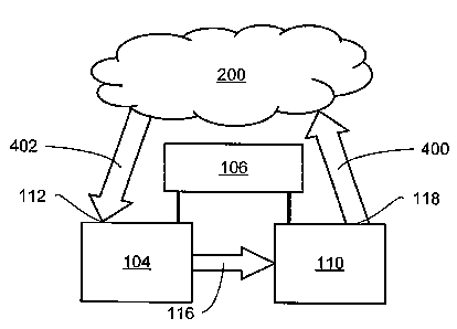
Referring now to FIG. 4, therein is shown schematically a system configuration
for
out-of service testing with a single wavelength protocol on a DWDM network. In
this
configuration, the CPU 106 instructs the network analysis module 104 to send
an information
signal that contains a test pattern, such as 223-1, in its payload, to the
tunable laser source 110
in the DWDM module 102. The test pattern signal from the network analysis
module 104 is
9
CA 02514993 2005-08-02
WO 2004/072770 PCT/US2004/001576
a single wavelength signal (typically at 1310 or 1550 nm), and is not suitable
for direct
transmission into a carrier channel wavelength of a DWDM network.
Since it is desired to test each of the available channel wavelengths in the
DWDM
network 200, the CPU 106 then instructs the tunable laser source 110 to
convert the
wavelength into one of the specified test wavelengths on the DWDM spectrum.
The test
wavelength signal is then coupled from the output 118 of the system 100 into
the DWDM
network 200 through an uplink fiber 400.
t~fter passing through the DWDM network 200, the test signal is returned
through a
downlink fiber 402 to the input 112 of the system 100 and returned to the
network analysis
l0 module 104.
Since the network analysis module's receiver can receive a wide band of
frequencies,
typically it will not be necessary to change the wavelength again before going
back to the
network analysis module 104 for analysis. With this loop in place, the network
analysis
module 104 can now perform a bit error rate ("BER") test and monitor the
particular
specified wavelength for data errors.
The test at the specified wavelength or channel continues for the desired time
interval
(which might be seconds or days in duration). During this test cycle, the
network analysis
module 104 will typically test each tributary channel within the single
wavelength. Then, the
CPU 106 instructs the tunable laser source 110 to change to the next specified
test
wavelength, and instructs the network analysis module 104 to begin the test
anew. The CPU
106 then repeats the cycle until all the specified wavelengths in the DWDM
network 200
have been automatically scanned and tested.
The system configuration shown in FIG. 4 assumes that there is no other
traffic on the
DWDM network 200. However, when the DWDM network 200 is not entirely out-of,,
service, there may be some other traffic on the system line. In that case, the
test environment
will not contain just the one wavelength that was originally injected into the
DWDM network
200 by the tunable laser source 110. Instead, other wavelengths (possibly
carrying live data
streams) will also be present.
Referring now to FIG. 5, therein is shown schematically a system configuration
3o similar to that illustrated in FIG. 4, but adapted for out-of service bit
error rate testing in the
presence of multiple wavelength signals on the output from the DWDM network
200. In this
case, the wavelength drop section 108 of the DWDM module 102 is actively used,
between
the downlink fiber 402 and the network analysis module 104.
CA 02514993 2005-08-02
WO 2004/072770 PCT/US2004/001576
More specifically, the multiple wavelengths on the downlink fiber 402 enter
the
system 100 through the input 112 and are processed in the wavelength drop
section 108 to
send only the single wavelength of interest to the network analysis module 104
through the
first internal optical coupling 114. This will typically be the same
wavelength frequency that
previously had been injected into the uplink fiber 400 by the tunable laser
source 110, but
may be a different wavelength. (For example, the DWDM network 200 may
transpose an
information signal onto a different wavelength, and the wavelength drop
section 108 will then
be configured so that the system verifies that the transposition was performed
properly.)
Upon completion of testing at the wavelengths) of interest, the tunable laser
source 110 and
1o the wavelength drop section 108 are incremented to the next desired
wavelengths) by the
CPU 106, similarly as the system described for FIG. 4.
Referring now to FIG. 6, therein is shown a flow chart of a method 600 for
testing
network data signals in an optical wavelength division multiplexing network in
accordance
with the present invention. The method includes a step 602 of providing an
optical
wavelength division multiplexing function; a step 604 of providing a network
analysis
function; a step 606 of utilizing the optical wavelength division multiplexing
function to
produce a single wavelength carrier signal; a step 608 of .passing the single
wavelength
carrier signal to the network analysis function; a step 610 of using the
network analysis
function to perform at least network signal level analysis on the single
wavelength carrier
2o signal; and a step 612 of incrementing the optical wavelength division
multiplexing function
through a plurality of the single wavelength carrier signals.
It has been discovered that, by integrating the functionality of the DWDM
module 102
with the functionality of the network analysis .module 104, according to the
needs at hand as
described above, a powerful and fully automated system is provided.
The CPU 106 supervises an automated "one-button comprehensive test" for fully
analyzing SONET/SDH signals, or potentially other information signals, in
optical
wavelength division multiplexing transmissions without requiring continual
operator
intervention and manual supervision.
Further, the exact depth of testing can be designated, from basic to a
thorough test of
3o each individual T1 line, or even individual voice channels. Further, in
addition to being able
to specify how deeply the scan is to go, the profile of the specific channels
(which to include
and which to exclude) can be specified and then executed automatically under
the control of
11
CA 02514993 2005-08-02
WO 2004/072770 PCT/US2004/001576
the CPU 106. The ability to provide timely data of this quality affords real-
time monitoring,
opening the possibility for network designs that can be self healing.
While the invention has been described in conjunction with a specific best
mode, it is
to be understood that many alternatives, modifications, and variations will be
apparent to
those skilled in the art in light of the aforegoing description. Accordingly,
it is intended to
embrace all such alternatives, modifications, and variations which fall within
the spirit and
scope of the included claims. All matters hither-to-fore set forth herein or
shown in the
accompanying drawings are to be interpreted in an illustrative and non-
limiting sense.
12