Note : Les descriptions sont présentées dans la langue officielle dans laquelle elles ont été soumises.
CA 02515372 2005-08-05
WO 2004/071574 PCT/US2004/003270
METHOD AND SYSTEM FOR DETECTING VENTRICULAR
DEPOLARIZATIONS DURING ATRIAL PACTNG
This invention relates to implantable AV synchronous, dual chamber pac ing
systems.
Atrial synchronized, dual chamber, pacing modes, particularly, the multi-
programmable, VDD, VDDR, DDD and DDDR pacing modes, have been widely
adopted in implantable dual chamber pacemakers for providing atrial and
ventricular or
AV synchronized pacing on demand. Such dual chamber pacing modes have also
been
incorporated into implantable cardioverter/defibrillators (ICDs) and into
right and left
heart pacing systems providing synchronized right and left heart pacing for
enhancing
left ventricular cardiac output as described in commonly assigned US-A-
5,902.324.
Such pacing systems are embodied in an implantable pulse generator (IPG)
adapted to be
subcutaneously implanted and at least atrial and ventricular pacing or
cardioversion/defibrillation leads that are coupled to the IPG. The atrial and
ventricular
leads e~.ch incorporate one or more lead conductor that extends through the
lead body to
an exposed pacelsense electrode or cardioversion/defibrillation electrode
disposed in
operative relation to a heart chamber. Typically, a negative-going or cathodal
voltage
pacing pulse is applied through a pacing path comprising a small surface area,
active
pacc/sense electrode (also characterized as a cathode electrode) and a
relatively larger
surface area, return or indifferent pace/sense electrode (also characterized
as an anode
electrode) to pace a heart chamber.
Such leads are typically characterized as unipolar leads if they comprise only
a
single active pace/sense electrode and/or a cardioversion/defibrillation
electrode. In the
pacing context, a unipolar lead is coupled with a unipolar IPG, wherein the
electrically
conductive IPG housing or "can" comprises a return or indifferent pace/sense
electrode
or anode electrode. Unipolar pacing and sensing takes place between the lead-
borne
active pace/sense electrode and the housing indifferent pace/sense electrode.
A bipolar
lead comprises at least two lead conductors coupled to a bipolar IPG and
extending to an
active pace/sense electrode, typically located at the distal end of the lead
body, and an
indifferent pace/sense electrode, typically located on the lead body proximal
to the distal
active pace/sense electrode. Bipolar pacing and sensing takes place between
the lead-
CA 02515372 2005-08-05
WO 2004/071574 PCT/US2004/003270
2
borne active pace/sense electrode and indifferent pace/sense electrode. In the
bipolar
configuration, the indifferent pace/sense electrode is usually a ring-like
structure,
referred to as the "ring" electrode, located proximal to the distal active
pace/sense
electrode, by about 0.5 cm to 2.5 cm. In this context, bipolar and unipolar
sensing may
also be referred to as "near-field" and "far-field" sensing, respectively.
(Although "far-
field" usually denotes sensing outside the chamber of interest, and the
unipolar signal
derived from such a unipolar pace/sense electrode pair is dominated by the
near-fteld tip
electrode signal.)
A pacing IPG capable of pacing in atrial synchronized modes typically includes
atrial and ventricular sense amplifiers, atrial and ventricular pace pulse
generators or
"amplifters", an operating system governing pacing and sensing functions, and
components as described further herein in relation to a preferred embodiment
of the
invention.
In the typical dual chamber DDD pacing system, an atrial pacing (A-PACE)
pulse generated by the atrial pace pulse generator is applied to the right
atrial active and
indifferent pace/sense electrodes to cause the right aa~d left atria to
depolarize. Similarly,
a ventricular pacing (V-PACE) pulse generated by the ventricular pulse
generator is
applied to the right ventricular active and indifferent pace/sense electrodes
to cause the
right and left ventricles to depolarize. In more recently developed right and
left heart
pacing systems, pacing pulse generators and leads are incorporated into the
pacing
system to provide A-PACE and/or V-PACE pulses to the left atrium and/or
ventricle.
The atrial sense amplifier is coupled to atrial active and indifferent
pace/sense
electrodes to detect electrical signals of the heart associated with atrial
depolarizations
(P-waves) and to generate an atrial sense event (A-EVENT) signal when
detection
ZS criteria are met. The ventricular sense amplifier is coupled to ventricular
active and
indifferent pace/sense electrodes to detect electrical signals of the heart
associated with
ventricular depolarizations (R-waves) and to generate a ventricular sense
event (V-
EVENT) signal when detection criteria are met.
The pacing operating system times out various intervals from each A-EVENT, V-
EVENT, A-PACE, and V-PACE to maintain synchronous depolarizations of the atria
and ventricles. Such AV synchronous pacemakers that perform this function have
the
capability of tracking the patient's natural sinus rhythm and preserving the
hemodynamic
CA 02515372 2005-08-05
WO 2004/071574 PCT/US2004/003270
3
contribution of the atrial contraction over a wide range of heart rates.
Maintenance of AV
mechanical synchrony is of great importance as set forth in greater detail in
commonly
assigned US-A-5,626,623.
Typically, the IPG operating system comprises a microcomputer controlled,
digital controller/timer circuit that defines and times out a V-A interval (in
DDD and
DDDR modes) or a V-V interval (in VDD and VDDR modes) upon a V-EVENT or V-
PACE pulse and times out an AV delay in response to an A-EVENT (in VDD, VDDR,
DDD, DDDR modes) or in response to an A-PACE pulse (in DDD and DDDR modes)
as well as a number of other intervals. An SAV delay is commenced by
declaration of an
, A-EVENT, and a PAV delay is commenced upon delivery of the A-PACE pulse in
certain DDD and DDDR pacing systems.
The A-PACE and V-PACE pulses are produced by the exponential discharge of
respective atrial and ventricular output capacitors through the impedance
loads in the
atrial and ventricular pacing paths that each include a coupling capacitor,
the active and
indifferent pace/sense electrodes, and the patient's heart tissue between the
pace/sense
electrodes. In conventional dual chamber pacing systems, both the atrial and
ventricular
sense amplifiers are "blanked", i.e., uncoupled, from the respective atrial
and ventricular
pace/sense electrode pairs during the delivery of either of an A-PACE pulse or
a V-
PACE pulse and for a programmed blanking period thereafter. The gains of the
atrial and
ventricular sense amplifiers are normally tuned for the relatively low
voltages of the
heart (e.g., 0.3 mV - 4.O~mV for the atrial sense amplifier and 1.0 mV - 20.0
mV for the
ventricular sense amplirier). The significantly greater voltages of the A-PACE
and V-
PACE pulses (e.g., varying between 0.5 V and 8.0 V) must be blocked from the
atrial
and ventricular sense amplifiers.
Moreover, a residual post-pace polarization signal (or "after-potential")
remains
in the pacing path due to the residual energy in the impedance load that the
output
capacitor is discharged into to deliver the A-PACE or V-PACE pulse. The
impedance
load across the output amplifier terminals comprises the impedance of the
coupling
capacitor, the lead conductor(s), the tissue-electrode interface impedances,
and the
impedance of the body tissue bulk between the active and indifferent
pace/sense
electrodes. The impedances of the body tissue and the lead conductors) may be
modeled
as a simple series bulk resistance, leaving the tissue-electrode interfaces
and any
CA 02515372 2005-08-05
WO 2004/071574 PCT/US2004/003270
4
coupling.capacitors as the reactive energy absorbing/discharging elements of
the total
load. There are typically two tissue-electrode interfaces in a pacing path,
one at the
active tip electrode, and one at the indifferent ring (or IPG case or "can")
electrode. The
energy stored in these interfaces and any coupling capacitors dissipates after
the pacing
pulse through the pacing path impedance load creating the after-potential that
can be
sensed at each electrode and affect the ability of the sense amplifiers to
sense natural or
evoked cardiac events. The tip electrode is the primary after-potential
storage element in
comparison to the case and ring electrodes. An indifferent ring electrode
typically stores
more energy than does a can electrode due to differences in electrode areas.
Most current pacemaker output circuits incorporate "fast recharge" circuitry
for
short-circuiting the pacing path and actively dissipating or countering after-
potentials
during the blanking of the sense amplifier's input terminals t~ shorten the
time that it
would otherwise take to dissipate after-potentials. The primary pure~ses of
providing a
recharge operation are to ensure that the coupling capacitors) is recharged to
an
insignificant voltage level or equilibrium prior to the delivery of the next
pacing pulse
through it and to allow the net DC current in the pacing path to settle to
zero to facilitate
sensing in the same pacing path or using one of the pace/sense electr~des of
that pacing
path.
Thus, it is conventional to suppress or blank both of the atrial and
ventricular
sense amplifiers during A-PACE and V-PACE pulses f~r blanking periods to avoid
overl~ading the sense amplifier. Moreover, the sense amplifiers may abruptly
sense a
different potential than was present at the time of intial blanking when the
blanking
period expires and the sense amplifier is reconnected due to the after-
potentials and
electrode polarization as well as the recharge function. This can produce
unwanted
oversensing of artifacts resulting in false declarations of A-EVENTS or V-
EVENTs.
Therefore, the blanking periods in pacemaker IPGs sold by the assignee of this
application are nominally set at 30 ms after delivery of an A-PACE or V-PACE,
but the
blanking periods may be programmed as long as 45 ms in difficult sensing
scenarios.
There may be additional digital blanking of the sense amplifiers to avoid
sensing of
evoked response or other pacing artifacts, e.g., for 150 ms to 400 ms after
paced events
in ICDs. Such blanking periods are characterized as an atrial blanking periods
(ABP)
including a post atrial pace, atrial blanking period (PAABP or PAAB) and a
post
CA 02515372 2005-08-05
WO 2004/071574 PCT/US2004/003270
ventricular pace, atrial blanking period (PVABP or PVAB) or as a ventricular
blanking
periods (VBP) including a post atrial pace, ventricular blanking period (PAVBP
or
PAVB), and a post ventricular pace, ventricular blanking period (PVVBP or
PVB).
In addition, a number of sense amplifier refractory periods are timed out on
atrial and
5 ventricular sense event signals and generation of A-PACE and V-PACE pulses,
whereby
"refractory" A-EVENT and V-EVENTs during such refractory periods are
selectively
ignored or employed in a variety of ways to reset or extend time periods being
timed out.
Atrial and ventricular refractory periods (ARP and VRP) are commenced upon an
A-
EVENT or V-EVENT or generation of an A-PACE or V-PACE pulse, respectively. The
ARP is typically only employed by itself during atrial demand pacing in the
AAI pacing
mode. In dual chamber pacing modes, the ARP commenced by the A-EVENT or A-
PACE pulse extends through the SAV delay or the PAV delay until a certain time
following a V-EVENT terminating the SAV or PAV delay or generation of a V-PACE
pulse at the expiration of the SAV ox PAV delay. This post-ventricular atrial
refractory
period (PVARP) is commenced by a V-PACE pulse or V-EVENT based on the
understanding that A-EVENTs sensed during its time-out generally reflect a
retrograde
conduction of the evoked or spontaneous ventricular depolarization wave and
therefore
are not employed to reset an escape interval and commence an SAV delay. The
duration
of PVARP may be fixed or vary as a function of sensed atrial rate or pacemaker
defined
pacing rate, with the result that in many cases relatively long PVARPs are in
effect at
lower rates. A total ARf (TARP) is defined as the entire duration of the ARP
and the
PVARP. See, for example, US-A-6,311,088. Typically the ARP and VRP are set at
300
ms, and the PVARP durations are programmable in the range of 250 ms - 400 ms.
The rate-adaptive VDDR, DDIR, and DDDR pacing modes function in the
above-described manner but additionally provide rate modulation of a pacing
escape
interval between a programmable lower rate and an upper rate limit (URL) as a
function
of a physiologic signal or rate control parameter (RCP) related to the need
for caxdiac
output developed by a physiologic sensor. At times when the intrinsic atrial
rate is
inappropriately high of low, a variety of "mode switching" schemes for
effecting
switching between tracking modes and non-tracking modes (and a variety of
transitional
modes) based on the relationship between the atrial rate and the sensor
derived pacing
rate have been proposed as exemplified by commonly assigned US-A-5,144,949.
CA 02515372 2005-08-05
WO 2004/071574 PCT/US2004/003270
6
In order to maximize the useful life of pacing IPGs, it is desirable that the
A-
PACE and V-PACE pulse energies be programmed to the minimal energies required
to
evoke a depolarization of the atria and ventricles (i.e., to "capture" the
atria and
ventricles). The minimum output pulse energy which is required to capture and
thus
evoke a muscular depolarization within the heart is referred to as the
stimulation
threshold, and generally varies in accordance with the well known strength-
duration
curves, wherein the amplitude of a stimulation threshold current pulse and its
duration
are inversely proportional. One difficulty that arises from use of the
blanking and
refractory periods relates to the inability to use the sense amplifiers to
detect the capture
or loss of capture (LOC) of the atria and ventricles.
Therefore, it has been proposed to employ additional sense electrodes and
sense
amplifiers or differing combinations of pace/sense electrodes or
cardioversion/defibrillation electrodes to sense the evoked response to a V-
PACE or A-
PACE as described in commonly assigned US-A-5,331,966 and US-A-5,653,431. A
subcutaneous electrode array (SEA) formed on the surface of the IPG housing is
proposed in the °966 patent for sensing the "far field" EGI~ at a
distance from the heart
along vectors selected from the electrodes of the SEA. The far field EGI~1 is
employed
fox a variety of xeasons as set f~rth in the above-referenced '966 patent. The
°966 patent
also describes a number of other sensing schemes in the prior ant for sensing
the
electrical activity of the heart for determining LOC or other reasons
including the
f~11~wing.
US-A-3,949,755 relates to a threshold-seeking pacemaker with automatically
adjusted ,energy levels for pacing pulses in response to detected LOC, and
describes
separate sensing and pacing electrodes, which are each utilized in unipolar
fashion with a
third common electrode having a comparatively larger dimension, to reduce
residual
polarization problems.
US-A-3,977,411 discloses a pacemaker having separate sensing and pacing
electrodes that are each utilized in unipolar fashion. The sensing electrode
comprises a
ring electrode having a relatively large surface area (i.e., between 75 to 200
mm2) for
improved sensing of cardiac activity (R-waves), and is spaced along the pacing
lead
approximately 5 to 50 mm from the distally-located tip electrode used for
pacing.
CA 02515372 2005-08-05
WO 2004/071574 PCT/US2004/003270
7
US-A-3,920,024 discloses a pacemaker having a threshold tracking capability
that dynamically measures the stimulation threshold by monitoring the presence
or
absence of an evoked response (R-wave). Various electrode configurations are
illustrated
in FIGS. 1B and 9A-9F for purposes of sensing the evoked response, including
sensing is
between an intracardiac electrode and a reference electrode that is spaced
some distance
away from the heart or sensing between intracardiac electrodes.
US-A-4,305,396 also relates to a rate-adaptive pacemaker wherein the output
energy is automatically varied in response to the detection or non-detection
of an evoked
response (R-wave) and the detected stimulation threshold. It is stated to be
preferred to
use the same electrode for both pacing and sensing, such as a unipolar or
bipolar system
wherein there is at least one electrode located in the ventricle, but suggests
that other
lead designs may be utilized such that the sensing and pacing electrode are
separate.
US-A-4,387,717 relates to a pacemaker having a separate (i.e., non-pacing)
electrode element, implanted near or in direct contact with the cardiac
tissue, and
positioned relative to the pacing electrodes (i.e., unipolar pacing from "tip"
to "can") to
provide improved P-wave and R-wave sensing with minimal interference from the
pacing electrodes. The "can" functions as an indifferent electrode for sensing
in
combination with the separate electrode element. The separate sensing
electrode is
spaced from the pacing electrodes to minimize cross coupling and interference
from the
pacing stimulus and after-potentials. The separate sensing electrode comprises
an
extravascular metallic plate having a comparatively large surface area in one
embodiment. In another embodiment the separate sensing electrode comprises a
cylindrical metal ring mounted on the insulated pacing lead between the
pacemaker and
the "tip" electrode, and is described as being located along the lead to
permit positioning
the sensing electrode either within the heart, externally on the heart wall,
or in some
remote location in the vascular system away from the heart.
US-A-4,585,004 relates to an implantable cardiac pacing and monitoring system,
wherein the pace/sense electrodes are electrically separate from an auxiliary
sense
electrode system. The auxiliary sense electrode system comprises a transvenous
data lead
with ring electrodes for sensing located in the right ventricle (approximately
1 cm from
the pacing tip electrode for R-wave sensing) and in the right atrium
(approximately 13
CA 02515372 2005-08-05
WO 2004/071574 PCT/US2004/003270
8
cm from the tip electrode to be in close proximity with the S-A node), both
ring
electrodes being used in conjunction with the pacemaker can in unipolar
sensing fashion.
US-A-4,686,988 relates to a dual chamber pacemaker having atrial and
ventricular endocardial leads with a separate proximal ring electrode coupled
to a P-
wave or R-wave sensing EGM amplifiex for detecting the atrial or ventricular
evoked
response to atrial or ventricular stimulation pulses generated and applied to
other
electrodes on the endocardial lead system. The auxiliary lead system thus
resembles the
'004 patent.
US-A-4,549,548 discloses a programmable DDD pacing system in which the
selection of pace/sense electrodes is changed during each pacing cycle to
optimize the
choice of unipolar and bipolar atrial and ventricular operations. US-A-
4,759,366 and US-
A-4,858,610 relate to evoked response detector circuits that also employ fast
recharge in
at least one separate ' sensing electrode in eithex unipolar or bipolar
electrode
configurations in either or both the atrium and ventricle. The cardiac pacing
systems
function as unipolar and bipolar systems at different steps in the operating
cycle. In the
'610 patent, a separate elcctxode on the connector block of the IPG can is
suggested for
use as the reference electrode anode rather than the metal case itself if the
case is
employed as the reference electrode for the delivery of the stimulation pulse.
In the '366
patent, the detected evoked response is used in an algorithm for adjusting the
pacing rate.
US-A-4,310,000, US-A-4.,729,376, and US-A-4,674,508 also disclose the use of
a separate passive sensing reference electrode mounted on the IPG comiector
block or
otherwise insulated from the pacemaker case in order to provide a sensing
reference
electrode which is not part of the stimulation reference electrode and thus
does not have
residual after-potentials at its surface following delivery of a stimulation
pulse. The
aforementioned '000 patent suggests various modifications to the passive
sensing
reference electrode depicted in its drawings, including the incorporation of
more than
one passive sensing reference electrode provided on or adjacent to the IPG
can,
positioned as deemed necessary for best sensing, and connected to one or more
sense
amplifiers. No specific use of the additional passive sensing reference
electrodes is
suggested, although the single passive sensing reference electrode is
suggested for use
with a sense amplifier to detect both capture and spontaneous atrial or
ventricular
electrical events in a dual chamber pacing system.
CA 02515372 2005-08-05
WO 2004/071574 PCT/US2004/003270
9
Moreover, it has been proposed in the prior art to automatically select among
pacing and sensing electrode pairs during the cardiac cycle or in response to
a
determination that lead impedance is unacceptable (which may arise from a lead
fracture
or electrode dislodgement or the like). See, for example, US-A-4,958,632, US-A-
5,003,975, and US-A-5,755,742 and the above-referenced '548 patent. According
to the
'548 patent, the selection of unipolar or bipolar mode of operation is based
on a
determination for monitoring the amplitude of sensed heartbeat signals to
determine
whether the sensing operation would be performed better in the unipolar or the
bipolar
mode. This is directed to a determination of heart performance vis-a-vis the
leads
involved so as to control the selection of unipolar or bipolar sensing.
Thus, considerable effort has been expended in providing systems and methods
for overcoming the limitations on sensing imposed by delivery of a pacing
pulse acr~ss a
pair of pace/sense electrodes for a variety of purposes, including detection
of L~C and
determination of pacing thresholds, determination of lead impedance, and
selection of
the ~ptimal pacing and sensing electr~de pairs. Despite these improvements,
pacing
systems still employ the ab~ve-described atrial and ventricular blanking
functions.
Disruption of AV electrical and mechanical synchrony frequently arises due to
the
spontaneous depolarization of the ventricles triggered at an ectopic site in
one of the
ventricles. Such a sp~ntaneous ventricular dep~larizati~n that is n~t
associated with a
prior atrial depolarization is characterized as a premature ventricular
contraction (PVC).
Many of the problems resulting from the occurrence of a PVC in a patient with
a dual
chamber pacemaker are described more fully in US-A-4,788,980 and US-A-
5,097,832.
PVCs that occur during the V-A interval following a prior detected R-wave or
delivery of a V-PACE pulse axe usually sensed as V-EVENTS that restart the V-A
interval. PVCs that occur during the time-out of the AV delay and following
time-out of
the PAVBP are indistinguishable from sinus ventricular depolarizations that
are
conducted from the AV node through the Bundle of His. The resulting V-EVENT
inhibits delivery of the V-PACE, and the V-A interval is commenced.
As noted above, after-potentials on the ventricular pace/sense electrodes at
time-
out of the PAVBP can erroneously be detected and result in declaration of a V-
EVENT
by the ventricular sense amplifier. The pacing system will not provide
appropriate
ventricular pacing to a patient's heart having AV block if electrical noise or
other signals
CA 02515372 2005-08-05
WO 2004/071574 PCT/US2004/003270
are mistakenly sensed by the ventricular sense amplifier as V-EVENTS during
time-out
of the AV delay. The questionable nature and consequences of mistakenly
detecting V-
EVENTs has led to the adoption of the practice of delivering a ventricular
safety pace
(VSP) pulse at a fixed time, typically 110 ms, following delivery of an A-
PACE. In other
5 words, a VSP pulse is delivered to the ventricular pace/sense electrodes if
a V-EVENT is
declared between the time-out of the PAVBP and a 110 ms VSP window following
delivery of an A-PACE pulse. This 110 ms VSP window is often denoted the cross
talk
window. The 110 ms VSP window length is shorter than the normal AV conduction
time
in humans, so any V-EVENT declared within the VSP window is unlikely to be due
to
10 true AV conduction. The delivered VSP pulse captures the ventricles if the
V-EVENT
was due to cross talk, that is, sensing of the residual A-PACE energy
afterpotentials. The
delivered VSP pulse will not capture the ventricles if the V-EVENT reflects a
PVC,
because the ventricles will be refractory at that time. Thus, faced with this
uncertainty, a
VSP pulse is delivered at time-out of the VSP window or delay so as to ensure
that the
ventricles are truly contracting at a safe time after delivery of the A-PACE
pulse. The
VSP function is a programmable feature of prior art pacing systems that may be
programmed off by the physician if desired. ~ne form of VSP operation is set
forth in
US-A-4,825,870, fox example.
PIowever, it frequently happens that the depolarization wavefront of a PVC
reaches the pace/sense electrodes during the PAV13P, and the ventricular sense
amplifier
does not detect the I~-wave. 'The after-potentials from the PVC wavefront may
not be
strong enough at the ventricular pace/sense electrodes to trigger a V-EVENT at
time-out
of the ventricular blanking period. Thus, a V-PACE pulse may be delivered at
the time-
out of the AV delay. The AV delay may be programmed to be long enough so that
the V-
PACE is delivered during the vulnerable period of the ventricles. The
vulnerable period
occurs during the T-wave repolarization of the ventricle (approx. 250 ms - 400
ms).
During the vulnerable period, there is a dispersion of refractoriness where
some cardiac
cells are repolarized while others are still refractory. Additional
stimulation during this
time has a higher likelihood of initiating a tachyarrhythmia than during
periods where the
cardiac cells are either completely refractory or completely repolarized.
CA 02515372 2005-08-05
WO 2004/071574 PCT/US2004/003270
11
It is an object of the invention to provide an improved sensing of ectopic
ventricular depolarizations coincidentally occurring at or shortly following
delivery of an
atrial pacing pulse.
This object is achieved by the method of claim 1 and the system of claim 2
which
serves to carry out the method of claim 1 Advantageous embodiments of the
invention
are characterized in the sub-claims which contain the features o for carrying
out the
advantageous embodiments of the method of claim 1.
In accordance with the present invention, AV synchronous, dual chamber pacing
systems or any atrial based pacing system requiring ventricular sensing are
provided
having improved sensing of normal ventricular depolarizations or ectopic
ventricular
depolarizations coincidentally occurnng at or shortly following delivery of an
A-PACE
pulse. Ventricular activations can occur coincident with an A-PACE pulse or
otherwise
within the PAVBP in a number of scenarios, such as ectopic ventricular
depolarizations,
also referred to as premature ventricular contractions (PVCs) and normal
ventricular
activations during atrial under-sensing or intermittent loss of atrial
capture. F'or
convenience and because the most common form of under-sensed ventricular
activation
is due to PVCs, any such ventricular depolarization occurring coincident with
the
delivery of an A-PACE pulse is characterized herein as a PVC.
The QRS complex of such a PVC that appears between tightly spaced, near weld,
ventricular pace/sense electrodes is relatively narrow and exhibits a
pronounced R-wave
peak that is excellent for ventricular sensing when the ventricular sense
amplifier is not
blanked. Accordingly, the ventricular sense amplifier is preferably coupled
with bipolar
pace/sense electrodes and advantageously provides robust sensing of PVCs or
conducted
R-waves when it is not blanked. However, the narrow QRS complex sensed across
the
closely spaced ventricular pace/sense electrodes dissipates by the time that
the PAVBP
times-out as the depolarization wave fiont propagates through the ventricles
and past the
ventricular pace/sense electrodes. Therefore, the R-wave peak of a PVC
occurnng within
the PAVBP is not sensed by the ventricular sense amplirier when the PAVBP
times-out.
A need therefore remains for a capability of sensing such PVCs falling within
the
PAVBP
We have observed that the QRS complexes of such PVCs observed across widely
spaced sense electrodes are relatively wide and are less susceptible to under-
sensing
CA 02515372 2005-08-05
WO 2004/071574 PCT/US2004/003270
12
during the PAVBP. We have also observed that sense electrodes that are
spatially
separated from the ventricular pace/sense electrodes add additional sensing
capabilities
because of the propagation delay of the QRS wavefront between such remote
electrodes.
In accordance with the present invention, a PVC occurring coincident with or
shortly
following delivery of an A-PACE pulse that would fall within the PAVBP is
sensed
employing a PVC sense amplifier that is coupled to such widely spaced sense
electrodes
that do not include both of the ventricular pacelsense electrodes coupled to
the
ventricular sense amplifier subjected to the PAVBP. The PVC sense amplifier
may be
blanked simply during delivery of the A-PACE pulse to protect the sense
amplifier
circuitry from the applied pacing voltage, but can then sense the relatively
wide QRS
complex of the PVC that persists longer than the A-PACE pulse.
Therefore, in one embodiment of the present invention, a first ventricular
sense amplifier
is coupled to active and indifferent ventricular pace/sense electrodes for
sensing natural
ventricular depolarizations and declaring a V-EVENT. The first ventricular
sense
amplifier is blanked during the PAVBP following delivery ~f an A-PACE pulse. A
fax
field or unipolar PVC sense amplifier coupled to a far field, PVC sense
electrode pair
detects such PVCs while the ventricular sense amplifier coupled to the active
and
indifferent ventricular pace/sense electrodes is blanked. The far field PVC
sense
electrode pair is disposed in the patient's body to define a far field PVC
sense vector
differing from a ventricular sense vector defined by the active and
indifferent ventricular
pace/sense electrodes.
In another aspect of the present invention, the VSP function is advantageously
augmented by the redundant sensing capability provided by the first
ventricular sense
amplifier and the PVC sense amplifier. As described above, when a PVC is under-
sensed
in a dual chamber pacing system, a V-PACE pulse is delivered at the end of the
AV
interval. At nominal AV intervals, the ventricle is typically refractory to a
subsequent V-
PACE pulse. However, a V-PACE pulse delivered after a long AV interval has a
greater
probability of capturing the heart. The V-PACE pulse may be delivered within a
patient's vulnerable period and in certain circumstances may initiate an
arrhythmia in a
susceptible patient. The mounting evidence suggesting long-term deleterious
effects of
right ventricular apical pacing may increase physician motivation to extend
the AV
interval to decrease ventricular pacing. Ventricular safety pacing ensures a
ventricular
CA 02515372 2005-08-05
WO 2004/071574 PCT/US2004/003270
13
beat for each cardiac cycle and ensures that the V-PACE pulse is not delivered
in the
ventricular vulnerable period. This is accomplished by delivering the VSP
pulse shortly
after the A-PACE pulse when a V-EVENT is detected closely following the
delivery of
the A-PACE pulse. The subsequent VSP pulse will capture the heart if a V-EVENT
was
declared due to noise, but the subsequent VSP pulse will not capture the heart
if the V-
EVENT was due to sensing of a PVC. In accordance with this aspect of the
present
invention, a VSP pulse is delivered if either of the ventricular sense
amplifier that is
subjected to the PAVBP or the PVC sense amplifier declares a V-EVENT. In this
way,
the sensing of such PVCs occurring coincident with the delivery of A-PACE
pulses is
improved and the potential for ventricular pacing during the vulnerable period
is
minimized.
In the simplest atrial pacing systems, the PVC sense electrode pair can
comprise
one of the ventricular pace/sense electrodes and an indifferent electrode
supported on ox
comprising the conductive IPG can defining a unipolar PVC sense vector. ~r,
the PVC
sense electrode pair can comprise a selected pair of sense electrodes of an
SEA
supported by the IPG enclosure defining an optimal PVC sense vector. ~r, in an
ICI
context providing atrial pacing, the PVC sense electrode pair can compxise a
further
cardioversion/defibrillation electrode pair defining an optimal PVC sense
vector or can
comprise one of the further caxdioversion/defibrillation electrodes and the
indifferent
electrode supported on or comprising the conductive IPG can defining a optimal
PVC
sense vector. ~r, in a right and left heart pacing contest providing atrial
pacing, the PVC
sense electrode pair can comprise right and left heart chamber pace/sense
electrodes
defining ,an optimal PVC sense vector or can comprise one of the left heart
chamber
pacelsense electrodes and the indifferent electrode supported on or comprising
the
conductive IPG can defining an optimal PVC sense vector.
Preferably, the far field sense electrode pair can be selected in a test
routine or work-up
by the physician commenced by programming a PVC sense electrode pair coupled
with
the PVC sense amplifier and entering a test routine. The results of the test
routines of
available PVC sense electrode pairs can be compared to identify the optimal
PVC sense
vector.
As noted above, the ability to detect a PVC during the PAVBP can be employed
advantageously to trigger VSP pacing or to inhibit ventricular pacing, which
in either
CA 02515372 2005-08-05
WO 2004/071574 PCT/US2004/003270
14
case avoids delivery of a V-PACE pulse at the time-out of the PAV delay
possibly into
the vulnerable period of the heart cycle. The ability to detect a PVC at other
times during
the PAV or SAV delay or the V-A interval can advantageously be employed to
confirm
declarations of V-EVENTS, leading to more robust V-EVENT sensing.
Advantageously, the PVC sense amplifier can be enabled during the cardiac
cycle, to
function as a conventional EGM sense amplifier so that the spontaneously
occurring
PQRST complexes can be recorded for real time analysis or data storage as is
well
known in the art.
This summary of the invention has been presented here simply to point out some
of the ways that the invention overcomes difficulties presented in the prior
art and to
distinguish the invention from the prior art and is not intended to operate in
any mamier
as a limitation on the interpretation of claims that are presented initially
in the patent
application and that are ultimately granted.
These and other advantages and features of the present invention will be more
readily understood from the following detailed description of the preferred
embodiments
thereof, when considered in conjunction with the drawings, in which like
reference
numerals indicate identical structures throughout the several views, and
wherein:
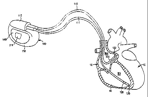
FIG. 1 is a schematic illustration of a dual chamber pacemaker implanted in a
patient's chest comprising an IPG and endocardial leads transvenously
introduced into
the right atrium and right ventricle of the heart, wherein PVC sensing can be
conducted
during the PAVEP across selected far field sensing electrode pairs;
FIG. 2 is a block diagram of the pacing IPG of FIG. 1 in which the present
invention may be practiced;
FIG. 3 is flow chart depicting the steps of a DDD pacing cycle;
FIG. 4 is a detailed flow chart depicting the steps of detecting and
responding to a
PVC sensed during the time-out of the PAVBP;
FIG. 5 is a schematic illustration of a further embodiment of a dual chamber
pacemaker implanted in a patient's chest comprising an IPG supporting a SEA
and
endocardial leads transvenously introduced into the right atrium and right
ventricle of the
heart, wherein PVC sensing can be conducted during the PAVBP across selected
far
field SEA sense electrode pairs;
CA 02515372 2005-08-05
WO 2004/071574 PCT/US2004/003270
FIG. 6 is a block diagram of the pacing IPG of FIG. 5 in which the pxesent
invention may be practiced;
FIG. 7 is a schematic illustration of a further embodiment of a dual chamber,
right and left heart pacemaker implanted in a patient's chest and endocardial
leads
5 transvenously introduced into the right atrium, right ventricle and coronary
sinus of the
heart, wherein PVC sensing can be conducted during the PAVBP across selected
right
and left heart sense electrode pairs;
FIG. 8 is a block diagram of the pacing IPG of FIG. 7 in which the present
invention may be practiced;
10 FIG. 9 is a schematic illustration of a dual chamber pacing ICD implanted
in a
patient's chest comprising an IPG and endocardial leads transvenously
introduced into
the right atrium, right ventricle, and coronary sinus of the heart supporting
pacelsense
and/or cardioversion/defibrillation electrodes, wherein PVC sensing can be
conducted
during the PAVBP across selected far field sensing electrode pairs; and
15 FIG. 10 is a block diagram of the ICD IPG of FIG. 7 in which the present
invention may be practiced.
In the following detailed description, references arc made to illustrative
embodiments of methods and apparatus for carrying out the invention. It is
understood
that other embodiments can be utilized without departing from the scope of the
invention.
FIGS. 1 and 2 depict the external configuration and components of a typical
implantable dual chamber pacemaker operating in a DDD, DDI, DDIR, or DDDR
pacing
mode or operating in an AAI or AAIR pacing mode to provide atrial pacing in
the
absence of an adequate atrial heart rate as long as ventricular sensing
indicates normal
AV conduction. Such a dual chamber IPG 100 and unipolar or bipolar atrial and
ventricular leads 114 and 116 (bipolar leads are depicted), in which the
present invention
may be implemented is depicted in FIGS. 1 and 2. The dual chamber pacemaker
IPG 100
senses and paces in the atrial and ventricular chambers, and pacing is either
triggered and
inhibited depending upon sensing of intrinsic, non-refractory atrial and
ventricular
depolarizations during the sequentially timed V-A interval and AV delay,
respectively,
as is well known in the art, in accordance with the steps set forth in the
flow chart of
FIG. 3. The pxesent invention functions when the atria are paced due to
failure to detect
CA 02515372 2005-08-05
WO 2004/071574 PCT/US2004/003270
16
atrial depolarizations or when the sensed atrial heart rate falls below a rate
dictated by a
RCP related to the need for cardiac output developed by a physiologic sensor.
In addition, the present invention can be implemented in such a dual chamber
pacing system that is incorporated into a dual chamber pacing ICD or into a
right and left
heart pacing system by itself or that is incorporated into a multi-chamber
pacing IPG.
The following description is thus intended to encompass all of the various
types of dual
chamber pacemaker systems in which the present invention can be implemented.
The IPG 100 is provided with a hermetically sealed enclosure or can 118,
typically
fabricated of bio-compatible metal such as titanium, enclosing the dual
chamber IPG
circuit 300 depicted in FIG. 2. A connector block assembly 112 is mounted to
the top of
the can 118 to receive electrical connectors located on the proximal connector
ends of
the depicted bipolar atrial and ventricular pacing leads 114 and 116.
As described further below, an electrically exposed area of the can 118
functions
as an IND CAN electrode 140 that is electrically connected to one input of a
PVC sense
amplifier to facilitate sensing of PV Cs over the heart cycle, particularly to
facilitate
sensing PVCs during the PAV~P following delivery of an A-PACE pulse.
The bipolar atrial pacing lead 116 extends between its proximal connector
coupled to
IPG 100 and distal atrial pace/sense electrodes 120 and 122 located in the
right atrium 12
of heart 10 to enable sensing of P-waves and delivery of atrial pacing pulses
to the right
atria. Atrial pacing pulses rnay be delivered between electrodes 120 and 122
in a bipolar
pacing mode or between electrode 122 and the IND~CAN electrode 140 of the IPG
100
in a unipolar pacing mode. Sensing of P-waves by the atrial sense amplifier
subject to
atrial blanking may occur between electrode 120 and electrode 122 in a bipolar
sensing
mode or between either of electrode 120 and 122 and the IND CAN electrode 140
of the
IPG 100 in a unipolar atrial sensing mode.
Similarly, the bipolar ventricular pacing lead 114 extends between its
proximal
comiector coupled to IPG 100 and distal ventricular pace/sense electrodes 128
and 130
located in the right ventricle 16 of heart 10 to both sense R-waves and to
deliver
ventricular pacing pulses to the ventricles. Ventricular pacing pulses may be
delivered
between electrodes 128 and 130 in a bipolar pacing mode or between electrode
130 and
the IND CAN electrode 140 of the IPG 100 in a unipolar pacing mode. Sensing of
R-
CA 02515372 2005-08-05
WO 2004/071574 PCT/US2004/003270
17
waves by the ventricular sense amplifier subject to blanking occurs between
electrodes
128 and 130 in a bipolar sensing mode in this preferred embodiment.
The IPG circuit 300 within IPG 100 and the bipolar atrial and ventricular
leads
114 and 116 are depicted in FIG. 2 in relation to heart 10. The IPG circuit
300 is divided
generally into a microcomputer circuit 302 and a pacing input/output circuit
320. The
input/output circuit 320. includes the digital controller/timer circuit 330,
the atrial and
ventricular pacing pulse output circuit 340 and the atrial and ventricular
sense amplifiers
circuit 360, as well as a number of other components and circuits described
below. The
digital controller/timer circuit 330 provides control of timing and other
functions within
the input/output circuit 320. Digital controller/timer circuit 330, operating
under the
general control of the microcomputer circuit 302, includes a set of timing and
associated
logic circuits, of which certain ones pertinent to the present invention are
depicted and
described further below.
Preferably, the IPG 100 or one of the leads 114 or 116 includes one or more
physiologic sensor that develops a physiologic signal that relates to the need
for cardiac
output. The use of physiologic sensors to provide variation of pacing rate in
response to
sensed physiologic parameters, such as physical activity, oxygen saturation,
blood
pressure and respiration, has become commonplace.
Commonly assigned LT.S. Patent I~Tos. 4,428,378 and 4,890,617 disclose
activity
sensors that are employed to vary the pacing escape interval in single and
dual chamber
pacemaker IPGs in response to sensed physical activity. Such an activity
sensor 316 is
coupled to the inside surface of the IPG hermetically sealed enclosure 118 and
may take
the form of a piezoelectric crystal transducer as is well known in the art.
The activity
sensor 316 generates an output signal in response to certain patient
activities, e.g.
ambulating, that is processed and used as a rate control parameter (RCP). If
the IPG
operating mode is progranuned to a rate responsive mode, the patient's
activity level
developed in the patient activity circuit (PAS) 322 is monitored, and a sensor
derived V-
A, A-A or V-V escape interval is derived proportionally thereto. A timed
interrupt, e.g.,
every two seconds, may be provided in order to allow the microprocessor 304 to
analyze
the output of the activity circuit PAS 322 and update the basic V-A (or A-A or
V-V)
escape interval employed to govern the pacing cycle and to adjust other time
intervals as
described below.
CA 02515372 2005-08-05
WO 2004/071574 PCT/US2004/003270
18
The bipolar leads 114 and 116 are illustrated schematically with their
associated
pace/sense electrode sets 120, 122 and 128, 130, respectively, as coupled
directly to the
atrial and ventricular pacing pulse output circuit 340 and sense amplifiers
circuit 360 of
pacing circuit 320. The atrial and ventricular pacing pulse output circuit 340
and sense
amplifiers circuit 360 contain pulse generators and sense amplifiers
corresponding to any
of those presently employed in commercially marketed cardiac pacemakers for
atrial and
ventricular pacing and sensing.
Sense amplifiers circuit 360 also comprises a PVC sense amplifier coupled with
the IND CAN electrode 140 and one of the ventricular pace/sense electrodes 128
or 130
selected by a ventricular select (V-SELECT) signal so that PVCs can be sensed
along a
bipolar or far-field sense vector. It will be understood that other sense
electrodes can be
coupled to the PVC sense amplifier within the sense amplifiers circuit 360 and
selected
by an appropriate V-SELECT signal through programming commands in the course
of a
telemetry session.
Sensitivity settings of the atrial and ventricular sense amplifiers and the
PVC
sense amplifier in sense amplifiers circuit 360 can be programmed by the
physician to
reliably sense true P-waves, 12-waves and PVCs during a patient work-up at
implantation
or during a patient follow-up telemetry session. Digital controller/timer
circuit 330
controls the sensitivity settings of the atrial and ventricular sense
amplifiers in sense
amplifiers circuit 360 by means of sensitivity control 350.
The depicted counters and timers within digital controller/timer circuit 330
include AEP and VEP timers 366, intrinsic interval timers 368 for timing
average
intrinsic A-A and V-V intervals from A-EVENTS and V-EVENTS, escape interval
timers
370 for timing A-A, V-A, and/or V-V pacing escape intervals, an AV delay timer
372 for
timing the SAV delay from a preceding A-EVENT or PAV delay from a preceding A-
TRIG, refractory period timers 374 for timing ARP, PVARP and VRP times and a
PVC
flag register 376 that is set upon detection of a PVC. Digital
controller/timer circuit 330
starts and times out these intervals and time periods that are calculated by
microcomputer
circuit 302 for controlling the above-described operations of the atrial and
ventricular
sense amplifiers in sense amplifiers circuit 360 and the atrial and
ventricular pace pulse
generators in output amplifier circuit 340.
CA 02515372 2005-08-05
WO 2004/071574 PCT/US2004/003270
19
In order to trigger generation of a V-PACE pulse, digital controller/timer
circuit
330 generates a V-TRIG signal at the end of a PAV or SAV delay provided by AV
delay
timer 372. Similarly, in order to trigger an atrial pacing or A-PACE pulse,
digital
controller/timer circuit 330 generates an A-TRIG signal at the termination of
the V-A
interval timed out by escape interval timers 370.
The ABP and VBP timers 366 of digital controller/timer circuit 330 time out
the
above-described PAVBP and PAABP during and following an A-PACE pulse and the
PAVBP and PVVBP during and following a V-PACE pulse. Thus, an atrial blanking
(A-
BLANK) signal is applied to the atrial sense amplifier for the prevailing ABP,
and a
ventricular blanking (V-BLANK) signal is applied to the ventricular sense
amplifier for
the prevailing VBP. In the absence of an A-BLANK signal, atrial
depolarizations or P-
waves that are detected by the atrial sense amplifier result in an A-EVENT
that is
communicated to the digital controller/tirner circuit 330. Similarly, in the
absence of a V-
BLANK signal, ventricular depolarizations or R-waves that are detected by the
ventricular sense amplifier result in a V-EVENT that is c~mmunicated to the
digital
controller/timer circuit 330. In accordance with the present invention, the
PVC sense
amplifier within sense amplifiers circuit 360 is only blanked during delivery
~f the A-
PACE pulse t~ prevent the delivered A-PACE pulse from either damaging the
sense
amplifier circuitry or being incorrectly sensed as a PVC.
The refractory period timers 374 time the ARP fr~m an A-TRIG pulse or A-
EVENT during which a sensed A-EVENT is ignored for the purpose of resetting
the V-
A interval. The ARP extends from the beginning of the SAV or PAV interval
following
either an A-EVENT or an A-TRIG and until a predetermined time following a V-
EVENT or a V-TRIG. The refractory period timers 374 also time the PVARP from a
V-
TRIG pulse or V-EVENT during which a sensed A-EVENT is also ignored for the
purpose of resetting the V-A interval. The VRP is also be timed out by the
refractory
period timers 374 after a V-EVENT or V-TRIG signal so that a subsequent,
closely
following V-EVENT is ignored for the purpose of restarting the V-A interval
and setting
the PVC flag in register 366.
The base ARP, PVARP and VRP that prevails at the lower rate of 60 - 70 bpm,
for example, are either default or programmed parameter values stored in the
microcomputer 302. These refractory period parameter values can be fixed for
the full
CA 02515372 2005-08-05
WO 2004/071574 PCT/US2004/003270
operating range of pacing rates between the programmed lower rate and the URL,
which
may be 120 bpm, for example, or they can be programmed to follow the algorithm
for
automatically shortening in duration as the paced or intrinsic heart rate
increases to
ensure that the long refractory periods during the diminishing escape
intervals do not
5 prevent delivery of ventricular pacing pulses synchronized to valid
intrinsic P-waves.
The A-EVENT is characterized as a refractory A-EVENT if it occurs during
time-out of an ARP or a PVARP or a non-refractory A-EVENT if it occurs after
time-out
of these atrial refractory periods. Similarly, a V-EVENT is characterized as a
refractory
V-EVENT if it occurs during time-out of a VRP or a non-refractory V-EVENT if
it
10 occurs after time-out of the ventricular refractory period. Refractory A-
EVENTs and V-
EVENTS are typically ignored for purposes of resetting timed out AV delays and
V-A
intervals, although diagnostic data may be accumulated related to their
occurrences.
Microcomputer 202 contains a microprocessor 304 and associated system clock
308 and on-processor RAM and ROM chips 310 and 312, respectively. In addition,
15 microcomputer circuit 302 includes a separate RAM/R~M chip 314 to provide
firmware
and additional RAM memory capacity. Microprocessor 304 is interrupt driven,
operating
in a reduced power consumption mode normally, and awakened in response to
defined
interrupt events, which may include the A-TRIG, V-TRIG, A-EVENT and V-EVENTS.
Microcomputer 302 controls the operational functions of digital
controller/timer
20 324, specifying which timing intervals are employed in a programmed pacing
mode via
data and control bus 306. The specific values of the intervals timed by the
digital
controller/timer circuit 330 are controlled by the microcomputer circuit 302
by means of
data and control bus 306 from programmed-in parameter values. The
microcomputer 302
also calculates the RCP derived or intrinsic atrial rate derived V-V, A-A or V-
A interval,
tlxe variable AV delay, and the variable ARP, PVARP and VRP. Typically, the AV
delay
in modern VDD, VDDR, DDD and DDDR pacemakers is either fixed or varies with
the
prevailing intrinsic atrial rate, measured as an A-A interval, and/or varies
as a function of
a physiologic sensor derived pacing rate.
Digital controller/timer circuit 330 also interfaces with other circuits of
the input
output circuit 320 or other components of IPG circuit 300. Crystal oscillator
circuit 338
provides the basic timing clock and battery 318 provides power for the pacing
circuit 320
and the microcomputer circuit 302. Power-on-reset circuit 336 responds to
initial
CA 02515372 2005-08-05
WO 2004/071574 PCT/US2004/003270
21
connection of the circuit to the battery 318 for defining an initial operating
condition and
similarly, resets the operative state of the IPG circuit 300 in response to
detection of a
low battery condition. Reference mode circuit 326 generates stable voltage
reference and
currents for the analog circuits within the pacing circuit 320. ADC (analog to
digital
converter) and multiplexer circuit 328 digitizes analog signals and voltage to
pxovide real
time telemetry of cardiac signals from sense amplifters 360, for uplink
transmission via
RF transmitter and receiver circuit 332. Voltage reference and bias circuit
326, ADC and
multiplexer 328, power-on-reset circuit 336 and crystal oscillator circuit 338
may
correspond to any of those presently used in current marketed implantable
cardiac
pacemakers.
Data transmission to and from an extexnal programmer (not shown) during a
telemetry session is accomplished by means of the telemetry antenna 334 and an
associated RF transmitter and receiver 332, which series both to demodulate
received
downlink telemetry and to transmit uplink telemetry. IJplink telemetry
capabilities will
typically include the ability to transmit stored digital information, e.g.
operating modes
and parameters, EGM histograms, and othex events, as well as real time EGMs of
atrial
and/or ventricular electrical activity and Marker Channel pulses indicating
the
occurrence of sensed and paced dep~larizations in the atrium and ventricle, as
are well
known in the pacing art.
' Reed switch 317 when closed by application of a magnetic field may be
employed to enable pr~gramming of the pacemaker and also may be employed to
convert the pacemaker temporarily to an asynchronous pacing mode such as D~~
or
VOO. Qperation in the asynchronous mode may continue as long as the magnetic
field is
present, may continue until overridden by the programmer or may continue for a
pre-set
time period.
The illustrated IPG circuit 300 of FIG. 2 is merely exemplary, and corresponds
to
the general functional organization of most multi-programmable microprocessor
controlled DDD and DDDR cardiac pacemaker IPGs presently commercially
available.
It is believed that the present invention can readily be practiced using the
basic hardware
and software of existing microprocessor controlled, dual chamber pacing
systems that
are incorporated into dual chamber pacemakers or into ICDs or into right and
left heart
pacing systems. The invention is preferably implemented into the exemplary
pacing
CA 02515372 2005-08-05
WO 2004/071574 PCT/US2004/003270
22
system by means of modifications to the hardware incorporating the PVC sense
amplifier
to detect signals across a PVC sense vector during the PAVBP and at other
times during
the pacing cycle and to declare a PVC if the signal (regardless of its true
source) satisfies
PVC detection criterion. In addition, software stored in the ROM 310 of the
microcomputer circuit 302 responding to such detected PVCs is modified as
described
further below. However, the operating functions of the present invention may
also be
usefully practiced by means of a full custom integrated circuit, for example,
a circuit
taking the form of a state machine, in which a state counter serves to control
an
arithmetic logic unit to perform calculations according to a prescribed
sequence of
counter controlled steps.
FIG. 3 is a functional flow chart of the overall pacing cycle timing operation
of
the pacemaker IPG circuit 300 illustrated in FIG. 2 in the DDD or DDDR pacing
modes.
In the flow chart of FIG. 3, it is assumed that the A-A or V-V escape
interval, cardiac
cycle timing of the IPG circuit 300 ranges between a programmed lower rate and
a
programmed LTRL, and is based on the definition of a V-A interval and an AV
delay,
specifically either the SAV or the PAV delay interval. The AV delay and V-A
interval of
any given pacing cycle may be determined as a function of a sensor-derived V-A
interval
or an atrial rate based V-A interval determined by the average measured
intrinsic A-A
atrial rate if it is stable and varies between the programmed lower rate and
LTRL. In this
particular embodiment, separate SAV and PAV delays axe deftned, although in
practice
they may have the same duration. The operations of the flow chart may also
incorporate
any of the mode switching and sinus preference algorithms of the prior art
described
above to switch between the use of the sensor ox the atrial rate derived
escape intervals.
However the algorithm is specifically implemented, it is understood to
incorporate the
PVC response algorithm of the present invention as described hereafter.
Fox convenience, the pacing cycle is assumed to begin at step S 100 starting
from
a non-refractory A-EVENT. Timing of the prevailing SAV delay and ARP are
commenced in step S 100, and the system awaits either time out of the SAV
delay in step
S 102 or a non-refractory V-EVENT in step S 104. Neither of the atrial and
ventricular
sense amplifters is blanked, and the PVC sense amplifier may also be enabled.
A V-
TRIG and the associated A-BLANK and V-BLANK signals are generated at step 5106
at
CA 02515372 2005-08-05
WO 2004/071574 PCT/US2004/003270
23
the end of the SAV delay if a non-refractory V-EVENT does not occur at step S
104 prior
to SAV time-out in step S 102.
The SAV delay is terminated without delivery of a V-PACE pulse if either of a
PVC or a V-EVENT is declared or if both a PVC and a V-EVENT are declared in
step
S 124, and the V-A interval is restarted in step S 108. The redundant sensing
of PVCs or
other signals by the PVC sense amplifier and the near field R-wave sense
amplifier
during time-out of the SAV delay provides a robust sensing capability that
increases
confidence that unnecessary pacing of the ventricles is avoided.
The V-A interval time-out is commenced in step 5108, and time-out of the post
ventricular time periods including the VRP, PVARP, PAVBP and PVVBP are
commenced in step 5110. The algorithm awaits expiration of the V-A interval at
step
5112, and it is possible that a refractory or non-refractory A-EVENT or V-
EVENT can
occur during the V-A interval time-out.
If a non-refractory A-EVENT is sensed in step S 120 during time-out the V-A
interval, the V-A interval is terminated, the AV delay is set to the SAV delay
in step
S 124, and the SAV delay and associated post atrial sense ARP is timed out in
step S 100.
~ptionally, the non-refractory A-EVENT also causes the V-A interval to be
measured by
intrinsic interval timer 368 and employed to derive or update the intrinsic
atrial rate that
is saved in RAIN. The V-A interval, the SAV and PAV delays, the PVARP, and the
pacing escape interval for the next cardiac cycle can then be recalculated in
dependence
upon either the updated average A-A interval or upon the RCP in a manner well
known
in the art.
If a non-refractory V-EVENT is declared sensed by the near field or bipolar
ventricular sense amplifier at step 5122 during time out of the V-A interval
in the
absence of detection of a preceding A-EVENT, then the declared V-EVENT is
characterized as a PVC in step 5124. It should be noted that such a
declaration of a V-
EVENT during the V-A interval can be confirmed by the declaration of a PVC by
the
PVC sense amplifier. Certain algorithms, e.g., those disclosed in the above-
referenced
'088 patent, have been devised to deal with such PVCs occurring during the V-A
interval
that could be practiced along with but are not necessary to the practice of
the present
invention.
CA 02515372 2005-08-05
WO 2004/071574 PCT/US2004/003270
24
An A-TRIG signal is generated in step S 114 at the time-out of the V-A
interval if
the V-A interval times out without sensing any such intervening non-refractory
A-
EVENT or V-EVENT. In this case, the next succeeding AV delay is defined to be
equal
to PAV at step 5116, and the PAV is timed out in step 5118 along with the
associated
VSP delay and the ARP, ABP and PAVBP in accordance with the steps of FIG. 4.
The
particular algorithm of FIG. 4 assumes that a VSP function is provided and
that the VSP
delay is timed out in timers 366 whenever a V-PACE is delivered, but the
present
invention can be practiced without the VSP function being present or
programmed on in
a particular case. Moxeover, the algorithm of FIG. 4 assumes that the PVC
sense
amplifier. is always enabled, but the PVC sense amplifier could be blanked or
disabled
during delivery of the A-PACE pulse and V-PACE pulse.
The time-out of the PAV delay is monitored in step S 128, and a V-PACE pulse
is
delivered in step 5138 if the PAV delay does time-out without declaration of
either of a
PVC or a V-EVENT. In step 5130, a PVC can be declared at any time during the
PAV
delay and a V-EVENT can be declared following the time-out of the PAVBP. If
the VSP
function is not present or programmed ~N as determined in step S 132, then
such a
declared PVC or V-EVENT would simply cause the V-A interval to commence in
step
5108.
however, preferably the VSP function is employed as determined in step S 132,
and a declared PVC ox ~V-EVENT causes the V-A interval to comanence in step
5108
only if it is declared after time-out of the VSP delay. If a PVC or V-EVENT is
declared
in step 5130 before time-out of the VSP delay, then a V-PACE is delivered in
step 5140
at time-out of the VSP delay.
To enable this function, a VSP flag is set in step 5136 if a PVC ox V-EVENT is
declared in step 5130 before time-out of the VSP delay as determined in step
5134. The
status of the VSP flag is checked in step 5138 when the VSP delay does time-
out as
determined in step 5134. Since the VSP flag was set in this instance in step
5136, then
the V-PACE pulse is delivered at time-out of the VSP delay. In this way, a PVC
that
would otherwise not be detected during the PAVBP does trigger the VSP function
to
pace the ventricles within a safe time from the PVC and not within the
vulnerable period
of the heart.
CA 02515372 2005-08-05
WO 2004/071574 PCT/US2004/003270
If a PVC or V-EVENT is declared in step 5130 after time-out of the VSP delay,
as determined in step 5134, then a V-PACE is not delivered in step 5140. The
time-out
i
of the PAV delay is terminated, and the V-A interval is started in step 5108.
The
redundant sensing of PVCs or other signals by the PVC sense amplifier and the
near field
5 R-wave sense amplifier in the time period between the end of the VSP delay
and the
time-out of the PAV delay provides a robust sensing capability that increases
confidence
that unnecessary pacing of the ventricles is avoided.
The PVC sense amplifier of the depicted embodiment of FIGS. 1 and 2 senses the
far field R-wave to particularly detect PVCs across the sensing vector
comprising the
10 IND CAN electrode 10 and one of the ring and tip ventricular pace/sense
electrodes 128
and 130. It is expected that the PVC sense amplifier could be advantageously
coupled to
the 1ND CAN electrode 10 and the ring pace/sense electrode 128 because it may
not be
in the blood and not in contact with endocardial surface resulting in a wide
QRS
complex., It will be understood from the following that other far field
sensing vectors can
15 be selected depending on the available sensing electrodes of the pacing or
cardioversion/defibrillation system. The PV C sense amplifier sensitivity can
be
programmed in a telemetry session to sense intrinsic R-waves appearing in a
conventional ECG display. The PVC sense amplifier's uplink telemetered
response (the
presence or absence of a PVC output signal) can be observed simultaneously.
The PVC
20 sense amplifier sensitivity can be varied for each programmed PVC sense
vector, and the
PVC sense vector providing the best consistent detection of R-waves can be
determined.
A "permanent" V-SELECT can then be programmed for coupling the P VC sense
amplifier inputs to receive the optimal pair of signals across the PVC sense
electrodes
during chronic implantation.
25 The present invention including the steps of FIGS. 3 arid 4, can be
practiced in a
dual chamber pacemaker of the type depicted in FIGS. 5 and 6 comprising an IPG
100'
supporting a SEA on the IPG housing comprising at least one pair of sense
electrodes
whereby a sense vector or sense vectors can be defined between the sense
electrodes.
The IPG 100' and IPG circuit 300' conform in most ways to the IPG 100 and IPG
circuit
300 described above in reference to FIGS. 1 and 2 with the addition of the
SEA.
Preferably, the SEA comprises at least three or four orthogonally disposed
sense
electrodes or more than four sense electrodes disposed around the IPG housing
including
CA 02515372 2005-08-05
WO 2004/071574 PCT/US2004/003270
26
the IPG connector block and the hermetically sealed enclosure. In the depicted
example,
the SEA comprises sense electrodes 142, 144, and 146 with sense electrode 146
disposed
either on the IPG connector block 112' or the IPG hermetically sealed housing
118'. As
in the embodiment of FIGS. 1 and 2, endocardial leads 114 and 116
transvenously
introduced into the right atrium 12 and right ventricle 16 of the heart 10.
The IPG circuit
300' can select the optimal sensing vector sensed by the PVC sense amplifier
within a
sense amplifiers circuit 360' by an appropriate V-SELECT command operating
additional PVC sense amplifier input switching circuitry of the type disclosed
in the
above-referenced ' 966 patent.
The sense electrodes 142, 144, and 146 or the SEA are situated on the IPG
housing comprising the connector block 112' and/or the hermetically sealed
enclosure
118' so to at least four sense vectors that are characterised as far field
sense vectors
because the SEA is located subeutaneously remote from the heart 10. The SEA
provides
thxee or four far field PVC sense vectors comprising PVC sense vector A - B
between
sense electrodes 146 and 144, PVC sense vector B - C between sense electrodes
144 and
142, and PVC sense vector A - C between sense electrodes 142 and 146 by
appropriately
coupling the input signals A, B, and C to the PVC sense amplifier inputs
within sense
amplifiers circuit 360'. A fourth PVC sense vector B - (C - A) can be
mathematically
derived from the input signals A, B and C, but the simpler selection of a pair
of input
signals among signals A, B, and C may well suffice in practice and will be
assumed in
the following description.
The optimal far field sense vector for sensing an R-wave, and, by logical
extension, for sensing PVCs occurring during the PAVBP can be determined
following
implantation of the IPG 100' and the leads 114 and 116 in the patient's body.
The
sensitivity of the PVC sense amplifier and the V-SELECT pairing signals A, B,
and C
can both be temporarily programmed in a telemetry session with an external
programmer, and the IPG 100' can be commanded to uplink telemeter the PVC
sense
signal. The intrinsic R-waves and any spontaneously occurring PVCs appearing
in a
conventional ECG display and the PVC sense amplifier's uplink telemetered
response
can be observed simultaneously. The PVC sense amplifier sensitivity can be
varied for
each programmed far field sense vector, and the sense vector providing the
best
consistent detection of R-waves with the best ventricular sense safety margin
can be
CA 02515372 2005-08-05
WO 2004/071574 PCT/US2004/003270
27
determined. Other comparative tests to determine the optimal PVC sense vector
could
include simply measuring the R wave amplitude, the R wave width, and slew
rates
through the PVC sense amplifier and determining the optimal PVC sense
amplifier
through comparison of one or a combination of these parameters of the sensed R-
waves.
Or comparative testing can be conducted varying a blanking period applied to
the PVC
sense amplifier to determine the PVC sense vector across which an R-wave can
be
sensed at the longest blanking period. A "permanent" V-SELECT can then be
programmed for coupling the PVC sense amplifier inputs to receive the optimal
pair of
signals A, B, C during chronic implantation.
The chronic operation of the selected far field PVC sense vector can be
determined in a telemetry session initiated at a later time from data
accumulated in
mem~ry registers indicating the number ~f times that a PVC was detected during
the
PAVBP and the delivery of a V-PACE was inhibited at time-out of the PAV delay.
In
IPGs having the VSP function, the saved data would comprise the number of
times that a
PVC was detected during the PAVBP and/or before time-out of the VSP delay, and
the
delivery of a V-PACE pulse at time-out of the VSP delay.
In a similar way, optimal PVC sense vectors can be selected in a dual chamber
pacing systems pr~viding right and left heart chamber pacing and sensing of
the type
described in commonly assigned ZJS-A-6,477,415. Such mufti-chamber pacing
systems
provide right and left atrial and/or ventricular pacing and sensing
particularly to enhance
cardiac output of hearts in heart failure. In such a right and left heart
pacing context
providing atrial pacing, the PVC sense electrode pair can comprise right and
left heart
chamber pace/sense electrodes defining an optimal R-wave sense vector ox can
additionally comprise one of the left heart chamber pace/sense electrodes and
the
indifferent electrode supported on or comprising the conductive IPG can
defining an
optimal PVC sense vector.
Such a right and left heart pacing system comprising endocardial RV lead 114,
RA lead 116, and a CS lead 150 transvenously introduced into the right
ventricle 16, the
right atrium 12, and the coronary sinus, respectively of the heart 10 and
coupled to the
connector block 112" of the IPG 100"' is depicted in FIGS. 7 and 8. The
depicted CS
lead 150 supports an LV pace/sense electrode 154 disposed in the CS or a
coronary vein
CA 02515372 2005-08-05
WO 2004/071574 PCT/US2004/003270
28
descending from the CS in operative relation to the,LV and an LA pace/sense
electrode
152 disposed in the CS in operative relation to the LA.
Pacing and sensing in the RA and RV one or both of the LA and LV can be
conducted in the manner described in the above-referenced '415 patent. The
components
of the IPG circuit 300"' correspond in large part with the components of the
IPG circuit
300 described above. The flow charts of FIGS. 3 and 4 are followed, and right
and left
heart pacing pulses can be delivered simultaneously or with a delay as
determined in
block 364 of digital controller/timer circuit 330. The output amplifiers
circuit 340' can
deliver the depicted RA-PACE, LA-PACE, RA-PACE and RV-PACE pulses through
selected pace/sense electrode pairs or employing the can electrode 140 as an
indifferent
pacing electrode.
Similarly, the sense amplifters circuit 360' includes the respective atrial
and
ventricular sense amplifiexs for declaring an LA-EVENT, an RA-EVENT, an LV-
EVENT ox an RV-EVENT through selected pace/sense electrode pairs or employing
the
can electrode 140 as an indifferent sense electrode.
A PVC sense vector can be defined by an appropriate V-SELECT command
through pacc/sense electrode selection and control circuit or registers 350'.
In this
embodiment illustrated in FIGS. 7 and 8, the PVC sense vector can be selected
by an
appropriate V-SELECT command among: (1) the can electrode 140 and the RV ring
pace/sense electrode 128; (2) the can electrode 140 and the LV pace/sense
electrode 154;
(3) the LA pacc/sense electrode 152 and the LV pace/sense electrode 154; (4~)
the LA
pace/sense electrode 1 S2 and the RV ring pace/sensc electrode 128; and (5)
the RV ring
pace/sense electrode 128 the LV pace/sense electrode 154 depicted as PVC sense
vector
160 in FIG. 7. The selection can be made employing comparative testing of the
PVC
sense electrode pairs as described above.
In a similar way, PVC sense vectors can be selected in a dual chamber pacing
ICD implanted in a patient's chest comprising an ICD IPG and endocardial leads
transvenously introduced into the right atrium, right ventricle, and coronary
sinus of the
heart bearing pace/sense and/or cardioversion/defibrillation electrodes,
wherein PVC
sensing can be conducted during the PVAB period across selected far field PVC
sense
electrode pairs. The dual chamber ICD can also be configured to provide right
and left
CA 02515372 2005-08-05
WO 2004/071574 PCT/US2004/003270
29
heart pacing and/or have at lease one SEA electrode provided with the as in
the
embodiments of FIGS. 5 - 8.
FIGS. 9 and 10 illustrate a dual chamber, multi-programmable, ICD IPG 400 and
associated lead system for providing atrial and/or ventricular sensing
functions for
detecting P-waves of atrial depolarizations and/or R-waves of ventricular
depolarizations, depending on the programmed pacing and/or sensing mode and
delivering pacing or cardioversion/defibrillation therapies. An exemplary
cardioversioi~/deribrillation lead system is depicted in FIG. 9 for delivering
cardioversion/defibrillation shock therapies to the atria or ventricles of the
heart. FIGS. 9
and 10 are intended to provide a comprehensive illustration of each of the
atrial and/or
ventricular, pacing and/or cardioversion/defibrillation configurations that
may be
effected using sub-combinations of the components depicted therein and
equivalents
thereto. The present invention can be implemented into such ICDs wherein the R-
wave
sense amplirier is normally blanked during a PAVBP following delivery of an A-
PACE
pulse.
In the preferred eanbodiment of FIGS. 9 and 10, depending on the programmed or
current pacing mode, pacing pulses are applied to the atrium and/or ventricle
in response
to the detection of the appropriate bradycardia condition by the ICD IPG
operating
system. The pacing and sensing functions are effected through atrial and
ventricular
bipolar pace/sense electrode pairs at the ends of right atrial/superior vane
cave
(RA/SVC) and right ventricular (RV) leads 440 and 416, respectively, axed in
the right
atrium 12 and right ventricle 16, respectively, that are electrically coupled
to the circuitry
of IPG 400 through a connector block 412. Delivery of cardioversion or
defibrillation
shocks to the atrial and/or ventricular chambers of the heart 10 may be
effected through
selected combinations of the illustrated exemplary RA and RV
cardioversion/defibrillation electrodes on the RA/SVC and RV leads and an
additional
coronary sinus (CS) electrode on a CS lead 430 as well as an exposed surface
electrode
410 of the outer housing or can of the IPG 400. The can electrode 410
optionally serves
as a subcutaneous cardioversion/defibrillation electrode, used as one
electrode optionally
in combination with one intracardiac cardioversion/defibrillation electrode
for
cardioverting or defibrillating either the atria or ventricles. A remote,
subcutaneous
CA 02515372 2005-08-05
WO 2004/071574 PCT/US2004/003270
defibrillation patch electrode may be provided in addition to or substitution
for the can
electrode 410.
The RV lead 416 is depicted in a conventional configuration and includes an
elongated insulating lead body, enclosing three concentric, electrically
isolated, coiled
5 wire conductors, separated from one another by tubular insulating sheaths.
Located
adjacent the distal end of the RV lead 416 are a pace/sense ring electrode
424, a helical,
pace/sense electrode 426, mounted retractably within an insulating electrode
head 428.
Helical electrode 426 is adapted to be extended out of the electrode head 428
and
screwed into the ventricular apex in a manner well known in the art. RV
pace/sense
10 electrodes 424 and 426 are each coupled to a coiled wire conductor within
the RA lead
body and are employed for cardiac pacing in the ventricle and for sensing near-
field R-
waves. RV lead 416 also supports an elongated, exposed wire coil,
cardioversion/defibrillation electrode 422 in a distal segment thereof adapted
to be
placed in the right ventricle 16 of heart 10. The RV
cardioversion/defibrillation electrode
15 422 may be fabricated fr~m platinum, platinum alloy or other materials
known t~ be
usable in implantable cardi~version/defibrillation electrodes and may be about
5 cm in
length. cardioversion/defibrillation electrode 422 is also coupled to ~ne of
the coiled wire
conduct~rs within the lead body of RV lead 416. At the pr~ximal end of the
lead b~dy is
a bifurcated connector end 418 having three exposed electrical connectors,
each coupled
20 to one of the coiled conductors that are attached within the connector
block 412 to
connect~x bl~ck terminals in a manner well known in the art.
The cor~nary sinus (CS) lead 430 includes an elongated insulating lead b~dy
enclosing one elongated coiled wire conductor coupled to an elongated exposed
coil wire
cardioversion/defibrillation electrode 434. CS cardioversion/defibrillation
electrode 434,
25 illushated in broken outline, is located within the coronary sinus and
great vein 408 of
the heart 10 and may be about 5 cm in length. At the proximal end of the CS
lead 430 is
a comiector end 432 having an exposed connector coupled to the coiled wire
conductor
and attached within the connector block 412 to coimector block terminals in a
manner
well known in the art.
30 The RA/SVC lead 440 includes an elongated insulating lead body carrying
three
concentric, electrically isolated, coiled wire conductors separated from one
another by
tubular insulating sheaths, corresponding generally to the structure of the RV
lead 416.
CA 02515372 2005-08-05
WO 2004/071574 PCT/US2004/003270
31
The lead body is formed in a manner well known in the art in an atrial J-shape
in order to
position its distal end in the right atrial appendage. A pace/sense ring
electrode 444 and
an extendable helical, pace/sense electrode 446, mounted retractably within an
insulating
electrode head 448, are formed distally to the bend of the J-shape. Helical
electrode 446
is adapted to be extended out of the electrode head 448 and screwed into the
atrial
appendage in a mariner well known in the art. RA pace/sense electrodes 444 and
446 are
employed for atrial pacing and for near-field sensing of P-waves. An
elongated, exposed
coil defibrillation RA/SVC electrode 450 is supported on R.A lead 440
extending
proximally to pace/sense ring electrode 444 and coupled to the third coiled
wire
conductor within the RA lead body. Electrode 450 preferably is 40 cm in length
or
greater and is configured to extend from within the SVC and toward the
tricuspid valve.
At the proximal end of the RA lead 440 is a bifuxcated connector 442 which
carries three
exposed electrical connectors, each coupled to one of the coiled wire
conductoxs, that are
attached within the connector block 412 to connector block terminals in a
manner well
known in the art.
Preferably, bipolar pace/sense electrodes 444, 446 and 424, 426 are employed
for
near field sensing and for delivery of pacing pulses to the atria and
ventricles. The
configuration, manner of fixation, and positioning of bipolar pace/sense
electrodes 444,
446 and 424, 426 with respect to the atria and ventricles, respectively, may
differ fiom
those shown in FIG. 9. TJnipolar pace/sense electrode bearing leads may also
be used in
the practice of the invention, and the second, retuxn electrode may be one or
more of the
cardioversion/defibrillation electrodes or the can electrode 410.
The ICD system configuration and operating modes of FIG. 9 may be varied by
eliminating: (1) the atrial or ventricular cardioversion/defibrillation
capability and
associated lead and electrodes while retaining the dual chamber pacing and
sensing
capability thereby providing single chamber cardioversion/defibrillation and
dual
chamber bradycardia/tachycardia pacing capabilities; or (2) in a special case
of an atrial
ICD, the ventricular cardioversion/defibrillation capability while retaining
at least the
atrial pace/sense capability and the ventricular sense capability for
providing R-wave
synchronization of the delivered atrial cardiovexsion therapies. In each such
system, it
will be understood that appropriate defibrillation and pacing leads will be
employed in
the system. In a simpler ICD system employing only the IPG can electrode 410
or a
CA 02515372 2005-08-05
WO 2004/071574 PCT/US2004/003270
32
cardioversion/defibrillation electrode implanted subcutaneously and more
remote from
the heart chamber and only one the other of the cardioversion/defibrillation
electrode
located in proximity to the atrium or ventricle, e.g. electrodes 422 or 450,
then it is
desirable to couple the PVC sense amplifier inputs to the available
S cardioversion/defibrillation electrodes.
FIG. 10 is a functional schematic diagram of the circuitry of a dual chamber,
ICD
400 in which the present invention may usefully be practiced. The circuitry of
FIG. 10
should be taken as exemplary of a dual chamber ICD IPG 400 in which the
invention
may be embodied, and not as limiting, as it is believed that the invention may
usefully be
practiced in a wide variety of device implementations, as long as a dual
chamber pacing
mode providing bradycardia pacing therapies to the atria is retained that
involve blanking
of the ventricular sense amplifier.
The ICD IPG circuitry of FIG. 10 includes a high voltage section for providing
relatively high voltage cardioversion/defibrillation shocks when needed in
response to
detection of a tachyarrhythmia, a low voltage pace/sexxse section for sensing
P-waves
and/or R-waves and providing relatively low voltage bradycardia pacing and an
ti-
tachycardia pacing therapies, both operated under the control of a
microcomputer
including a microprocessor 224, ROM/RAM 226 and DMA 228. Other functions,
including uplink and downlink telemetry with an external programmer for
interrogating
or programming operating modes and parameters, are also provided (but not
shown) in a
manner well known in the art.
The block diagram of FIG. 10 depicts the atrial and ventricular pace/sense and
defibrillation lead connector terminals of the connector block 412. Assuming
the
electrode configuration of FIG. 9, the correspondence to the illustrated leads
and
electrodes is as follows: Optional terminal 310 is hard wired to can electrode
410, that is,
the un-insulated portion of the housing of the ICD IPG 400, and technically
may be
directly connected and not be part of the connector block 412. Terminal 320 is
adapted to
be coupled through RV lead 416 to RV cardioversion/
cardioversion/defibrillation
electrode 422. Terminal 311 is adapted to be coupled through RA lead 440 to
RAJSVC
electrode 450. Terminal 318 is adapted to be coupled through CS lead 430 to CS
cardioversion/defibrillation electrode 434. However, it will be understood
that fewer
terminals may be provided than depicted, and/or that one or more differing
defibrillation
CA 02515372 2005-08-05
WO 2004/071574 PCT/US2004/003270
33
leads, e.g. epicardial patch electrode and subcutaneous patch electrode
bearing leads may
also be employed for one or more of the depicted cardioversion/defibrillation
electrode
bearing leads.
Terminals 310, 311, 318 and 320 are coupled to high voltage output circuit
234.
High voltage output circuit 234 includes high voltage switches controlled by
CV/DEFIB
CONTROL logic 230 via control bus 238. The switches within circuit 234 control
which
electrodes are employed and which are coupled to the positive and negative
terminals of
the capacitor bank including capacitors 246 and 248 during delivery of the
intermediate
and high voltage cardioversion and defibrillation shocks.
Terminals 324 and 326 of the connector block are adapted to be coupled through
RV
lead 416 to RV pacelsense electrodes 424 and 426 for sensing and pacing in the
ventricle. Terminals 317 and 321 are adapted to be coupled through RA/SVC lead
440 to
RA pace/sense electrodes 444 and 446 for sensing and pacing in the atrium.
Terminals
324 and 326 are coupled to the inputs of R-wave sense amplifier 200 through
switches in
switch network 208. R-v~ave sense amplifier 200, which preferably takes the
form of an
automatic gain contr~lled amplifier providing an adjustable sensing thresh~ld
as a
function of the measured R-wave signal amplitude. A VSENSE signal is generated
on R-
O~(TT line 202 whenever the signal sensed between electrodes 4~24~ and 426
exceeds the
current ventricular sensing threshold.
Terminals 317 and 321 are coupled t~ the P-wave sense amplifier 204 through
switches in switch network 208. P-wave sense amplifier 204 preferably also
takes the
form of an automatic gain controlled amplifier providing an adjustable sensing
threshold
as a function of the measured P-wave amplitude. An ASENSE signal is generated
on P
OUT line 206 whenever the signal sensed between pace/sense electrodes coupled
to
terminals 317, 321 exceeds the current atrial sensing threshold.
The A-PACE and V-PACE output circuits 214 and 216 are also coupled to
terminals
317, 321 and 324, 326, respectively. The atrial and ventricular sense
ampliriers 204 and
200 are isolated from the A-PACE and V-PACE output circuits 214 and 216 by
appropriate isolation switches within switch matrix 208 and also by blanking
circuitry
operated by A-BLANK and V-BLANK signals during and for a short time following
delivery of a pacing pulse in a manner well known in the art. One of the V-
BLANK
signals is the post atrial ventricular blanking signal provided during the
PAVBP period
CA 02515372 2005-08-05
WO 2004/071574 PCT/US2004/003270
34
as described above with reference to the dual chamber pacemaker IPG 100. The
general
operation of the R-wave and P-wave sense amplifiers 200 and 204 may correspond
to
that disclosed in US-A-5,117,824, for example.
The ICD IPG circuitry of FIG. 10 provides atrial and/or ventricular cardiac
pacing for bradycardia and tachycardia conditions and synchronized
cardiovarsion and
defibrillation shock therapies for tachyarrhythmias in accordance with therapy
regimes
programmed by the physician. With respect to the pacing operations, the pacer
timing
and control circuitry 212 includes programmable digital counters which control
the basic
time intervals associated with bradycardia pacing modes as is well known to
the art.
In normal pacing modes of operation, e.g., the dual chamber pacing mode as set
forth in FIG. 3, for example, intervals defined by pacer timing and control
circuitry 212
include atrial and ventricular pacing escape intervals, blanking intervals,
including the
PAVBP, the refractory periods during which sensed P-waves and R-waves are
ineffective to restart timing of the escape intervals, and the pulse widths of
the pacing
pulses. These intervals are determined by microprocessor 224, in response to
stored data
in RAIdI in R~I~/RAI~ 226 and are communicated to the pacer timing and control
circuitry 212 via address/data bus 218. Pacer timing and control circuitry 212
also
determines the amplitude of the cardiac pacing pulses under control of
microprocessor
224.
During pacing, the escape interval counters within pacer timing and control
circuitry 212 are reset upon sensing of R-waves and P-waves as indicated by a
signals on
lines 202 and 206. In accordance with the selected pacing mode, pacer timing
and
control circuitry 212 provides pace trigger signals to the A-PACE and V-PACE
output
circuits 214 and 216 on timeout of the appropriate escape interval counters to
trigger
generation of atrial and/or ventricular pacing pulses. The pacing escape
interval counters
are also reset on generation of A-PACE and R-PACE pulses, and thereby control
the
basic timing of cardiac pacing functions.
Pacer timing and control circuitry 212 also controls escape intervals
associated
with timing and delivering anti-tachyarrhythmia pacing in both the atrium and
the
ventricle, employing any anti-tachyarrhythmia pacing therapies known to the
art. The
value of the counts present in the escape interval counters when reset by
sensed R-waves
and P-waves may be used as measures of the durations of R-R intervals, P-P
intervals, P-
CA 02515372 2005-08-05
WO 2004/071574 PCT/US2004/003270
R intervals and R-P intervals, which measurements are stored in RAM in ROM/RAM
226 °and used to detect the presence of tachyarrhythmias as described
below.
Microprocessor 224 operates as an interrupt driven device, and is responsive
to
interrupts from pacer timing and control circuitry 212 corresponding to the
occurrence
5 sensed P-waves (ASENSE) and R-waves (VSENSE) and corresponding to the
generation
of cardiac pacing pulses. These interrupts are provided via data/address bus
218. Any
necessary mathematical calculations to be performed by microprocessor 224 and
any
updating of the values or intervals controlled by pacer timing/control
circuitry 212 take
place following such interrupts.
10 For example, in response to a sensed or paced ventricular depolarization or
R-
wave, the intervals separating that R-wave from the immediately preceding R-
wave,
paced or sensed (R-R interval) and the interval separating the paced or sensed
R-wave
fiom the preceding atrial depolarization, paced or sensed (P-R interval) may
be stored.
Similarly, in response to the occurrence of a sensed or paced atrial
depolarization (P-
15 wave), the intervals separating the sensed P-wave from the immediately
preceding paced
of sensed atrial contraction (P-P Interval) and the interval separating the
sensed P-wave
from the immediately preceding sensed or paced ventricular depolarization (R-P
interval)
may be stored. Preferably, a portion of RAM in the ROM/12AM 226 (FIG. 10) is
configured as a plurality of recirculating buffers, capable of holding a
preceding series of
20 measured intervals, which may be analyzed in response to the occurrence of
a pace or
sense interrupt to determine whether the patient's heart is presently
exhibiting atrial or
ventricular tachyanhythmia.
Detection of atrial or ventriculax tachyarrhythmias, as employed in the
present
invention, may correspond to tachyarrhythmia detection algorithms known to the
art. For
25 example, presence of atrial or ventricular tachyarrhythmia may be confirmed
by means
of detection of a sustained series of short R-R or P-P intervals of an average
rate
indicative of tachyarrhytlnnia or an unbroken series of short R-R or P-P
intervals. The
suddenness of onset of the detected high rates, the stability of the high
rates, or a number
of other factors known to the art may also be measured at this time.
30 In the event that an atrial or ventricular tachyarrhythmia is detected, and
an anti-
tachyarrhythmia pacing regimen is prescribed, appropriate timing intervals for
controlling generation of anti-tachyarrhythmia pacing therapies are loaded
from
CA 02515372 2005-08-05
WO 2004/071574 PCT/US2004/003270
36
microprocessor 224 into the pacer timing and control circuitry 212, to control
the
operation of the escape interval counters therein and to define refractory
periods during
which detection of R-waves and P-waves is ineffective to restart the escape
interval
counters.
In the event that generation of a cardioversion or defibrillation shock is
required,
microprocessor 224 employs the an escape interval counter to control timing of
such
cardioversion and defibrillation pulses, as well as associated refractory
periods. In
response to the detection of atrial ox ventricular fibrillation or
tachyarrhythmia requiring
a cardioversion pulse, microprocessor 224 activates
cardioversion/defibrillation control
circuitry 230, which initiates charging of the high voltage capacitors 246 and
248 via
charging circuit 236, under control of high voltage charging control line 240.
The voltage
on the high voltage capacitors is monitored via VCAP line 244, and the
monitored
voltage signal is passed through multiplexer 220, digitized, and compared to a
predetermined value set by microprocessor 224 in ADC/comparator 222. When the
voltage comparison is satisfied, a logic signal on Cap Full (CF) line 254 is
applied to
cardioversion/defibrillation control circuit 230, ternnnating charging.
Thereafter, timing
of the delivery of the defibrillation or cardioversion shock is controlled by
pacer
timing/control circuitry 212. Following delivery of the fibrillation or
tachycardia therapy,
the microprocessor 224. then returns the operating mode to cardiac pacing and
awaits the
next successive interrupt due to pacing or the occurrence of a sensed atrial
or ventricular
depolarization.
In the illustrated ICD operating system, delivery of the cardioversion or
defibrillation shocks is accomplished by output circuit 234, under control of
control
circuitry 230 via control bus 238. Output circuit 234 determines whether a
monophasic
or biphasic shock is delivered, the polarity of the electrodes and which
electrodes are
involved in delivery of the shock. Output circuit 234 also includes high
voltage switches
that control whether electrodes are coupled together during delivery of the
shock.
Alternatively, electrodes intended to be coupled together during the shock may
simply be
permanently coupled to one another, either exterior to or interior of the
device housing,
and polarity may similarly be pre-set, as in current implantable
defibrillators. An
example of output circuitry for delivery of biphasic shock regimens to
multiple electrode
systems may be found in US-A-4,727,877, for example.
CA 02515372 2005-08-05
WO 2004/071574 PCT/US2004/003270
37
In accordance with the present invention, a PVC sense amplifier 210 is
incorporated into the circuitry of FIG. 10 having a pair of sense inputs that
can be
selectively coupled through switches within switch network 208 in response to
a
programmed V-SELECT command received through bus 218 to a pair of PVC sense
electrodes selected from among the depicted electrodes, preferably from among
cardioversion/deEbrillation electrodes 422, 434, 450, can electrode 410, and
one of the
ring pace-sense electrode 424 and the tip pace/sense electrode 426. Switch
matrix 208 is
used in the PVC sensing function of the present invention to select which pair
of the
available pace/sense andlor cardioversion/deEbrillation electrodes is coupled
to the
inputs of wide band (0.5-200 Hz) PVC sense amplifier 210 for use in detecting
PVCs
during the PAVBP (and at other times during the cardiac cycle). A PVC signal
from
bandpass amplifier 210 is passed through multiplexer 220 may be converted to
mufti-bit
digital signals by A/D converter 222, for storage in RAM in R~M/RAM 226 under
control of DMA 228. The microprocessor 224 may employ digital signal and
morphology analysis techniques to characterize the digitized signals stored in
R~M/RAM 226 to recognize and classify the patient's heart rhythm employing any
of
the numerous signal processing methodologies known to the art.
In a dual chamber pacing mode involving atrial pacing and ventricular sensing,
the PVC amplifier 210 is not blanked during the PAV13P. The steps set forth in
Figs. 3
and 4 are followed. A PVC that is detected during time-out of a PAV is
employed as an
interrupt to the microprocessor 224. in step 5130. The steps of FIG. 4 arc
followed to
determine whether to inhibit the delivery of a V-PACE pulse upon time-out of
the PAV
delay or to deliver a V-PACE upon time out of a VSP delay.
In this embodiment illustrated in FIGS. 9 and 10, the PVC sense vector can be
selected
by an appropriate V-SELECT command among: (1) the can electrode 410 and the RV
coil cardioversion/defibrillation electrode 422; (2) the can electrode 410 and
the SVC
coil cardioversion/de~brillation electrode 450; (3) the can electrode 410 and
the RV ring
pace/sense electrode 424; (4) the can electrode 410 and the CS coil
cardioversion/deEbrillation electrode 434; (5) the CS coil
cardioversion/defibrillation
electrode 434 and the RV ring pace/sense electrode 424; (6) the CS coil
cardioversion/de~brillation electrode 434 and the RV coil
cardioversion/defibrillation
CA 02515372 2005-08-05
WO 2004/071574 PCT/US2004/003270
38
electrode 422; and (7) the RV coil cardioversion/defibrillation electrode 422
and the
SVC coil cardioversion/defibrillation electrode 450.
Advantageously, the PVC sense amplifiers within the sense amplifiers circuits
360, 360', and 360" and the PVC sense amplifier 210 and can be enabled during
the
cardiac cycle to function as a conventional EGM sense amplifier so that the
spontaneously occurring PQRST complexes can be recorded for real time analysis
or
data storage as is well known in the art.
All patents and publications referenced herein are hereby incorpoxated by
reference in their entireties.